Exploring Eagle CAD ULPs #1 – PickUp.ULP Select Components Both in Schematic And Layout
Welcome to the first post of the “Exploring Eagle CAD ULPs” series. Every week we will publish a new post about one useful ULPs in Eagle CAD.
“ULP” User Language Program is a plain text file which is written in a C-like syntax and can be used to access the EAGLE data structures and to create a wide variety of output files, you can consider it like a plug-in for Eagle.
You can reach the posts published in this series using the following link.
When we work on schematic design, we always add parts here and there, adding a missed capacitor for a power pin of a regulator or a missed resistor for a data line and so on.
When we will generate the board file to start routing, we will find the parts scattered in the board.
The first rule in placing and routing in PCBs is to place connected components near to each other, but in the raw board file you will find every component located in a different place according to the order of adding them in the schematic.
This becomes very annoying in big designs. You need to gather the connected components manually, you will using MOVE tool for that. For example, to gather the components C9, C11, Y1 and R1 of a crystal connected to the MCU, you should run the following commands in the layout editor:
MOVE C9;
MOVE C11;
MOVE Y1;
MOVE R1;
Some MCUs have up to 50 capacitors and resistors or more connected to them, so obviously gathering components manually is not the way.
Personally I was doing the gathering process manually until the day I told myself, SHOW tool can highlight the component or components (by selecting them using ctrl+SHOW tool) both in schematic and PCB editor, you should find a similar way.
When I googled about the problem I found an ULP (made by lorenznl) in a response of one of Element14 forum discussions “How can I select components booth in schematic and layout at the same time?”, it was exactly what I was looking forward.
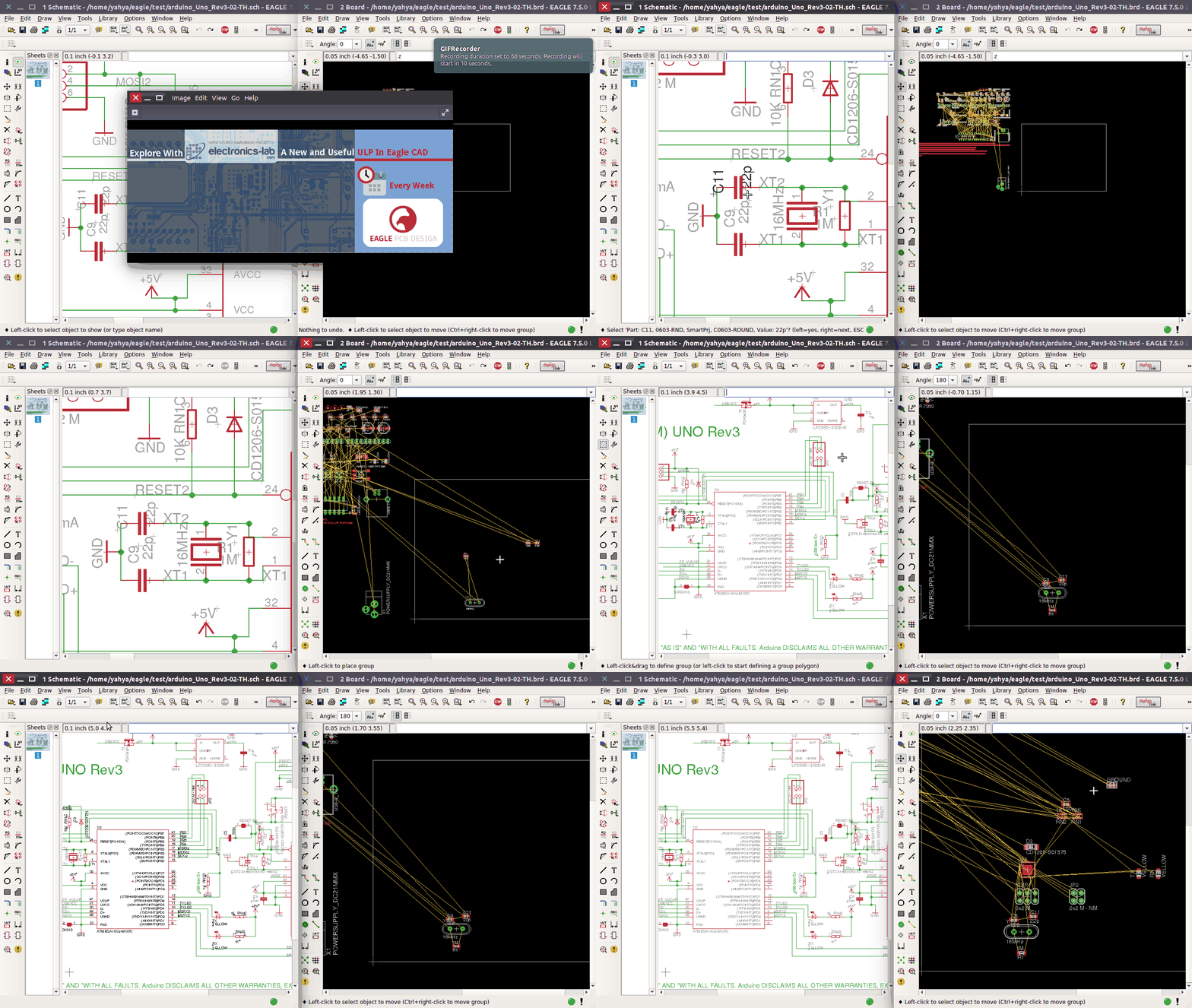
To use this ULP, you must select a group of components using GROUP tool then run “PickUp.ULP” from the schematic editor. Now when you will go to the layout editor, you will find the components you grouped them in the schematic editor movable as a group in the layout editor.
The below GIF demonstrates how this ULP works.
You can download the ULP from here: PickUp_ulp
See you in next post in this series with another useful ULP.











Looks good. May be you post ULP to import data from Kicad/Altium ?