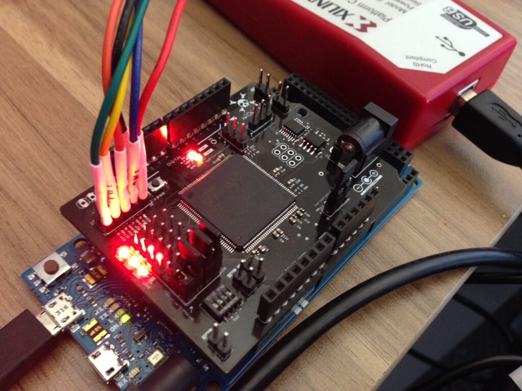
Inspired by an interest in spreading the concepts of FPGA, and because its ability to overcome most of other platforms limitations such as IO, memory, and peripherals, technolomaniac had worked on developing the first Arduino FPGA shield.
A Field-Programmable Gate Array (FPGA) is an integrated circuit designed to be configured by a customer or a designer after manufacturing. FPGAs contain an array of programmable logic blocks which include memory elements, and a hierarchy of reconfigurable interconnects that allow the blocks to be “wired together” to perform complex combinational functions, or merely simple logic gates like AND and XOR.
The FPGA shield includes additional I/O and memory resources, and it can be programmed either by SPI flash or via Arduino Due. Programming by the SPI flash from Arduino is done via the ICSP header which is carried on the shield board. The shield also include a second chip select (GPIO) to enable the ICSP to connect to the FPGA via SPI.
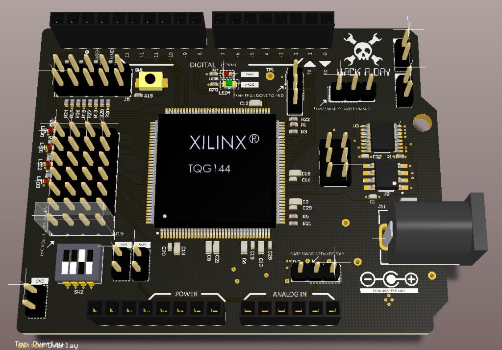
The PCB board contains these components:
- Xilinx Spartan 6 LX9 FPGA – device playground, a cost-optimized FPGA, offering high logic-to-pin ratios, small form-factor packaging, and a diverse number of supported I/O protocols.
- Spansion 16K flash – a 16K flash memory to hold FPGA configuration
- SPI Multiplexer – manages access to flash from multiple SPI sources
- Kyocera 20MHz CMOS Oscillator – FPGA clock source
- ISSI SRAM – 128Kx16 Asynchronous
The flash memory is large enough to be used by an FPGA processor, and also can hold multiple images of the FPGA configuration.
How-to video
The project is open source and all design files are available on Github.
For more details, build instructions, and project updates you can follow the project’s page on hackaday.





Arty Artix 7 has a similar layout with headers for Arduino shields for just 99$