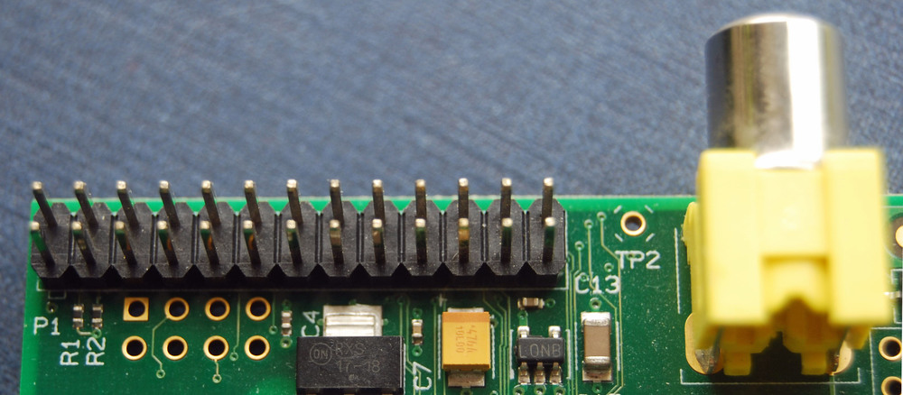
Working with microcontrollers means managing GPIO pins at some point. Many configurations have been developed for modern microcontrollers which can lead to some “fancy” terms that may confuse programmers. Its important to understand all of this to avoid confusion and errors while programming.
First, some terms need to be understood. GPIO pins have tri-state logic which means that contrary to popular beliefs GPIO pins can assume 3 states instead of 2. These values are: 0, 1 and high impedance or “Hi-Z”. There is also a state called floating which is when the state is indeterminate and floats between two states. As a result, the pull up and pull down were created, the pull up are resistors that connect a signal to VCC when the signal is floating, and pull downs do the same, but connect the signal to ground. Also, there is a “current sink” which is when the current is flowing into a pin, node, or signal. Conversely, there is a “current source” which is when the current is flowing out of a pin, node, or signal.
The modes of a GPIO pin can be classified into two categories: input, and output. Input mode means that the pin is used to read the state of the electrical signal, they are configured as high-impedance, pull up or pull down. Output modes are used to write a signal as high or low using push-pull or open drain. Push- pull is the default setting in most cases and it works by sourcing or sinking the current. On the other hand, Open- Drain only sinks current which basically makes it a switch with 2 states ground or disconnected. A useful application is for having multiple external devices drive a single, active low interrupt pin.
Regarding functionality, speed is a very important and desired characteristic for GPIO pins since it controls the rate at which it changes state. Speed configurations are referred as “slew rates”, “frequency”, and “high frequency mode”. Increasing speed leads to higher power consumption and a noisier device, so people tend to keep it low unless the project specifically requires more speed.
Another term is “High Drive” GPIO which are push-pull pins that provide more current that usual. These characteristics depend on the device and its recommended to check the datasheet, for example: if a typical GPIO can source/sink 8 mA a high drive device can source/sink 40 mA.
By reading this its easy to notice that the definitions are mostly things we are familiar with, and the only novelty are the terms used to describe them. Learning and understanding all the modes, functionalities etc. will make working with GPIOs easier and could avoid any issues. You can learn more about GPIO states on the source below.


