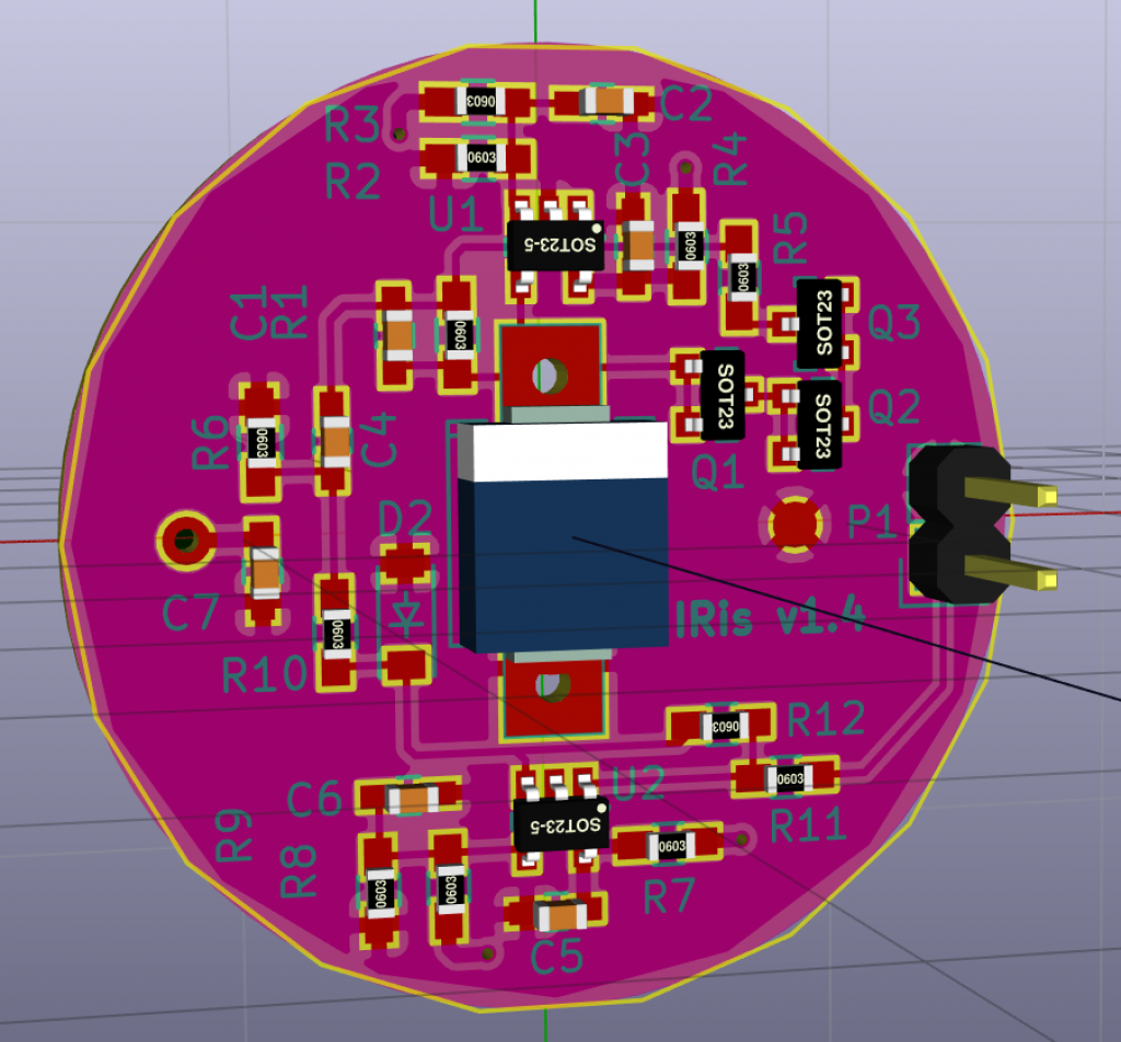
Craig Heffner/[devttys0] built this circuit for a friend’s Defcon talk, Blinded by the Light, the talk concerned about the emitted IR signals from the IR proximity detector in our devices like mobiles, and how we can identify the type of the device/OS using these signals.
Craig wanted to build a general purpose IR detector to capture and analysis the raw IR transmissions where IR receivers is designed to sense the modulated IR signals at 36-38 kHz. “But there is so much more to the world of IR than this” Craig said.
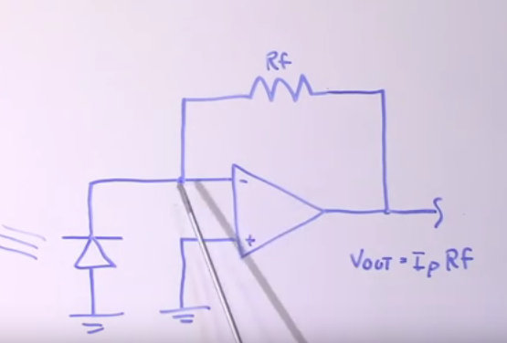
The first basic idea in the design is to use transimpedance amplifier which is basically a current-to-voltage converter.
When photons strike the photo diode, it will actually emit charge carriers, so the output of this sensor is a current. The output voltage (Vout= Ip*Rf) is linear in respect to the current.
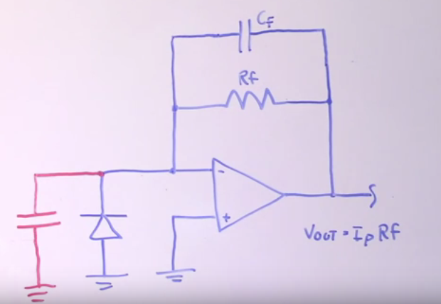
The major problem with this particular configuration is the unwanted high frequency oscillation, so a capacitor was added in parallel with the feedback resistor.
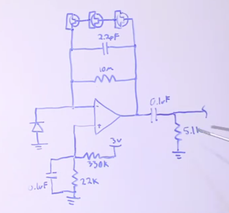
The next problem solved by Craig, is the saturation of the amplifier in high and low side by adding some bias resistors just to keep the reference voltage of the positive input of the op-amp at just under 200 millivolts.
To prevent saturation in high side he added three diodes, in fact three JFETs configured as diode, in the feedback path. The reason of using JFET configured as a diode is that it has less leakage current than normal silicon diodes, so when the voltage exceeds 3*0.7=2.1V then they short the feedback resistor, this point is important in our design because it has a current flow from photo diode.
The last thing to solve in first stage of the design is the problem of constant current from ambient light, which will generate a DC component in the output. So Craig added a high pass filter in the output.
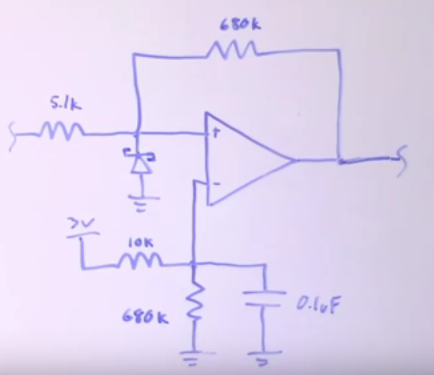
Now the circuit will still have some analog signals in output, noise and some negative spikes. So he cleaned things up by using a comparator with a Schottky diode in the non-inverting input to omit the negative pulses less than 0.2 Volt.
To see the full details of the design you can see the video below, and also you can reach the design files (SCH & PCB) over Github.
In addition, you can see the references pointed by Craig in his site analogzoo.


