AAEON’s new ACP-1075 and ACP-1078 offer easily integrated and managed compact solutions for industrial and retail needs.
Leading industrial PC provider AAEON has announced the release of two new All-in-One Panel PCs, the ACP-1075 and ACP-1078. Both new releases feature 7” WSVGA projected capacitive touch screens and compact, fanless chassis designs. Their distinct attributes indicate that AAEON has tailored them for specific markets.
The ACP-1078 is certainly the more versatile and rugged of AAEON’s new offerings, boasting an IP65-compliant aluminum front bezel, broad 12V to 24V power input tolerance, and both VESA and panel mounting options. As such, AAEON has earmarked the product for deployment in industrial settings, with data collection and monitoring in manufacturing and inventory management in logistics being key target uses.
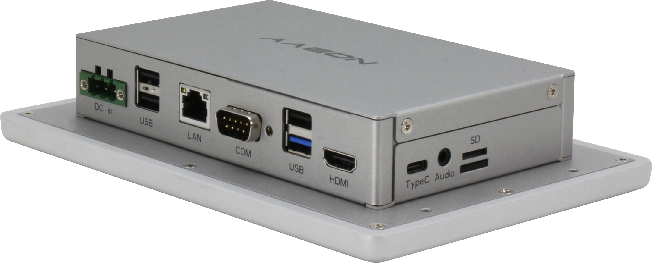
The ACP-1078 is powered by the Rockchip™RK3568 Quad-Core Arm® Cortex®-A55 processor and can support both Android™ 12 and Debian operating systems. Compared to previous generations of AAEON Panel PCs, the ACP-1078 stands out with up to 4GB of LPDDR4 system memory and a much denser range of interfaces. Among these are dual RJ-45 ports for Gigabit Ethernet, two COM ports (RS-232/422/485 x 1, RS-232 x 1), and two USB 3.2 Gen 1 ports, with one USB Type-C OTG for system recovery.
With AAEON marketing the solution for industrial environments, the inclusion of both HDMI display and audio output makes it well-suited for deployment in human-machine interface (HMI) applications. For expansion, the system offers a full-size mini-PCIe slot for either PCIe Gen 3 or SATA, along with a micro SD card to complement 16GB of onboard eMMC system storage.
AAEON’s second Panel PC offering, the ACP-1075, is aimed at customers who need a cost-effective, compact open-frame solution that can be easily installed in applications like smart kiosks. It comes with either the Intel® Pentium® Processor N4200 or an Intel® Celeron® Processor N3350, and runs on a 64-bit Windows OS. The ACP-1075 is designed to be efficient in deployment and operation.
Despite its compact 7.18” x 4.73” x 2.09” size, the ACP-1075 offers strong storage and expansion options. It comes with 64GB of onboard eMMC, along with both M.2 2280 B-Key and M.2 2230 E-Key slots, providing support for SSDs and Wi-Fi modules for multimedia content and wireless connectivity. These features are useful for remote updates and monitoring.
Onboard interfaces include three USB ports (two USB 3.2 Gen 1 and one USB 2.0), one RJ-45 port for Gigabit Ethernet, and two DB-9 ports offering RS-232 for cost-effective, reliable, and straightforward serial communication. Crucially, there is also an HDMI display port to complement the system’s multi-touch touchscreen.
For detailed specifications and more information about the ACP-1075 and ACP-1078, please visit https://www.aaeon.com/en/ or contact your AAEON representative via AAEON’s dedicated contact form.
This simple circuit illuminates an LED or bulb using a ripple counter in a specific order at a predefined interval.
Electronics enthusiasts and students often like building different circuits for their home or school projects, particularly those that flash a few lights. One incredibly flexible integrated circuit (IC) that may be used to create a straightforward LED flasher circuit is known as a binary ripple counter. Several circuits and kits in the market can flash any number of LEDs or lights intermittently, randomly, or consecutively.
As we have discussed in the Counters’ lesson, ripple counters are toggle flip-flops that we can utilize in our basic LED flasher design to act as frequency dividers, dividing the reference clock input by a particular period to produce a new, lower-frequency signal.
Since not every flip-flop in these counters’ “toggles” in unison when an external clock pulse is applied, these counters are termed asynchronous. Typically, the toggling takes place on the clock pulse’s negative edge.
The fundamental feature of all counters is the toggle, also known as a “T-type” flip-flop. Asynchronous counters are also known as “Ripple counters,” because the input clock pulse appears to “Ripple” through the counter when the clock input for one stage is generated from the output of the preceding stage. When each step changes sequentially, the outcome is a ripple effect, which may be effectively used to create a basic LED Flasher circuit.
Ripple counters comprise a series of divide-by-2 T-type flip-flops cascaded together to produce a single divide-by-N frequency divider, where N equals the counter’s bit count. The 74LS93 4-bit (÷16), CMOS 4024 7-bit (÷128), CMOS 4040 12-bit (÷4096), and the bigger CMOS 4060 14-bit (÷16,384) counter are examples of commonly available binary ripple counter integrated circuits.
The “Nth” step of the counter would then be defined as their output count (Qn). Thus, for instance, output Q6 is 26 = 64 (1/64 of the clock frequency), Q12 is 212 = 4096 (1/4096 of the clock frequency), and so on.
The CMOS CD4040B 12-bit Binary Counter is a very versatile integrated circuit that can be used to create a basic LED flasher for use in a variety of different lighting displays. As we’ve seen, there are many binary counters available that can flash any number of lights periodically, randomly, or sequentially.
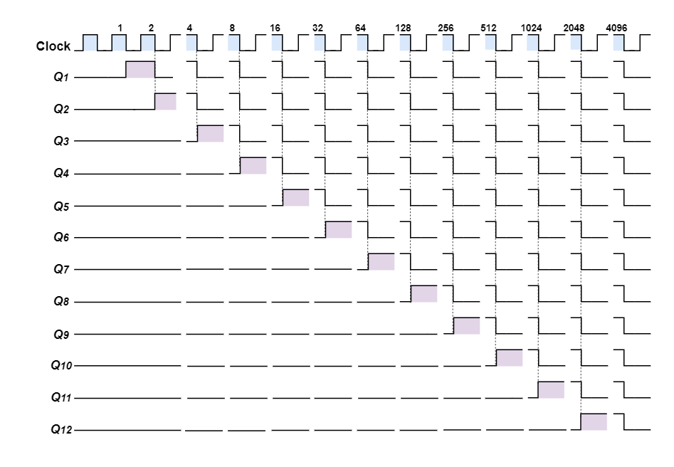
The CD4040B is a 12-bit binary ripple counter that switches quickly and has twelve completely decoded outputs, or a total of twelve different LED sequences. As each clock pulse’s negative edge approaches, these twelve outputs successively switch, creating the binary output sequence seen in the timing diagram.
For a lights project, the 4040 is perfect as a simple LED flasher or lighting display since its outputs alternate between a logic “1” or “HIGH” and a logic “0” or “LOW” on each count, allowing it to create a moving sequence, chaser, or random effect.
Given that the 4040 is a 12-bit ripple counter, the timing diagram that follows illustrates how each of the twelve outputs will alternate between HIGH and LOW in a binary sequence ranging from 0 to 4096 (212).
4040 Ripple Counter Timing Diagram
Fig-1: 4040 Ripple Counter Timing Diagram
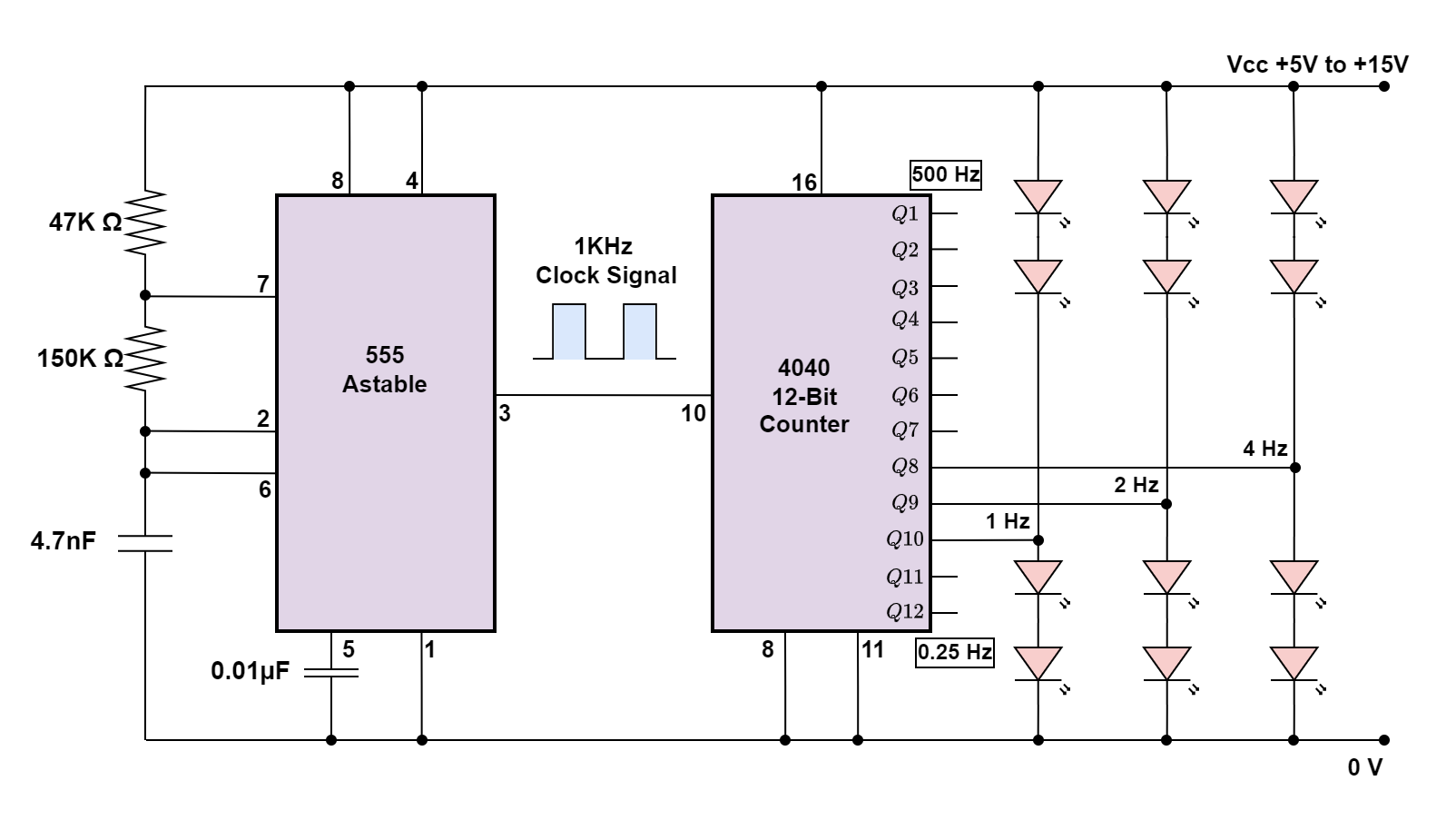
To include the 4040B ripple counter into our basic LED Flasher circuit, we must first generate a timing signal. A timing or clock signal can be produced in many ways—the possibilities are virtually limitless. However, utilizing a specialized timing integrated circuit (IC) like the NE555 Astable Timer is a very easy and efficient approach to producing a square wave timing signal with the fewest possible components.
The selected input clock frequency determines the timing period T, where T = 1/ƒ. Therefore, our input clock frequency on pin 10 of the 4040 counter would need to be approximately 1kHz, (0.25 x 4096), as shown, if we decide to use the 4040 12-bit (÷4096) counter as part of our simple LED flasher circuit and we want our longest timing period on the 12th-bit to be 4 seconds (2 seconds ON and 2 seconds OFF), or 0.25Hz.
Simple LED Flasher Circuit
Fig-2: LED Flasher Circuit
Our simple LED flasher circuit will work best if the LEDs are connected with different outputs since they will flash one at a time, but at separate rates from one another (each output is half the frequency of the preceding one), and they won’t all be “ON” or all “OFF” at the same time.
Depending on which ripple output you connect the LEDs to and how you physically arrange them, you can create any kind of LED flashing light display or a twinkling star effect by using divide-by-2 frequency dividers/counters and multiple LEDs connected to their outputs.
Ripple Counter Output
The outputs of the counters, Q1 through Q12, may either “Source” or “Sink” a load current up to a maximum of around 15mA, which is sufficient for operating the LEDs directly.
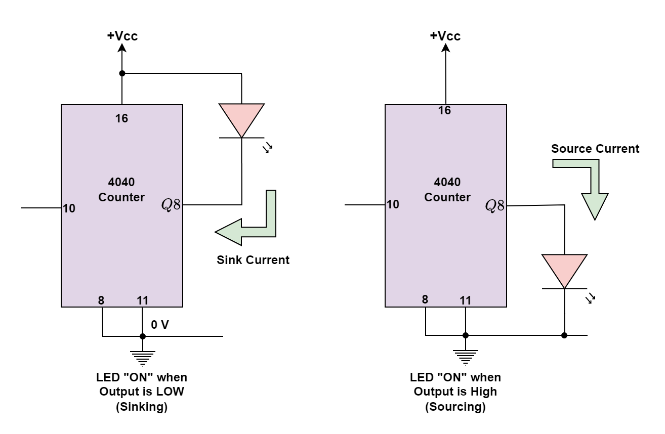
Because the 4040 counters can “source” (supply) as well as “sink” (absorb) current, LEDs can be connected between the counter’s output terminal and ground to source load current, or between the counter’s output terminal and supply to sink load current. The illustration for the Sourcing and Sinking is shown in the figure below.
Sinking and Sourcing the Outputs
Fig-3: Sinking and Sourcing
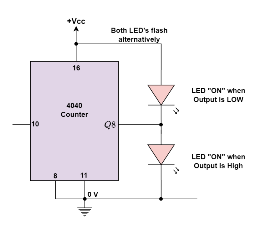
The LED in the first circuit above is linked to the output, in this instance Q8, and the positive supply (+Vcc). This indicates that when the output is “LOW,” the current will “sink” (absorb) or flow into the 4040 counters’ output line, turning on the LED.
The LED is linked between the output, Q8, and ground (0 volts), as the second circuit above demonstrates. This indicates that when the output is “HIGH,” the LED will be “ON” and the current will “Source” (supply) or flow out of the 4040 counters output port.
We can utilize more LEDs in our simple LED flasher circuit because the ripple counter can source and sink its output load current, allowing both LEDs to be connected to a single output terminal. Only one LED will, however, be turned “ON” at any one moment based on whether the output state is “HIGH” or “LOW.”
Fig-4: Dual LED with Sink and Source
An example of this is shown in the above-shown circuit. Depending on the output, the two LEDs will alternately be turned “ON” and “OFF,” producing an alternating flashing movement. If necessary, series resistors can be added to lower the LED current to less than 15mA.
As we mentioned earlier, the output pins may sink or source the load current up to a maximum of 15 mA, which is more than sufficient to drive or switch LEDs, tiny lights, and other similar devices. However, what if we wished to use this simple LED flasher in place of switching or controlling higher-power equipment like motors, electromagnets, or relays? Then, to supply an adequate current to drive the load, transistors would be required.
Ripple Counter Transistor Driver
Fig-5: Ripple Counter Transistor Driver
If the load current is high, the transistor in the first two cases can be swapped out for a Power MOSFET or a Darlington transistor. It is best to connect a “freewheeling diode” straight across the load terminals of an inductive load, such as a motor, relay, or electromagnet, to absorb any back EMF voltages produced by the inductive device as it changes state.
More LEDs may be added to the output, but they typically need 15 to 20mA at 1.2V to properly glow, when the circuit is connected to a battery or power source. The 4040 IC has the benefit of self-limiting its maximum input/output current, which allows LEDs to be connected directly without the use of current-limiting resistors.
Conclusion
A simple LED Flasher circuit can be constructed using a binary ripple counter. A binary ripple counter, an integrated circuit (IC), is ideal for this purpose due to its ability to divide frequencies and create sequential outputs.
Several binary ripple counter ICs are available, such as the 74LS93, CMOS 4024, CMOS 4040, and CMOS 4060, each offering different division capabilities. The CD4040B, a 12-bit binary ripple counter, is highlighted for its versatility in creating LED flashers. It can generate twelve distinct LED sequences, switching outputs with each negative edge of the clock pulse.
To generate the necessary clock signal for the CD4040B, an NE555 Astable Timer IC is suggested. The timer can produce a square wave timing signal with minimal components. By adjusting the input clock frequency, different flashing rates can be achieved. For example, a 1kHz clock frequency will create a 4-second on/off cycle on the 12th-bit output.
Transistors or MOSFETs are used to switch higher-power loads, such as motors or relays if needed. Freewheeling diodes are recommended across inductive loads to absorb back-EMF voltages. Additional LEDs can be connected to the outputs, and the 4040 IC’s current-limiting feature allows direct connection without resistors.
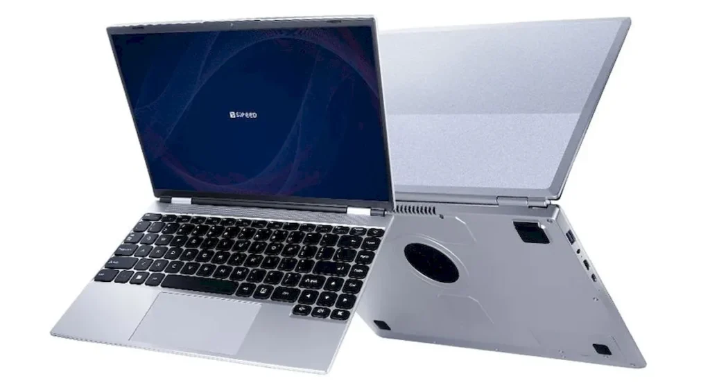
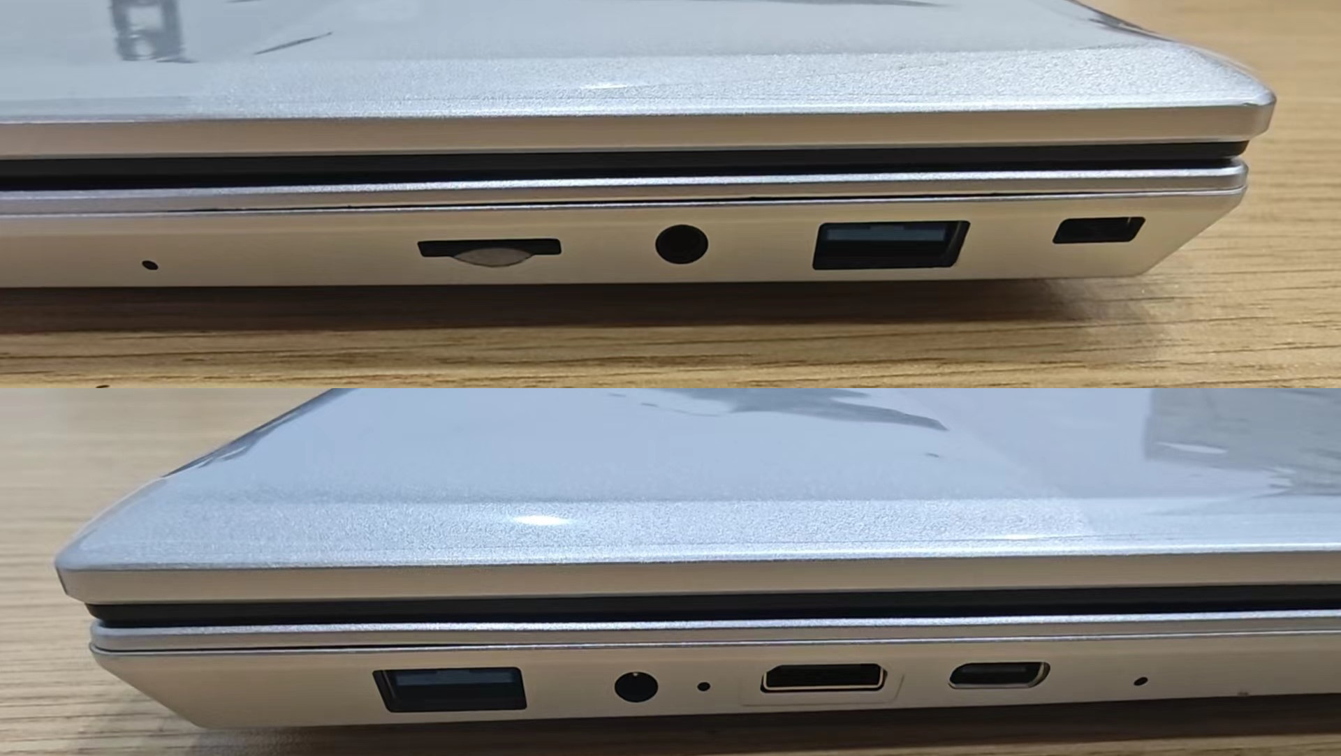
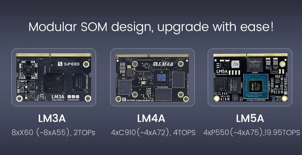
Sipeed Lichee Book 4A is a RISC-V lightweight laptop featuring a 14-inch 1920×1200 display, RISC-V TH1520 SOM (8+32/16+128 options), and various connectivity options including USB-A, USB-C, SSD slot, and more. It is designed for RISC-V developers to explore real-life applications of RISC-V technology.
The TH1520 is born out of the Wujian 600 platform unveiled by Alibaba in August 2022 and is capable of running desktop-level applications such as Firefox browser and LibreOffice office suite on OpenAnolis open-source Linux-based operating system launched by Alibaba in 2020.
In our previous post, we also wrote about the Lichee Console 4A, a compact laptop powered by a Lichee Pi 4A RISC-V processor. It has 16GB of RAM, multiple storage options, and built-in Wi-Fi. Feel free to check this out if you are looking for similar products.
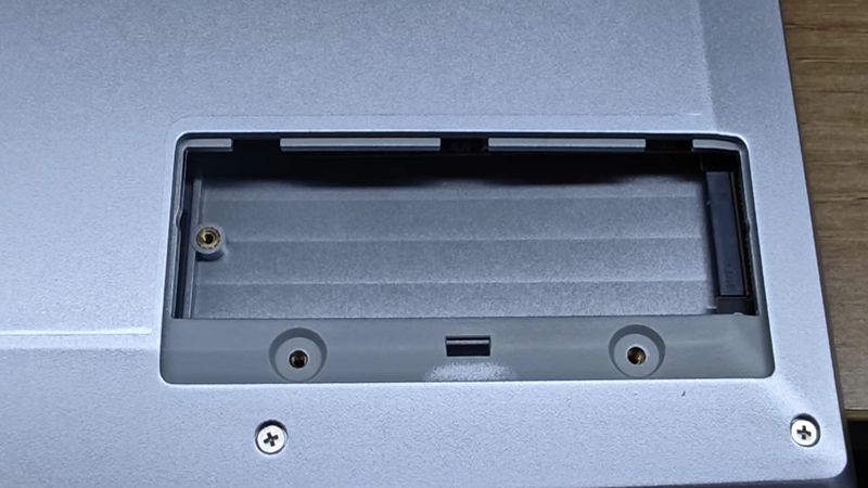
The Book supports M.2 2280 SATA SSDs, which can be installed by removing the SSD cover on the back. If you do not plan to use an SSD, you can manually turn off the USB-to-SSD chip to reduce power consumption (about 0.6 watts) and extend battery life.
Sipeed Lichee Book 4A is available on AliExpress for just $188.80 without the CPU module for people who already own a Lichee LM4A system-on-module. You can buy a complete laptop with an 8GB/32GB variant at $298.40 and a 16GB/128GB variant at $348.80 on the same link. Shipping charges apply according to the delivery time of this product.
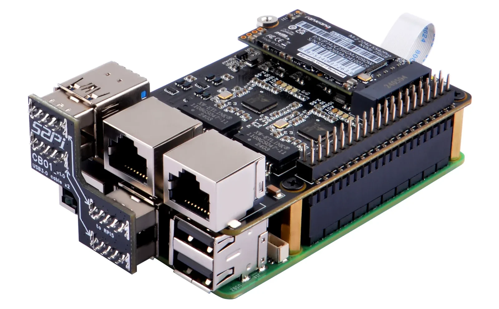
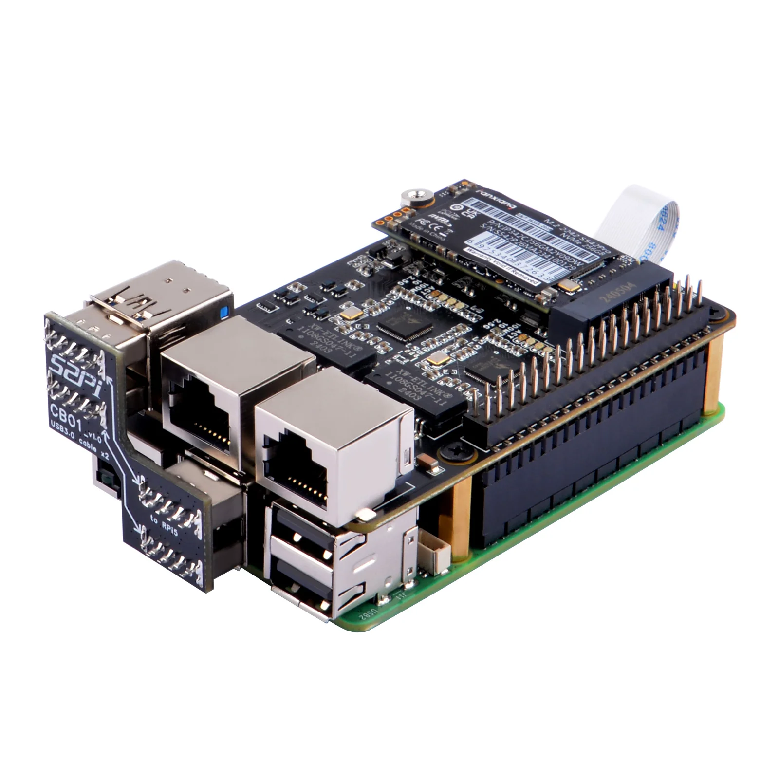
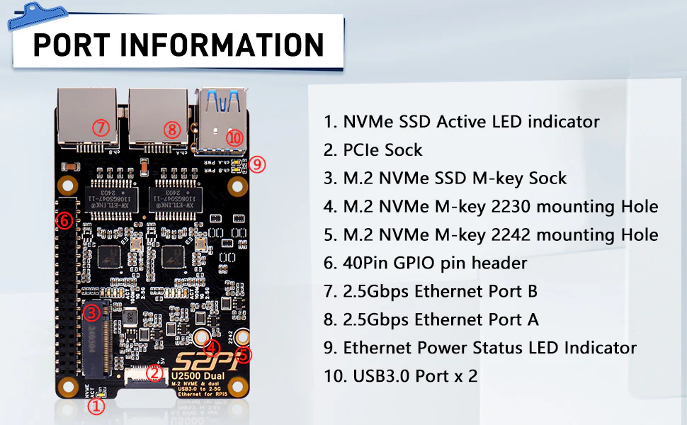
52Pi W01 U2500 HAT is an expansion module designed to add 2.5GbE Ethernet and M.2 NVMe SSD to Raspberry Pi 5. This configuration makes it easy for users to build NAS, databases, media servers, and other applications with the Pi5.
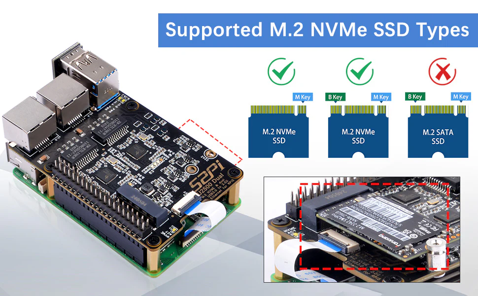
The U2500 supports M.2 M-key NVMe SSDs (2230, 2242, 2260, and 2280) with 2.5 GbEEthernet with a Realtek RTL8156BG chipset. For fast access and support the M.2 SSD is connected directly to the Raspberry Pi’s PCIe port that supports Gen2 & Gen3 standards. But one of two 2.5GbE ports gets connected to a USB port of the Pi using a special adapter that ships with the product.
Previously we have written about products developed by 52Pi including the 52Pi NVMe M.2 HATs and other PCIe HATs for the Pi5 like the Raspberry Pi AI kit, the PI-5 connector adapter, and much more, feel free to check those out if you are interested in the topic.
The HAT converts two USB 3.0 ports into two Gigabit Ethernet interfaces, ideal for web servers and IoT projects. It mounts securely onto the Raspberry Pi 5 with four holes, leaving the 40-pin GPIO header accessible.
Form Factor: Raspberry Pi HAT
Compatibility: Raspberry Pi 5 (exclusive!)
Storage:
M.2 NVMe (M-key)
2230/2242 SSD sizes supported
Networking:
Dual 2.5 Gigabit Ethernet ports
USB 3.0 to Ethernet conversion
Interface: PCIe x1 (for NVMe)
Power: Draws power from Pi’s USB ports (no external needed)
Misc: LED indicator for M.2 disk activity.
Dimensions: 85 x 56 x 15.15mm
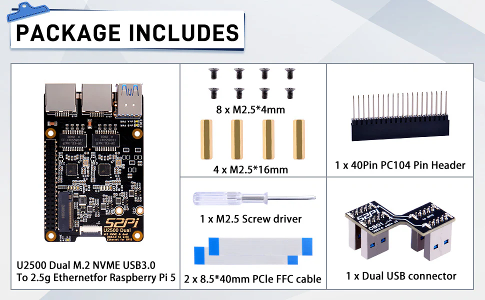
The package comes complete with everything needed to mount the HAT onto your Raspberry Pi 5. Included are the W01 U2500 HAT, screws, PCIe cables, pin header, copper pillars, an SSD securing pillar, and a screwdriver for easy installation. More information about this HAT can be found on the Wiki Page.
This U2500 HAT is available for $49.99 on the 52Pi online store. However, note that the Wiki page for this product is not available as of the publication date.
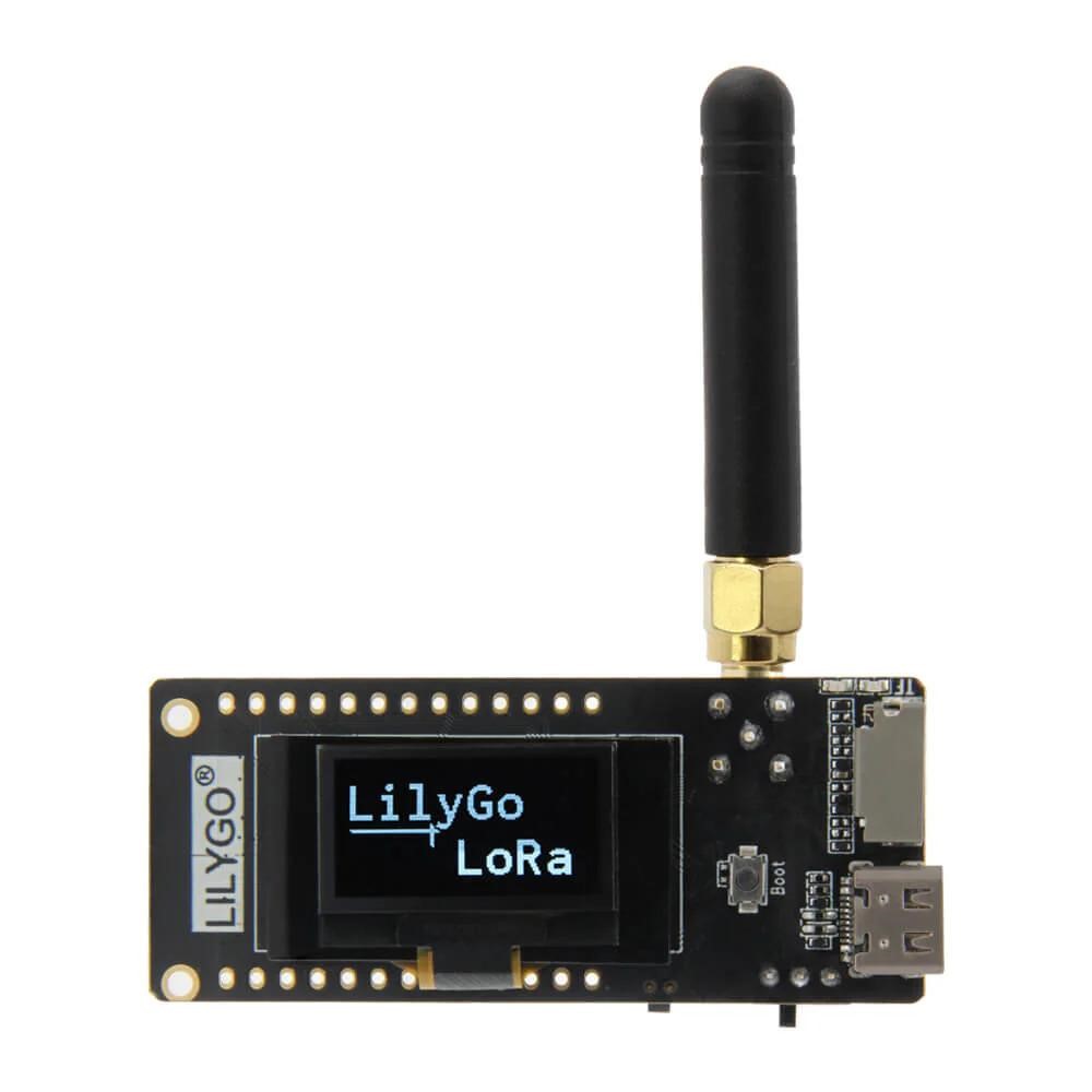
The IoT industry is constantly looking for improvements in boards that fixate on communication interfaces and low-power performance. We recently came across LILYGO’s T3-S3 ESP32-S3 board which can be lauded for its long-distance communication capabilities and energy efficiency.
Key Specifications and Features
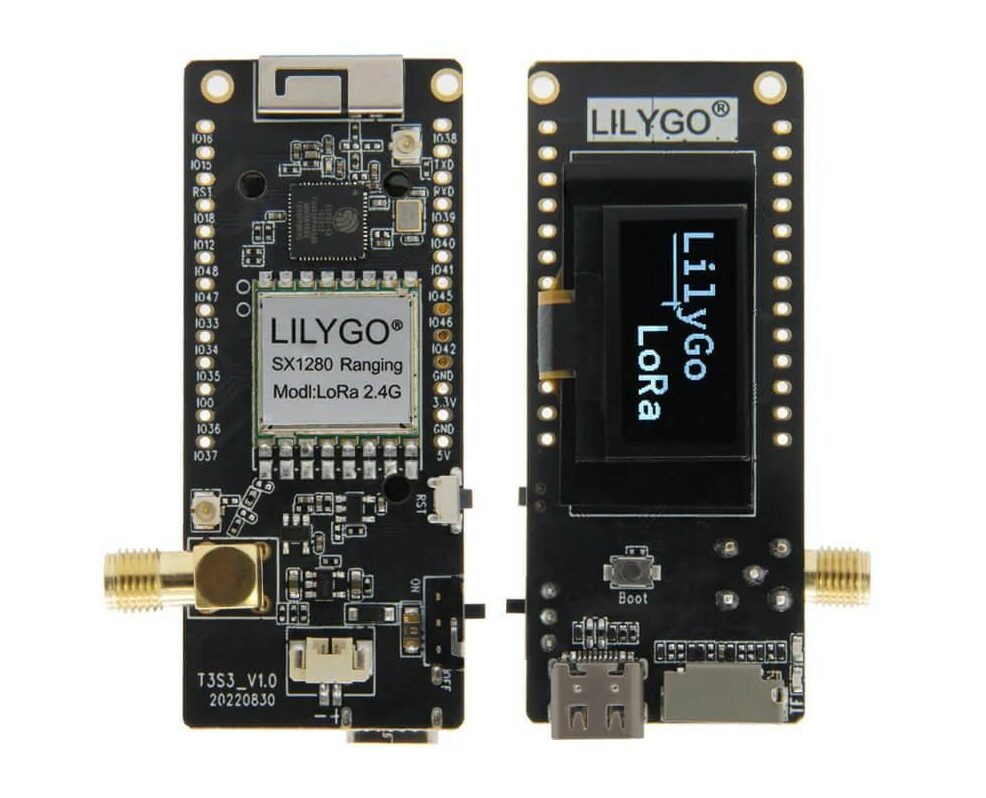
The T3-S3 ESP32-S3 board uses the SX1280 LoRa Transceiver for communication which operates at 2.4 GHz frequency. Note that a power amplifier can be used with the SX1280. Here, a Power Amplifier is used for boosting the signal strength and increasing the signal quality which could be convenient with IoT networks spanning geographically. Additionally, with the PA, users have the liberty to either prioritize “maximizing range” or “optimizing power consumption” as needed. SX1280 also has a high-efficiency PA giving +12 dbm, and a low RX current of 9.9 mA. The recommended chip output is 2-5 dbm, ensuring the module output to 20 dbm. The optimal setting for damage prevention is 3 dbm, any setting higher than 5 dbm can damage the FEM resulting in weak or unclear signals.
SX1280 is one of the first transceiver ICs to have time-of-flight functionality. It can operate in “Mesh Network”, meaning if one of the devices in the mesh goes offline, data can travel through another path, or a device can act as a relay between two devices. These factors make T3-S3 useful for remote applications or for communication in places without cellular coverage. This makes the T3-S3 ESP32-S3 board more reliable.
The micro-controller unit of T3-S3 is ESP32S3FH4R2, having memory specifications as 4MB FLASH, and 2MB PSRAM with QSPI, this gives the board the ability to make external memory as fast as internal memory. The flash memory chip works at a maximum speed of 80MHz and does not support auto-suspend. Although a speed of 120MHz or auto-suspend functionality can be achieved, to do so please contact espressif.
Interfaces
Coming to interfaces, the T3-S3 ESP32-S3 board comes with SMA and two IPEX connectors. SMA connectors find themselves in RF applications. One of the IPEX connectors is near the SMA connector and the other is near the Wi-Fi antenna. As they are compact they are used in applications with limited space. Also, these connectors can be used for both RF and Wi-Fi communication giving users more options and versatility.
The T3-S3 ESP32-S3 board can be connected to external devices via various ports and pins such as,
21 multi-function GPIO pins.
USB type-C connector.
TF card slot.
Wifi and Bluetooth 5.0
The peripheral interfaces include SPI, I2C, and ADC.
A Reset + Boot button.
Included Accessories with T3-S3 Board :
Some miscellaneous features included in the board:
1 LoRa antenna.
The OLED display of 0.96 inches has a resolution of 128×64 with I2C driver.
1 JST 2.0mm 2P for connecting a battery.
2 2.54mm Male PIN (1*13P).
This board is compatible with Arduino IDE, Micropython, and ESP-IDF for programming. This allows users from all software backgrounds to easily work on this board.
LILYGO’s T3-S3 ESP32-S3 LoRa 0.96 inch Development Board fit for IoT applications is available on the Lilygo website. Meanwhile, the sample codes are available on their Github.
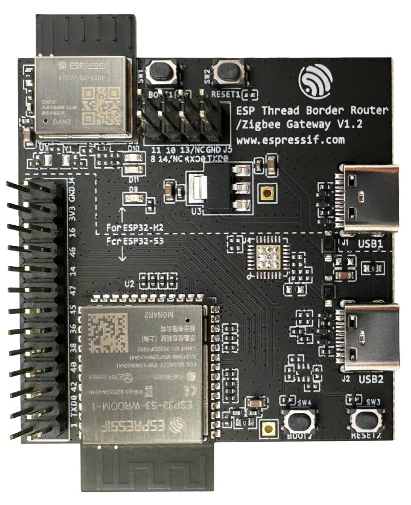
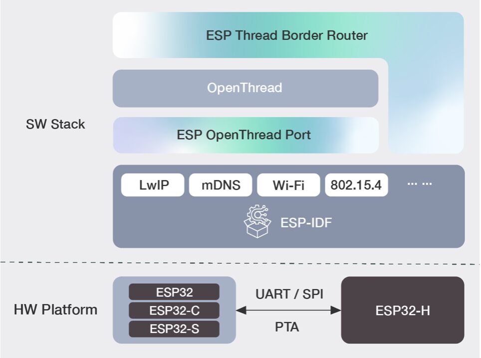
Espressif Thread Border Router is a SP32-H2 (802.15.4) and ESP32-S3 (WiFi + BLE) powered development board that has acquired Thread Interoperability Certificate V1.3, which makes it a Thread-Certified Component that supports Matter application scenarios.
The ESP Thread Border Router supports the latest Thread 1.3 standard, including features like IPv6 connectivity, service discovery, multicast forwarding, and NAT64. Additionally, it offers product-ready functionalities such as a web configuration interface, automatic updates, and optimized radio performance.
Espressif Thread Border Router Specifications
ESP32-S3-WROOM-1
SoC: ESP32-S3 dual-core 240 MHz with 2.4 GHz Wi-Fi 4 and Bluetooth 5.0 LE
Memory: 2MB PSRAM
Storage: 4MB SPI flash
Dimensions: 25.5 x 18 x 3.1 mm
ESP32-H2-MINI-1 (D4N2)
MCU: ESP32-H2 96 MHz RISC-V with Bluetooth 5.2 LE/Mesh and 802.15.4 radios
Storage: 2MB flash
Dimensions: 13.2 x 16.6 x 2.4 mm
Interfaces (ESP32-S3 <-> ESP32-H2):
UART, SPI
RESET, BOOT
3-wire PTA for RF coexistence
Connectivity
USB: 2x Type-C (one for each module)
Expansion
ESP32-S3: 26-pin GPIO header
ESP32-H2: 8-pin GPIO header
Additional Features
Reset and Boot buttons for each module
3 user LEDs on ESP32-H2
Espressif offers an optional ethernet board to add Ethernet, HMI, and voice control to their development board. This versatile board is primarily for Thread Border Router development but can also be used for Zigbee Gateways.
The ESP Thread Border Router SDK, sample code, and documentation are available on Espressif’s website and GitHub. Zigbee hardware support exists, but the corresponding SDK has not been released yet.
Cost-effective from lot size one, readily available, highly variable
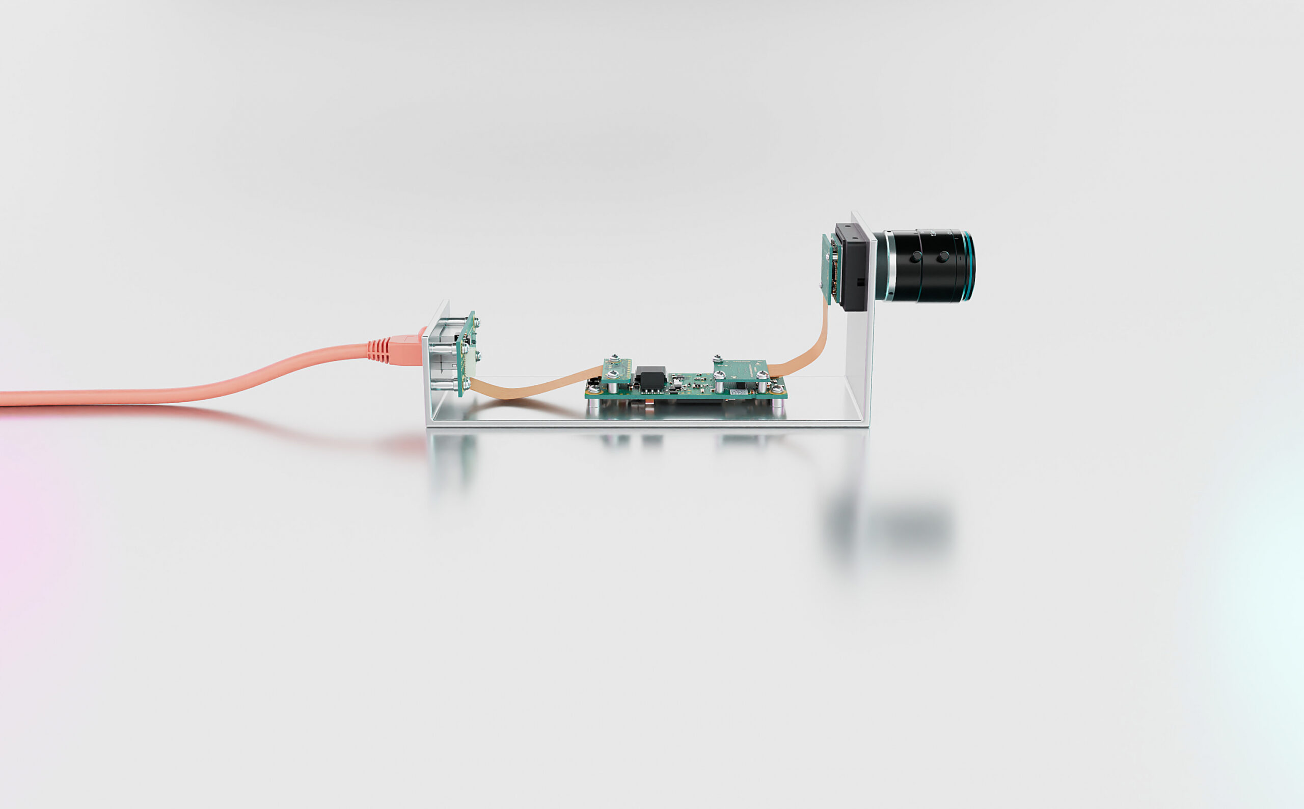
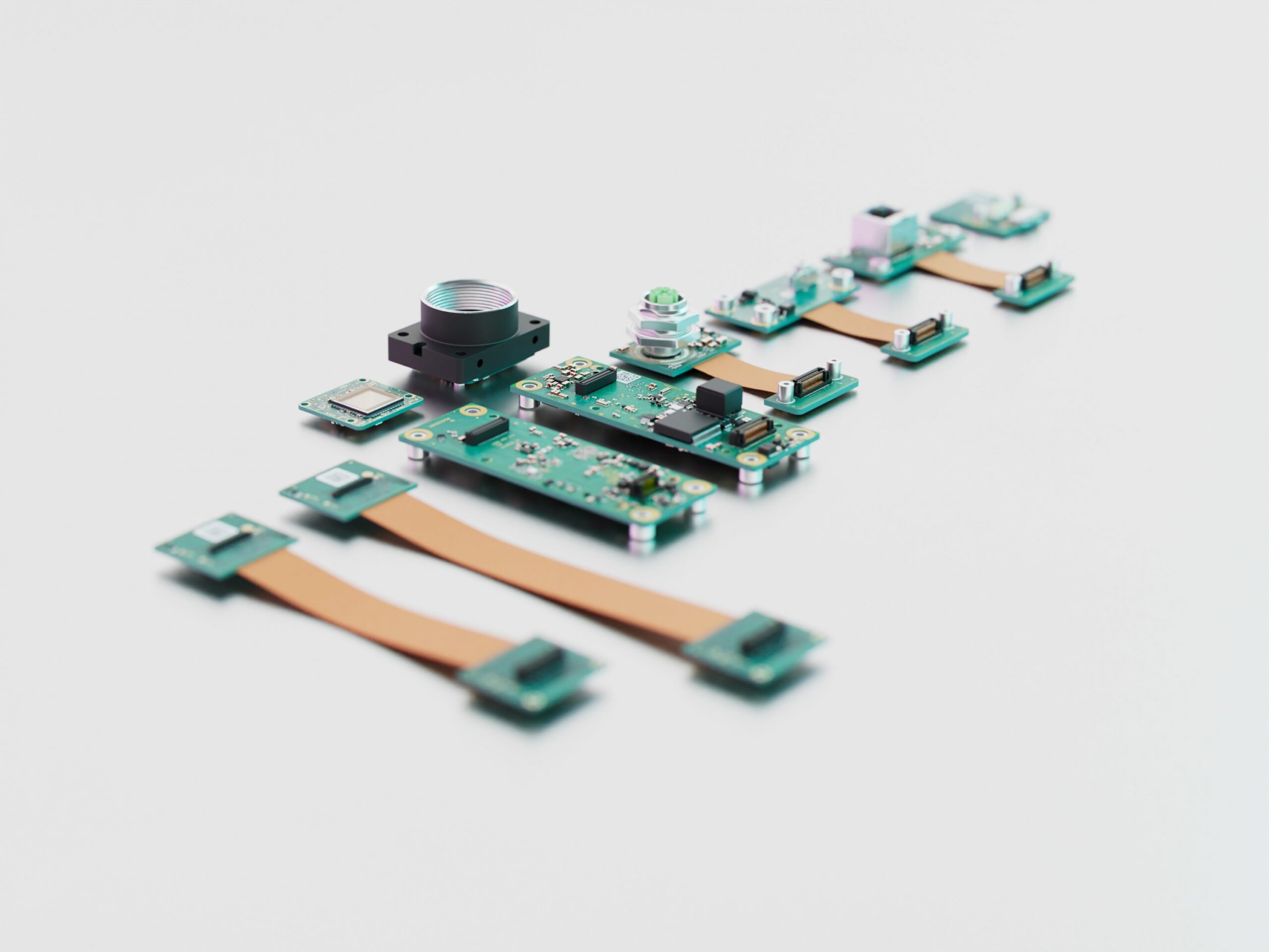
As versatile as the IDS industrial camera families are, sometimes customer requirements are so particular that a customized development would be desirable. However, this often only makes sense for larger quantities. For this reason, the company has developed the uEye ACP series: its modular design principle allows for a vast range of camera variants. The online configurator helps to put together unusual models that are available from stock. True to the philosophy: be uncompromisingly happy instead of making compromises.
IDS Imaging Development Systems has developed all essential camera components for the uEye ACP series – such as sensor boards, connectors and lens holders – as standard modules that can be freely combined. The range includes USB3 and GigE Vision interfaces, connector boards with various connector options, flex cables and a wide range of image sensors from 0.5 to 20 MP.
uEye ACP allows for a wide range of combinations
Customized board-level cameras are available off the shelf in quantities as low as one, without the usual development cycles of individual projects. Furthermore, customers have the option of receiving the camera fully assembled or as individual components. As is customary for IDS, careful testing before shipment and quality “Made in Germany” are a matter of course in both cases.
In addition to the uEye ACP product line, the industrial camera manufacturer also takes on customized development projects. On request, an experienced team carries out everything that is technically possible, from individual design to adaptations of the housing, board electronics and connector configuration, as well as software adaptations.
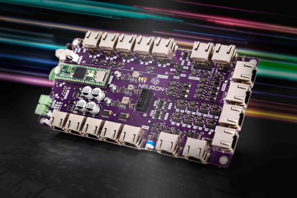
Neuron-1 is a universal 5-axis CNC motion controller used to control CNC machines, such as milling machines, routers, and lathes, and the most unique thing about this board is that it uses RJ45 connectors to make a plug-and-play system. The board is based on Teensy 4.1 and includes a variety of features that make it easy to use and install, including the RJ45 connectors, a plug-and-play system, and configurable inputs and outputs. It is also compatible with a variety of firmware and software.
24-5V outputs for spindle, coolant, dust extraction
3x 24-5V auxiliary outputs (M-code controlled)
0-10V / 5V PWM for spindle VFD/laser
Connectivity:
USB
Ethernet
SD Card
Auxiliary USB
I2C
Additional:
5/24V input/output configurable
POE-style power over I/O
Reverse polarity/fuse protection
Compatible with IoSender, (future) CortexInterface software
Form Factor: Compact module with RJ45 connectors
In terms of software and tools, the board supports GrblHAL firmware and IoSender software, and on the products page, the company mentions that the support for CortexInterface software is an upcoming feature of there.
Italian startup Cortex Automation designed the board so that it’s plug-and-play and includes everything you’ll need to build a CNC device with ease. Other than that not much information about the board is available at the time of writing. But upon searching for a bit I found the GitHub repo for the Neuron-1 you can check that out if you want to find some more information about the product.
The company is not selling the board right now and does not mention when the board will be available for sale more information about that can be found on the Neuron-1 products page.
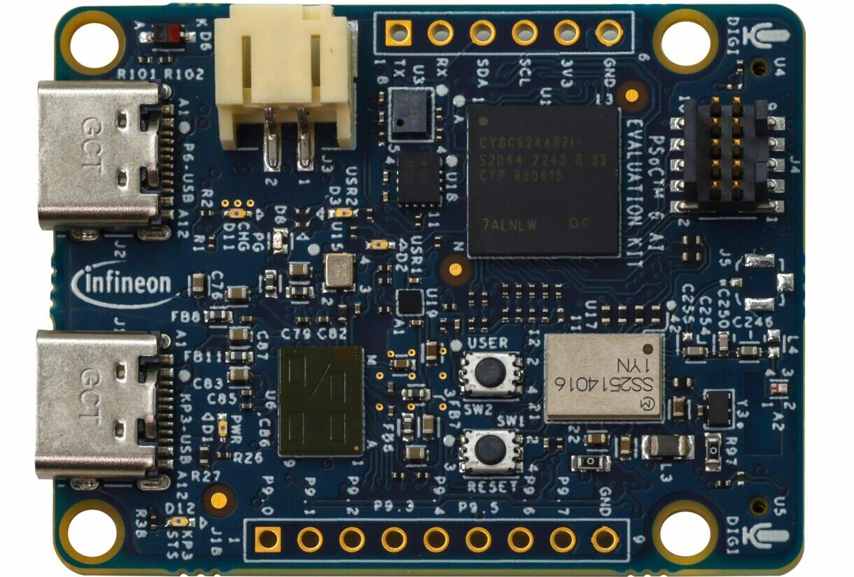
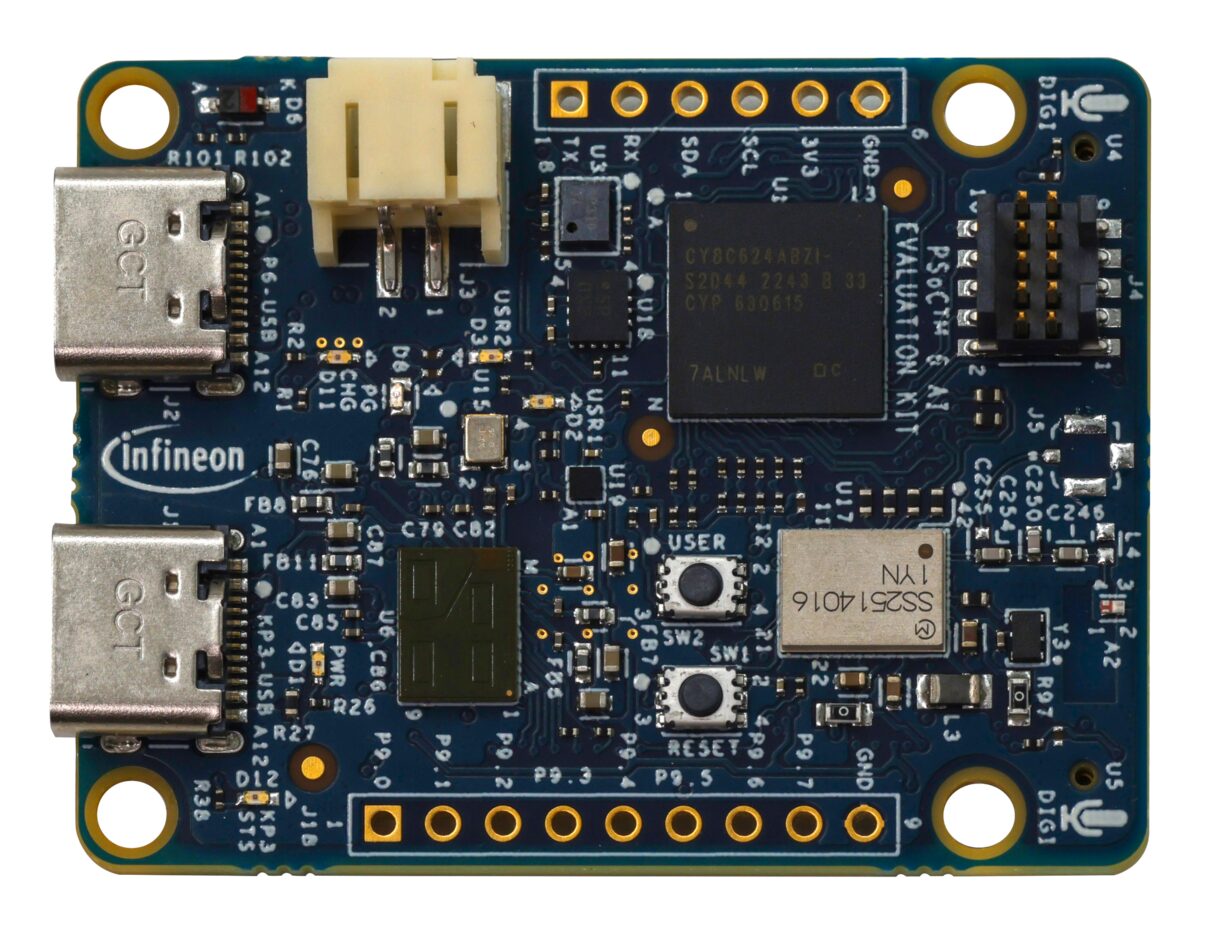
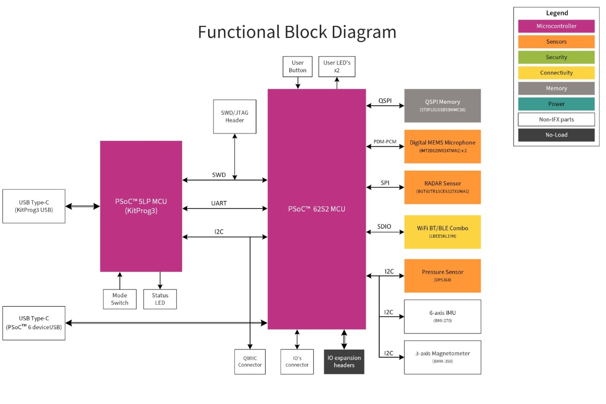
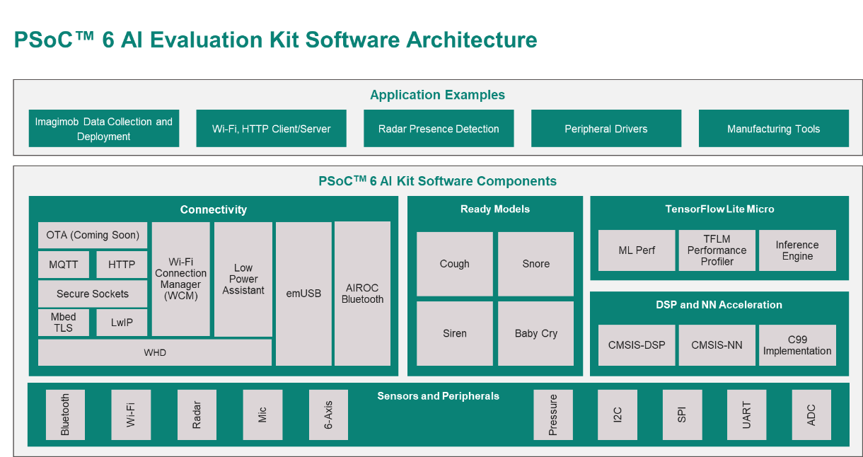
Infineon CY8CKIT-062S2-AI Evaluation Kit is a Hardware platform focused on Machine Learning (ML). Built around the PSoC 6 family of MCUs this dev board includes sensors like radar, microphone, magnetometer, IMU, air pressure sensor, and much more. The board features Wi-Fi and Bluetooth for connectivity and includes an expansion header that can be used to connect other modules and sensors. These features make this board useful for applications like smart home automation, industrial monitoring, wearables, etc.
Previously we have written about similar AI and Machine learning-powered dev boards like the TIDEP-01004, the Avnet RASynBoard, the AISonic IA8201 feel free to check those boards out if you are interested in the topic.
Infineon CY8CKIT-062S2-AI Dev Board Specifications
Secure onboarding, boot, key storage, and firmware updates
Trusted firmware-M security services
Debugging and Programming
KitProg3 onboard debugger and programmer
Dimensions: Not Mentioned
The evaluation kit includes pre-built machine-learning models for easier application development. It’s compatible with Infineon’s ModusToolbox software, a versatile embedded development tool used in the PSoC 64 IoT Security Workshop Development Kit. ModusToolbox supports machine learning, connectivity, and security and is compatible with Windows, Linux, and macOS. The board also supports the Imagimob Studio platform, simplifying the creation and deployment of machine-learning models on small devices like the PSoC 6 MCU.
The board also supports TensorFlow Lite Micro and neural network acceleration via CMSIS-DSP and CMSIS-NN. Combined with robust hardware and connectivity options such as MQTT, HTTP, and AbIROC Bluetooth, it facilitates rapid prototyping and the development of AI applications.
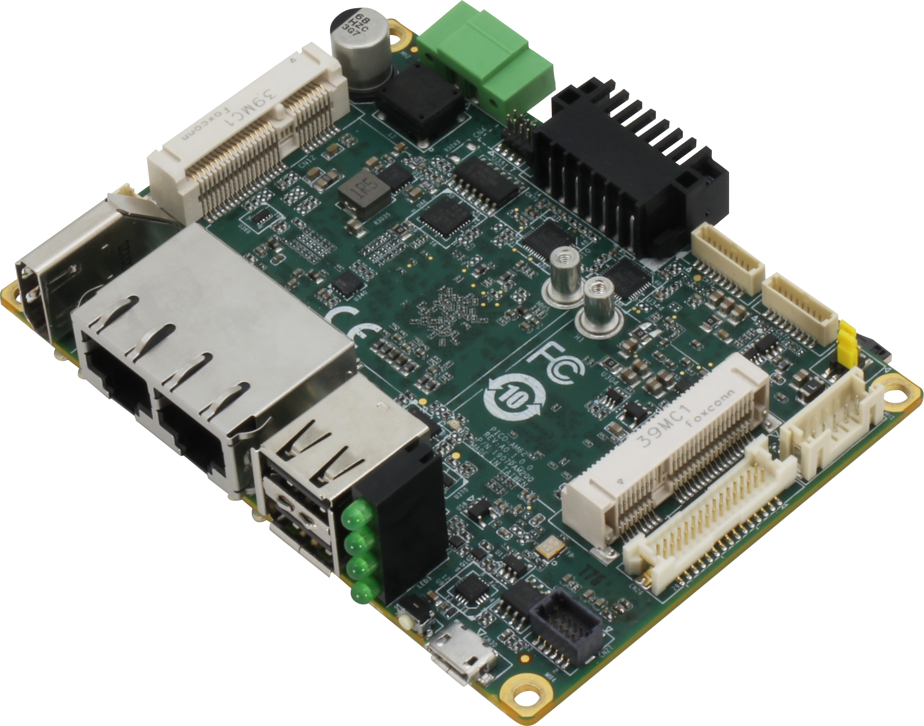
Compact, environmentally resilient, and incorporating Texas Instruments AM62x Sitara Processors, the PICO-AM62 & SRG-AM62 show AAEON make big moves in cost-efficient RISC-based computing.
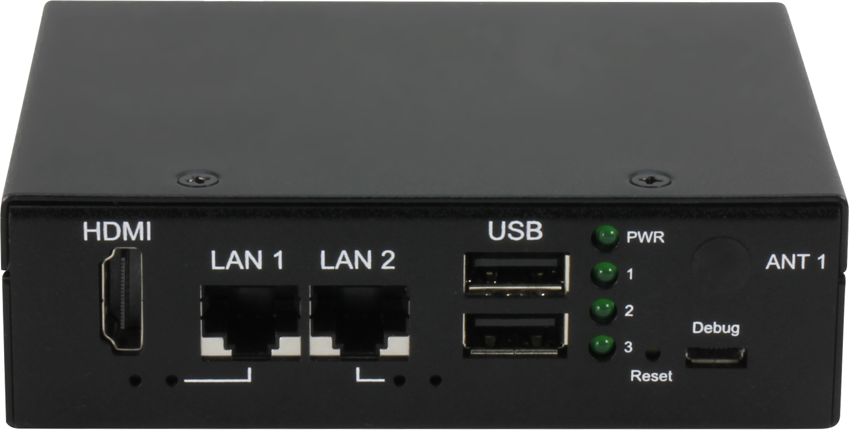
AAEON, a leading provider of compact embedded solutions, has announced two new additions to its RISC computing line: the PICO-AM62, a single board built on the PICO-ITX form factor, and the SRG-AM62, its RISC Gateway system counterpart.
Both the PICO-AM62 and SRG-AM62 represent a new approach from AAEON’s RISC Computing Division, powered by Texas Instruments™ AM62x Sitara™ Processors. These processors consist of a quad-core Arm® Cortex®-A53 CPU, single-core Arm® Cortex®-M4F MCU, and integrated GPU support.
The new product line stands out for its cost-efficiency and reliability. Both the PICO-AM62 single-board and the compact SRG-AM62 Gateway System are available in SKUs with a wide temperature tolerance of -40°C to 85°C and a power input range of 9V to 36V. The products are based on Texas Instruments™ processors, which are highly scalable and have a 20-year lifespan. This influenced AAEON’s vendor choice and should attract customers looking for cost-effective, durable IoT solutions. The environmental ruggedness of both the PICO-AM62 and SRG-AM62 makes them well-suited for deployment in challenging environments, such as in-vehicle digital clusters or industrial applications.
At both board and system levels, the platform offers dual LAN ports, camera, and sensor support. These features, combined with their compact dimensions, make them strong candidates for applications such as building access monitoring. Additionally, both products host an HDMI 1.4b interface. The PICO-AM62, in particular, includes an LVDS connector for display output, which is well-suited for human-machine-interface (HMI) use.
Wireless communication, such as Wi-Fi and 4G/LTE, is also available via full and half-size mini cards. Both products also feature a multipurpose I/O connector for industrial control functions such as RS-232/422/485, CANBus, UART, GPIO, and I2C. Leveraging this versatility, it is easy to see how the products could serve as a flexible foundation for low-cost industrial automation devices. AAEON notes that the PICO-AM62 hosts additional serial configuration options. Combining its multipurpose I/O connector with two pin headers, users can pair two RS-232/422/485 interfaces with two CAN-FD, four full RS-232/422/485 by BOM, all the way to four RS-485 alongside dual UART.
For detailed specifications and more information about the PICO-AM62 & SRG-AM62, please visit https://www.aaeon.com/en/ or contact your AAEON representative via AAEON’s dedicated contact form.