Reviewing URVE Board Pi powered by Rockchip RK3566

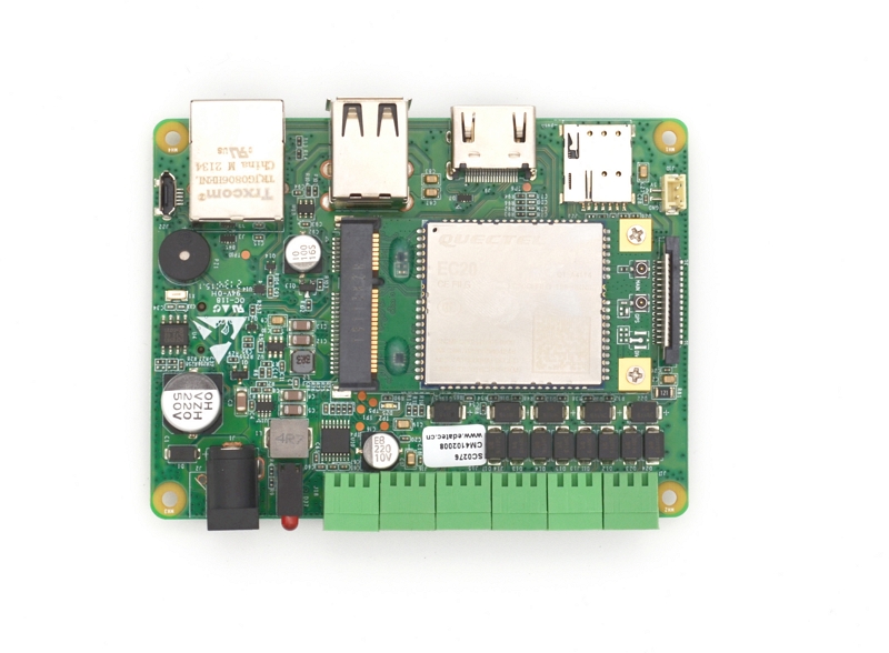
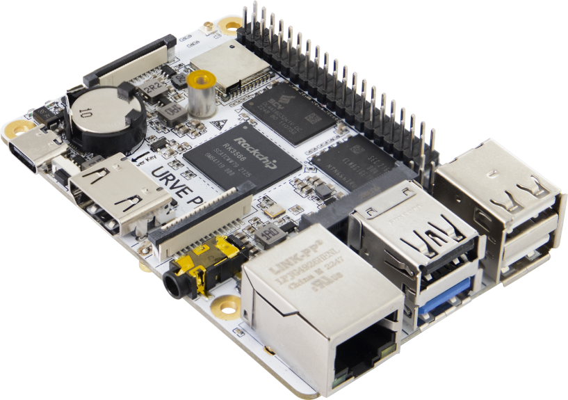
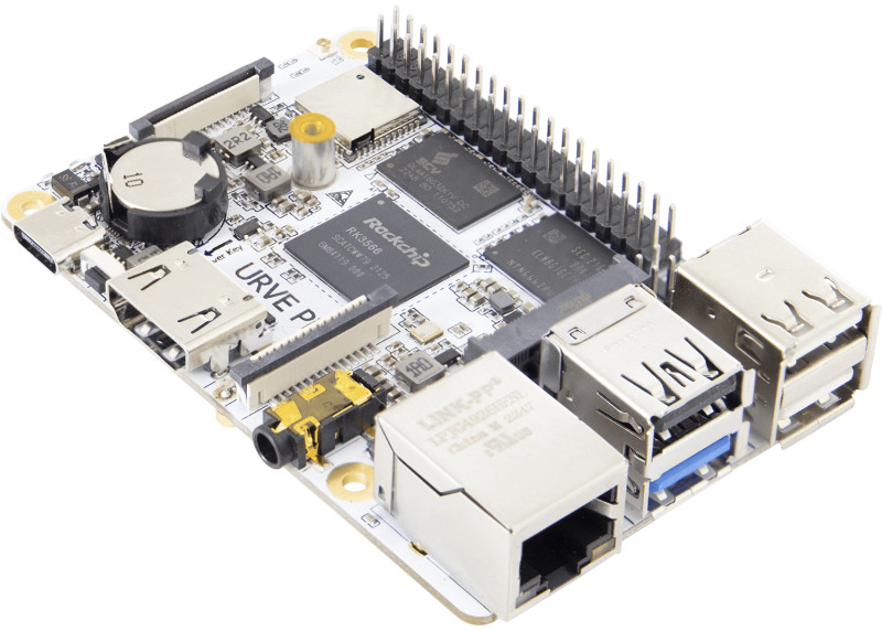
URVE Board Pi is a compact credit card-sized single-board computer (SBC) with a 1.8GHz processor, 2GB of RAM, eMMC, an M.2 connector, Gigabit Network, Wifi, and Bluetooth 4.2. It is possibly the complete all-in-one SBC. If you want to build a home NAS and store your files and photos at home, you need something like this board with an external drive. The big benefit is that the URVE Board Pi doesn’t need a bulky drive because it has an M.2 SSD connector built in. Also, it has a 1Gb network, so the speed of data transfer over the network won’t be an issue.

It also has Wi-Fi, Bluetooth 4.2, and the standard USB 2.0 and 3.0 ports, so you can connect everything you need. You might want to set up your Home Assistant system at home. The URVE Board Pi is an excellent option because it has many useful features. The URVE Board Pi is a very sturdy board that is ready for all kinds of applications, such as storage or network applications, or if you want to build a powerful arcade game emulator.

Specifications:

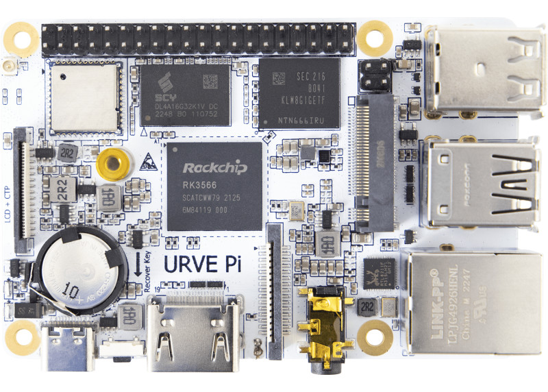
  • It is powered by Rockchip RK3566 Quad Core Cortex™ – A55 with a CPU Speed of around 1.8 GHz Quad Core (4-core), and the operating system is Android 11 / Linux Debian 11.
  • It has a memory of 2GB LPDDR4 RAM and 8GB eMMC SSD.
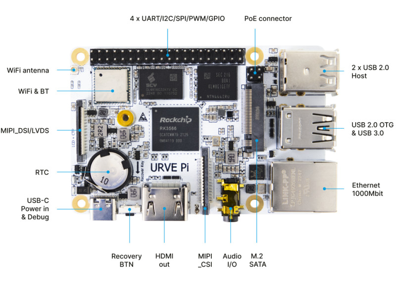
  • The graphics controller is Mali-G52: HDMI 2.0 with HDCP 1.4/2.2, up to 4K @60fps, with 4 line MIPI DSI to 2560 x 1440 @60Hz, LVDS to 1920 x 1080 @60Hz Support and HDMI V2.0, sound sync-output is the Multimedia.
  • Network with 1000 Mbit/s Ethernet and 2.4G/5G WiFi (802.11 a/b/g/n/ac), Bluetooth 4.2.
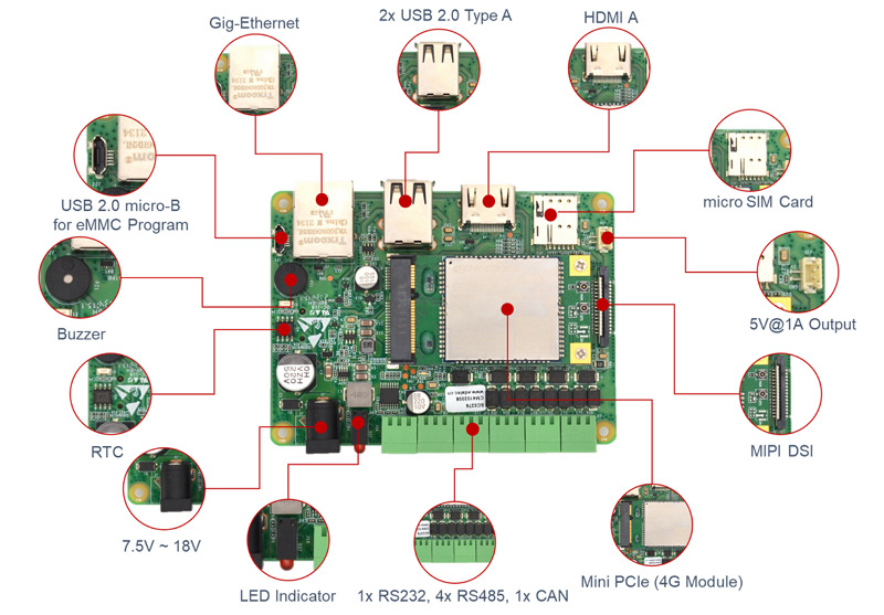
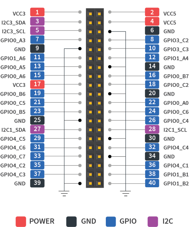
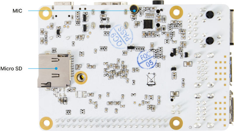
  • It has 1 x HDMI 2.0, 1 x MIPI DSI, 1 x MIPI Input CSI, 1 x LVDS, 2 x USB 2.0, 1 x USB 3.0, 1 x USB-C (Power connector 5V/2A) & Debug, 1 x USB 3.0, 1 x PCIE/M.2 SSD, 3 x I2C (do 400kbit/s) 1 x MicroSD, 1 x Stereo, 1 x Microphone input, 1 x 1000 Mbit/s Ethernet RJ-45, 2 x SPI, 4 x UART (RS232) 1 x ADC by headphone input, 10 x PWM, 1 x PoE connector I/O slots.
  • It has an operating temperature of 0°C ~ 70°C (no condensation) with a passive cooling system and vibration resistance with no moving elements.
  • Its dimensions is 85 x 56 mm.
  • It weighs around 50 g.
  • URVE multimedia software is the control software.

The product page contains a detailed specifications.

The company offers “URVE multimedia software” created for digital signage applications together with Android 11 and Debian 11 OS images for the board. The built-in eMMC flash storage, the real-time clock (RTC) with a backup battery, the M.2 SSD socket, and a 0.8 TOPS NPU that enables running accelerated machine learning or artificial intelligence workloads without an external AI accelerator are the added features compared to the Raspberry Pi 3 or 4 SBC. Beyond merely supporting DSI displays, the MIPI DSI can also accommodate an LVDS display.

You can purchase the URVE Board pi from BricoGreek for the price of 94,95 Euros.

The nanoCH32V003 is a RISC-V dev board available for $1.50

nanoCH32V003 is a development board that was created by MuseLab and is based on CH32V003F4U6, which was manufactured by QinHeng. On the board are a reset button, an LED, and a crystal oscillator that operates at 24 MHz. The 1-wire serial debug interface (SDI) is supported, and all of the general-purpose input/output (GPIO) pins are led out. This makes it easy for developers to create and prototype.

It is based on WCH’s CH32V003; unlike the nanoCH32V305 and the nanoCH32V203 boards also developed by MuseLab, the new RISC-V development board has a maximum frequency of 48MHz, 16KB Flash, and 2KB SRAM. It can be programmed using MounRiver or other open-source toolchains.

32-bit general-purpose RISC-V MCU-CH32V003:

Based on the QingKe RISC-V2A core design of an industrial-grade general-purpose microcontroller, the CH32V003 series supports a main system frequency of 48MHz, has a wide voltage range, a 1-wire serial debug interface, low power consumption, an ultra-small package, etc. CH32V003 series built-in a group of DMA controllers, a group of 10-bit ADCs, a group of op-amp comparators, multiple timers, and standard communication interfaces like USART, I2C, SPI, etc.

CH32V003 series features QingKe 32-bit RISC-V2A processor, supporting two levels of interrupt nesting with a maximum 48MHz system central frequency and 2KB SRAM, 16KB Flash. Its power supply voltage is 3.3/5V with power on/off reset, programmable voltage detector, 1 group of 1-channel general-purpose DMA controller, 1 group of op-amp comparator, 1 group of 10-bit ADC, 1×16-bit advanced-control timer, 1×16-bit general-purpose timer, 2 WDOG, 1×32-bit SysTick, 1 USART interface, 1 group of I2C interface, 1 group of SPI interface, 18 I/O ports, mapping an external interrupt, 64-bit chip unique ID and a 1-wire serial debug interface (SDI).

CH32V003 can only be programmed by WCHLink-E through the SDI interface (1-wire serial debug interface). If you are buying the board for the first time, the product page suggests that you buy it with WCHLink-E. Visit the GitHub link provided here for a more in-depth description. Additionally, it states that the MounRiver Studio IDE development environment, which supports Windows/Linux/Mac, is officially provided by WCH.

On AliExpress and Tindie, the nanoCH32V003 Development Board is offered for $1.50.

It is best to purchase the available nanoCH32V003 Dev board + WCH LinkE and USB Type-C cable bundle, as advised on the product page.

Featuring T-Display-S3 with ESP32-S3 and 1.9 inch Color Display

T-Display-S3 is a development board that has ESP32-S3 as the main control chip. It features a color LCD screen that is 1.9 inches in size and two buttons that may be programmed. The connectivity is made possible by the use of the I8080 interface. It also maintains the same design and layout as the T-Display. The LCD Display Development Board has WIFI Bluetooth 5.0  and a wireless module with 170 x 320 resolution. The product page states that it is recommended to use a USB 2.0 cable (USB A-USB C cable) and that it is compatible with ST7789.


A new component has been introduced as part of the T-Display series. It comes equipped with the most up-to-date ESP32-S3 (which supports Wi-Fi 802.11, BLE 5, and BT mesh). The screen has also been widened from its previous measurement of 1.14 inches to its current measurement of 1.9 inches, and a plate made of acrylic has been added to fix it. This will be the second iteration of the LILYGO model display to incorporate a permanently attached acrylic plate. The T-Display series’ design is carried over into the overall aesthetic of the product.

Specifications:

  • The ESP32-S3R8 Dual-core LX7 microprocessor provides the necessary processing capability.
  • The programming platform consists of Arduino-ide as well as Micropython.
  • A 1.9-inch LCD diagonal Full-color TFT Display is an appealing characteristic of this product.
  • It offers a Resolution of 170 (H)RGB x320 (V) and Utilizes an 8-Bit Parallel Interface.
  • The ST7789V drive chip is the one that is used.
  • It has 16MB of Flash storage and 8MB of PSRAM, and it also has IO04 for detecting the voltage of the battery.
  • Moreover, there is an IO14 button, a boot button, and a reset button supplied.
  • Wireless connectivity is provided by Wi-Fi 802.11, Bluetooth Low Energy 5 (BLE 5), and BT mesh.
  • 3.3 volts is the working power supply.
  • It supports STEMMA QT/Qwiic and the JST-SH 1.0mm 4-PIN connectors.
  • The connector that is utilized is a JST-GH 1.25mm 2-PIN.
  • Dimension is 62mm x 26mm x 10mm.


The Arduino IDE, MicroPython, or the ESP-IDF framework are all listed as supported development environments for the board by LilyGO. However, the Github repository only provides fundamental instructions for getting started with the Arduino IDE and PlatformIO. T-Display-S3 can be purchased through LILYGO, Amazon, and Aliexpress.

AmpRipper 4000 is a New Battery supply Board for Raspberry Pi & Arduino

Kickstart Design is preparing to launch a campaign on Kickstarter for the AmpRipper 4000, their next-generation battery supply board for Raspberry Pi, Arduino, and other electronic projects, which is set to launch soon – boasting a significant upgrade from the AmpRipper 3000 design.

In September 2021, the AmpRipper 3000 was unveiled, utilizing the Monolithic Power MP2624 to convert almost any lithium-ion or lithium-polymer battery with an output of 3.7V to 4.2V into a power source for DIY electronic projects. However, the AR4000 makes use of Monolithic’s MP2617 and MP3424 boost converter, which can provide up to 4A of power – a third more than the previous model. For those who don’t need a USB, the power output is also available on through-hole terminals.

Regarding the project, the company says:

‘‘As makers, we were tired of dealing with the unreliable, underpowered, inaccessible battery modules that are currently available. So we made our own, the AmpRipper 3000, and sold them to makers suffering from the same headaches. Since the beginning, our goal with the AmpRipper series has been to provide makers with powerful, durable, intelligent battery charge & boost modules. Taking what we’ve learned from our first module, we designed an even better one, the AmpRipper 4000. In addition to scaling up the AmpRipper’s capabilities, we want to scale up its production’’.

The AR4000 module ensures that power to your project is not interrupted, even if the battery or charger is removed, by utilizing Mart Power Path Management Technology. It also accepts a wider input voltage range of 5-14V compared to its predecessor and is compatible with 3.7-4.2V 1S[N]P lithium-ion/polymer batteries. Additionally, the MAX17048 battery monitor allows for the monitoring of battery voltage and charge percentage via I2C. Furthermore, AR4000 offers improved accessibility with more i/o and expanded connectivity options, including USB-C and thru-hole terminals for power input and output, as well as a JST PH-2.0 connector and thru-hole terminals for the battery. The AmpRipper 4000 has the same design as its predecessor, but the USB Type-A port has been removed. The new design also features an Analog Devices MAX17048 battery monitor, which can be accessed via I2C to check the battery voltage and charge percentage. Additionally, an optional custom heatsink and fan assembly are included, which is recommended if the board is expected to be running at its highest capacity for extended periods.

Kickstart Design is launching its board on Kickstarter with a crowdfunding campaign starting in March 2021. The expected price for the original AmpRipper 3000 is under $40, and more information can be found on the Kickstart Design website, and also on Kickstarter when the campaign goes live.

EDATEC CM4 Sensing Computer For IoT & Data Acquisition applications

The Internet of Things (IoT) is changing the way we interact with the world around us by connecting devices and systems in ways that were never before possible. With the growth of IoT solutions, there is an increasing need for smart and reliable sensors to enable this new capability. CM4 Sensing IoT World by Raspberry Pi offers a comprehensive suite of intuitive, easy-to-use sensors to help you stay connected with the world around you. CM4 Sensing IoT World by Raspberry Pi is a comprehensive suite of intelligent devices and software components that allow users to measure, monitor, communicate, and control physical data in real-time. The suite includes motion detectors, environmental sensors, pressure sensors, and temperature sensors.

EDATEC CM4 Sensing is an industrial computer designed for IoT & Data Acquisition applications based on Raspberry Pi Compute Module 4. It utilizes the structural flexibility of CM4 to solve the heat dissipation problem of the CPU, wireless module, and PMU. The external antenna also improves the reliability of wireless communication, in other words, this can serve as a wireless booster for your computers.

This system can be tailored to different applications with the choice of 1GB/2GB/4GB/8GB RAM, 8GB/16GB/32GB eMMC, 2.4/5.8G dual-band WiFi, Bluetooth (optional), and external antenna functionality. For applications that demand massive data storage, users can install the operating system and store application data with eMMC, whilst also using an SD card for storing larger user data. This ultimately offers more capacity than a built-in eMMC memory, at a more cost-effective price.

CM4 Sensing offers a 4G/LTE module, 4 RS485 channels, 1 RS232 channel, 1 CAN channel, 1 Gigabit Ethernet port, an alarm buzzer, and a battery-powered real-time clock. The CM4 Sensing’s DSI Interface is fully compatible with Raspberry Pi4 Model B and supports its official 7″ touch display. It also provides 5V/1.5A power output to power the Pi Display and outputs 4K HD video via its Standard HDMI interface. CM4 Sensing is equipped with 2 USB 2.0 channels and 1 Micro USB 2.0 channel, with the Micro USB channel being for system image updates.

The CM4 Sensing is slightly larger than the Pi4 Model B, measuring 103 x 73 x  32mm, and it comes with connectors that exit from both the front and back. A 103 x 73mm x 5mm heatsink ensures optimal cooling performance for the CPU, wireless module and PMU, enabling it to function in a high-temperature environment. A series of testing has proven the CM4 Sensing to have a reliable operation at -25~60°C ambient temperatures. For extra convenience, 4 M2.5 screw holes are provided at the base of the case, enabling users to install their CM4 Sensing on other equipment or mount it on DIN rail or walls.

The CM4 Sensing is an assembled finished product. It is not recommended to disassemble the shell by yourself, because disassembling the shell by yourself will affect the warranty, except if you are a tech enthusiast, and don’t mind exploring what’s inside the device. Also note that If you purchase the 4G module, it defaults to the Chinese version without GPS. Also note that If you purchase the 4G module, please specify the 4G version (EU, US or AU etc). If you need to equip other models, please contact customer service to confirm if it is compatible.

You can find several variants of the EDATEC CM4 Sensing industrial computer at https://www.edatec.cn/en/distributor/. For more CM4 Sensing technical data, please click EDATEC’s online datasheet: https://www.edatec.cn/en/elpc/cm4-sen.html

And if you want to learn more about EDATEC and our robust embedded HW solutions for  industrial applications based on Raspberry Pi including custom design and manufacturing capability, please visit EDATEC website: https://www.edatec.cn/ For more general information, please contact: support@edatec.cn

Taoglas Invisible Antenna Unlocks IoT Innovations with Covert Connectivity

Taoglas’ new transparent flex antennas offer a clear alternative to opaque antennas for covert cellular, Wi-Fi, and GNSS connectivity in innovative IoT applications.

The future of antennas is clear

Taoglas®, a trusted provider of antennas and IoT components that helps solve complex engineering problems, announces three new invisible antennas supporting cellular, Wi-Fi, and GNSS technologies. With simple “peel and stick” mounting to any nonmetal surface such as plastic, glass, and screens, the paper thin, ultra-lightweight TFX series offers a clear alternative to standard opaque antennas for use in mobility, public infrastructure, medical devices, transportation, and emerging IoT applications.

The TFX62.A, TFX257.A, and TFX125.A can be used standalone or in a custom combination to enhance cellular, Wi-Fi, and GNSS antenna installations respectively. Each antenna comes with an adhesive applied and has an enclosed carrier terminated with a FAKRA connector for easy installation. The new series leverages a sub-mm thick hybrid transparent conductive film that offers designers an invisible antenna solution with the performance, reliability, and form factors of opaque antennas.

Example use-cases include

  • EV Chargers and Parking Meters – On-screen placement eliminates the need for external antennas on metal enclosures.
  • Smart Buildings – Antenna placement on windows with cable connections to routers hidden in the walls improves a building’s aesthetic.
  • Transportation Vehicles – Covertly installed antennas replace large external antennas for in-vehicle connectivity.

TFX Series Features & Benefits

  • Invisibility – Ultra-low-profile, transparent film enables concealed antenna placement and provides access to unavailable physical spaces.
  • Robust manufacturing technology – Heat-resistant and UV-protected transparent material with a seamless click-connect works without soldering on all shapes and antenna configurations.
  • Customizable, modular design – GNSS, Wi-Fi, and 5G/4G cellular options with or without FAKRA connectors support higher levels of wireless complexity, including MIMO and mmWave.

Come see Taoglas at Mobile World Congress 2023 in Barcelona, Spain and Embedded World 2023 in Nuremberg, Germany or contact Taoglas to learn more.

ESP32-MPY-Jama MicroPython IDE Programs ESP32 MCUs

MPY-Jama, created by Jean-Christophe Bos, is a great tool for those looking for a balance between heavy and light IDEs that support MicroPython. MicroPython is an open-source interpreter that runs on embedded hardware, allowing programmers to write easy-to-understand programs for microcontrollers like Espressif’s ESP32 quickly. MPY-Jama has an IDE, a REPL terminal, Wi-Fi tools, and other features that make working with the ESP32 and MicroPython much simpler.

Bos provides pre-compiled binaries for macOS and Windows for ESP32 MPY-Jama, a C-python program. For Linux, you can either run it directly or follow Bos’ instructions to build a binary tailored to your distro using pyinstaller. The ESP32’s IDE section looks, at and feels like the Arduino 2.0 IDE, with files arranged as tabs and saved directly to the ESP32. Unfortunately, there is no code completion when writing MicroPython instructions, but the color theme and syntax highlighting are well done. Additionally, the integrated REPL (read-evaluate-print-loop) terminal allows users to switch between writing code and directly testing functions.

Other IDEs, such as Thonny and Mu, have the essential features, but ESP32 MPY-Jama stands out due to its additional capabilities. For instance, it comes with a suite of tools called Jama Funcs, which are pre-built functions to help configure the device. Furthermore, the Wi-Fi connection tools make it simple to search for available networks and connect MicroPython to them.

The GUI has a widget in the bottom-left corner that always displays real-time information such as RAM usage, temperature sensor, and how long the board has been running. Additionally, the System Info section provides additional details that can be accessed without having to type commands on the REPL, such as the version of code on the device, as well as a real-time read-out of the GPIO pin state.

In order to use the firmware tools to help with updating the firmware, ESP32 MPY-Jama must have access to the esptool.py toolchain, which can be installed through pip, the python package manager. If you are a Windows user, you may need to add the directory path of the installed EXEs to your environmental variables so that ESP32 MPY-Jama can locate the tool. For instance, “esptool.py.exe” may be installed in “%AppData%\Roaming\Python\Python39\Scripts” (the location may vary depending on your system and Python version). He also provided details on how to clone the repository and run from the source. It has been tested on Ubuntu 22.04, but should work with minor adjustments on similar distributions.

You can find more information in the GitHub repository.

Sierra Wireless Announces New 5G LPWA HL7900 Module Integrating Sony’s Altair ALT1350 Chipset

Powering next-gen LPWA solutions with an ultra-low power 5G cellular+ module for IoT

Sierra Wireless, a subsidiary of Semtech Corporation and world leading IoT solutions provider, today announced its latest HL Series LPWA module, the 5G HL7900, for next-generation use cases needing ultra-low power, increased device longevity and support for 3GPP’s latest 5G standards. The module uses new ALT1350 chipset from Sony Semiconductor Israel (Sony) which is claimed by Sony to be the world’s first cellular chipset to additionally enable unlicensed spectrum communications protocols, as well as satellite connectivity.

“Not only does Sony’s Altair ALT1350 chipset enable hybrid connectivity options, but its advanced architecture sets a new bar in ultra-low power consumption,” said Dima Feldman, VP of Product Management and Marketing, Sony Semiconductor Israel. “Its optimized standby mode (eDRX) reduces power consumption by 80% when compared to the current generation, with battery-operated devices benefitting from 4 times longer battery life for typical use cases. Integrated into Sierra Wireless’ latest 5G HL7900 module,” continued Mr. Feldman, “it answers the evolving and rapidly expanding needs of the cellular LPWA IoT market, enabling faster development, additional functionality, new use cases and reduced costs for customers. We’re thrilled to be continuing our partnership with Sierra Wireless to enable the next-generation of innovative LPWA solutions.”

Building on the success of Sierra Wireless’ existing HL78 Series LPWA modules, the HL7900 with its ALT1350 chipset not only offers best-in-class battery life and enhanced security, but sub-GHz and 2.4GHz integrated radios enable low-power IoT protocols, offering customers the flexibility of multiple connectivity options with enhanced coverage, and reduced costs. The module will also support 3GPP’s latest releases 15, 16 and 17 for LTE-M/NB-IoT, that will enable it to support evolving network configurations and new features over time.

“Sierra Wireless continues to lead with one of the most innovative and secure LPWA module portfolios on the market,” said Tom Mueller, EVP of Semtech’s IoT System Products Group. “The new 5G LPWA HL7900 not only provides ultra-low power and network future proofing, but it also enables next-generation use cases with its integrated low-power MCU for customer hosted edge applications, and the ability to enable hybrid connectivity with multiple protocols supported on one SKU. All in addition to offering a high level of end-to-end security. Its ability to allow deployments that utilize universal connectivity with edge processing and multiple location technologies is a real game changer for IoT.”

Highlights

  • The 5G HL7900 module utilizes Sony’s ALT1350 chipset, resulting in optimized standby mode and an 80% reduction in power consumption. For typical use cases, this translates to a four times longer battery life.
  • The module’s ultra-low power and network future-proofing features make it an excellent choice, along with the integrated low-power MCU for customer-hosted edge applications, and the ability to enable hybrid connectivity with multiple protocols supported on one SKU.
  • The cellular IoT market’s global value is expected to reach $61 billion by 2026, and with the growth of 5G and cellular LPWA technologies, the demand for Sierra Wireless’ 5G HL7900 module will continue to rise.

Sierra Wireless’ HL78 Series Module Portfolio – The Next-Generation of LPWA

Sierra Wireless’ HL Series modules including the HL7810, HL7812 and the new HL7900, support multi-mode Cat-M1 and Cat-NB2 networks around the world. They offer an ultra-low power consumption for their class, reducing operational and device maintenance costs and making them ideal for battery powered and low power deployments that require deep area coverage such as smart energy solutions, smart city applications, asset tracking, commercial buildings, manufacturing, healthcare, utilities and agriculture. Further, security is designed in from the start, with encrypted keys stored in a secure element for an added layer of protection from the edge to the cloud.

Cellular IoT Market to Reach $61 Billion Globally by 2026, Driven by 5G & Low-power Solutions

A 2022 study by Juniper Research found that the global value of the cellular IoT market will reach $61 billion by 2026, rising from $31 billion in 2022. It identified the growth of 5G and cellular LPWA (Low-power Wide Area) technologies as key to this 95% increase over the next few years. According to the study, LPWA solutions are predicted to be the fastest-growing cellular IoT technologies with LPWA connections expected to grow 1,200%.

Availability

Sierra Wireless’ HL7900 module is expected to sample to lead customers later in 2023.

For more information, visit: https://www.sierrawireless.com/iot-modules/lpwa-modules/

To contact the Sierra Wireless Sales Team, call +1 877-687-7795 or visit http://www.sierrawireless.com/sales

Debugging Pico using SWD and UART with the new Raspberry Pi Debug Probe, at just $12

rpi-debug-probe-jst

The Raspberry Pi Debug Probe is a comprehensive USB-to-debug kit that provides the necessary hardware for solderless, plug-and-play debugging. It is inspired by the trend where electronics enthusiasts used one Raspberry Pi Pico to debug programs running on another Pico board and features Raspberry Pi’s RP2040, a dual-core Arm Cortex-M0+ microcontroller with clever Programmable Input/Output (PIO) blocks.

The Raspberry Pi Debug Probe is a compact board that provides a micro-USB connection at one end and headers for UART serial and SWD debugging at the other – plus an unpopulated three-pin header to access SWD on its RP2040 if required. To cover the vast majority of debugging use cases, the Raspberry Pi Debug Probe is a kit comprising the Pico Debug Probe hardware in a dedicated plastic case together with a USB cable and three types of debug cable:

  • USB cable
  • Three debug cables
    • 3-pin JST connector to 3-pin JST connector cable
    • 3-pin JST connector to 0.1-inch header (female)
    • 3-pin JST connector to 0.1-inch header (male)

It is designed to simplify debugging and programming on Raspberry Pi Pico and RP2040 with a range of host platforms, including Windows, Mac, and Linux, despite the GPIO header’s unavailability to connect directly to the Pico’s serial UART or SWD port.

rpi-debug-probe-wires

Debugging: Why and How

Debugging is an essential aspect of software development. It can help to identify and fix issues in a timely and efficient manner. Some everyday use cases for debugging in the Raspberry Pi Pico include:

  • Code optimization: Debugging can help identify performance bottlenecks that could be optimized to improve the overall efficiency and speed of the system.
  • Troubleshooting: Debugging can help identify and isolate issues with the code or hardware. It can be handy when developing complex systems that involve multiple components.
  • Testing: Debugging ensures that the code works as expected and the system functions correctly. It is crucial in safety-critical applications.
  • Integration: Debugging can help to identify and resolve issues that may arise when integrating third-party libraries or components into the system.

To support debugging, the Raspberry Pi Pico includes a built-in USB port that can be used for programming and debugging. It also supports a range of software development tools, including the C/C++ compiler and IDEs like Visual Studio Code, to write, compile, and debug code for the Pico. Additionally, the Pico includes a built-in LED that can be used for status indicators and debugging purposes.

Debugging the Raspberry Pi Pico can be done using various methods and tools, depending on your preferred development environment and programming language.

One common approach to debugging the Pico is printf-style debugging by printing data to the console for diagnosis. Raspberry Pi Pico has a UART interface to send and receive data over a serial connection. You can use a USB-to-serial adapter to connect the Pico to your computer and view the output in a terminal program like PuTTY.

Another approach is to use a hardware debugger, such as the Pico Debug Probe to connect to the Pico’s SWD interface and perform complex debugging tasks like setting breakpoints, single-stepping through code, and examining memory and register values. To use a hardware debugger, you’ll need to connect the debugger to the Pico’s SWD interface, which is available on the board’s GPIO header.

In the case of MicroPython or CircuitPython on the Pico, the built-in REPL (Read-Evaluate-Print Loop) can be used to interact with the board and diagnose issues in real time.

Finally, many IDEs also offer built-in debugging tools for Raspberry Pi Pico, including VS Code, Arduino IDE, and Raspberry Pi Pico C/C++ SDK. These tools can provide a streamlined debugging experience with features like code stepping, variable inspection, and conditional breakpoints.

Raspberry Pi Debug Probe

The Pico Debug Probe contains all the hardware required for debugging the Pico code in various methods listed above. The Raspberry Pi Debug Probe exposes the SWD signals on a three-pin JST connector, conforming to the Raspberry Pi Debug Connector Specification. The Debug Probe also provides adapter cables to connect to the debug connector on Raspberry Pi Pico and Pico W without soldering to the breadboard. The Raspberry Pi Debug Probe also functions as a USB serial adapter over the same USB connection as the SWD bridge. It exposes the UART signals on a second three-pin JST connector.

According to Raspberry Pi, the board is primarily designed to be used with Raspberry Pi Pico and Pico W. Nevertheless, it is also compatible with any Arm-based microcontroller which supports SWD and operates at 3.3V logic.

The Debug Probe is based on Raspberry Pi Pico hardware. It runs the open-source Raspberry Pi Picoprobe software, which allows a Pico and RP2040 to be used as USB to SWD and UART bridge. In addition, Raspberry Pi Pico or Pico W can be coupled with Picoprobe firmware to convert it into a device functionally equivalent to the Raspberry Pi Debug Probe, only lacking in the handy JST connectors.

The form factor of Pico Debug Probe is 22mm X 32mm, with features like USB to two-wire serial debug bridge, USB to UART bridge and follows the Raspberry Pi 3-pin Debug connector specification. Its nominal I/O voltage is 3.3V with operating temperature at -20C to 70C.

To know more about the product, please visit Buy a Raspberry Pi Debug Probe – Raspberry Pi

AAEON Harnesses More Power, Efficiency, and Expandability with the new BOXER-6451-ADP

AAEON makes it easier to deploy powerful, space-efficient solutions without sacrificing functionality.

AAEON, a provider of elite embedded solutions, has expanded its line of fanless embedded box PCs powered by 12th Generation Intel® Core™/Celeron® processors (formerly Alder Lake-P U15) with the release of the BOXER-6451-ADP.

Boasting the smallest chassis of AAEON’s trifecta of new box PCs utilizing the latest Intel technology, the BOXER-6451-ADP offers 10 cores and 12 threads of processing power in a compact 7.48″ x 4.37″ x 2.5″ (190mm x 111mm x 63.5mm) model. AAEON believes this will help to bring compact, flexible solutions such as smart kiosks and charging stations to market with ease.

BOXER-6451-ADP highlights:

  • High-speed I/O: USB 3.2 x 3, 2.5 GbE LAN, RS-232/422/485 x 4
  • 5G, Wi-Fi, and NVMe support
  • Compact chassis: 190mm x 111mm x 63.5mm
  • Alder Lake-P U15 Processors
  • New, innovative heat dissipation system

Adding to the BOXER-6451-ADP’s suitability to smaller deployment spaces is its innovative new heat dissipation framework, which has seen AAEON replace the tubular heat pipe typically used to conduct heat from a PC’s CPU to its heatsink with a flattened pipe to both increase its conduction area and accelerate heat transfer. This enables the system to maintain thermal regulation during periods of high workloads.

Despite its small dimensions, the BOXER-6451-ADP contains a dense, high-speed I/O featuring three USB 3.2 ports running at 10Gbps, one 2.5 GbE LAN port, and four COM ports with RS-232/422/485 support. Combined with the latest Intel technologies such as Intel® IPU 6.0 and Intel® DL Boost, the BOXER-6451-ADP appears to be an excellent base for solutions requiring high-speed peripheral device connectivity, such as AMR.

Finally, the BOXER-6451-ADP offers an upgrade compared to its BOXER-6400 series predecessors when it comes to expansion. 5G, Wi-Fi, and NVMe are supported via M.2 E, B, and M Keys, which AAEON believes will provide more flexible deployment options for industrial applications, such as AI-IoT gateway controllers and robotic arms.

For more information about the BOXER-6451-ADP, please visit our product page or contact an AAEON representative directly.

TOP PCB Companies