

The Stereo Tape Head Preamplifier kit is based on LA3161 IC from SANYO.
Specifications
- Power supply – 9 ~ 12 VDC @ 20 mA
- Output power – upto 200 mW
- Input Resistance – 100 KΩ (Typ), Load Resistance – 10 KΩ (Typ)
- Low noise, good ripple rejection owing to the on-chip voltage regulator
- Berg pins for connecting power supply, input and output
- Power-On LED indicator
- Four mounting holes of 3.2 mm each
- PCB dimensions 51 mm x 54 mm
Schematic
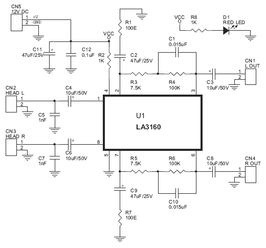
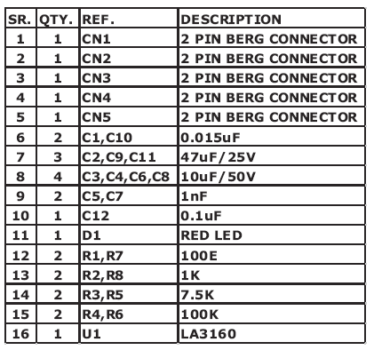
Parts List


The Tiny Audio Amplifier kit is a good choice for battery operation. It is based on LM386 IC.
Specifications
- Power supply – 6 – 12 VDC
- Output power – 1 W, 8 Ohm
- The quiescent power drain is only 24 mW when operating from 6 VDC
- Self-centering output quiescent voltage
- Onboard PRESET to adjust volume
- Terminal pins for connecting power supply, audio signal and speaker
- Power-On LED indicator
- ON/OFF PCB mounted slide switch for power supply
- Four mounting holes of 3.2 mm each
- PCB dimensions 44 mm x 44 mm
Schematic

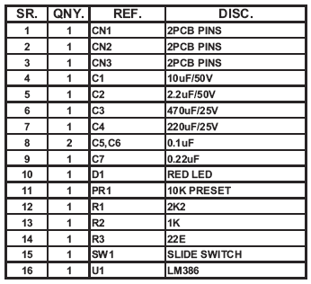
Parts
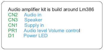
Inputs – Outputs configuration
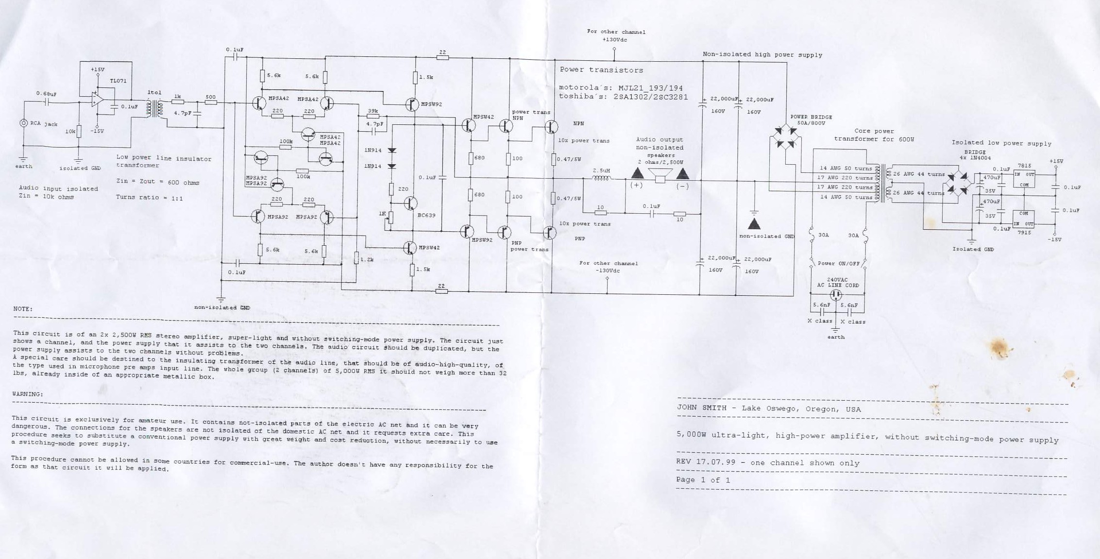
This circuit is of an 2x 2,500W RMS stereo amplifier, super-light and without switching-mode power supply. The circuit just shows a channel, and the power supply that it assists to the two channels. The audio circuit should be duplicated, but the power supply assists to the two channels without problems.
A special care should be destined to the insulating transformer of the audio line, that should be of audio-high-quality, of the type used in microphone pre amps input line. The whole group (2 channels) of 5,000W RMS it should not weigh more than 32 lbs, already inside of an appropriate metallic box.
WARNING:
This circuit is exclusively for amateur use. It contains not-isolated parts of the electric AC net and it can be very dangerous. The connections for the speakers are not isolated of the domestic AC net and it requests extra care. This procedure seeks to substitute a conventional power supply with great weight and cost reduction, without necessarily to use a switching-mode power supply.
This procedure cannot be allowed in some countries for commercial-use. The author doesn’t have any responsibility for the form as that circuit it will be applied.
REV 17.07.99 – one channel shown only
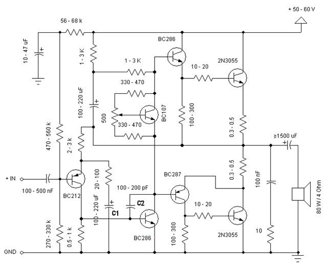

Simple and low cost. The optimal supply voltage is around 50V, but this amp work from 30 to 60V. The maximal input voltage is around 0.8 – 1V. As you can see, in this design the components have a big tolerance, so you can build it almost of the components, which you find at home. The and transistors can be any NPN type power transistor, but do not use Darlington types… The output power is around 60W.
Comments
- capacitor C1 regulates the low frequencies (bass), as the capacitance grows, the low frequencies are getting louder.
- capacitor C2 regulates the higher frequencies (treble), as the capacitance grows, the higher frequencies are getting quieter.
- this is a class B amplifier, this means, that a current must flow through the end transistors, even if there is no signal on the input. This current can be regulated with the 500Ω trimmer resistor. As this current increases, the sound of the amplifier gets better, but the end transistors are more heating. But if this current decreases, the transistors are not heating so much, but the sound gets worse…
Jacint Chapo – 14/9/2005
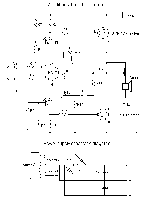

This is a very simple, low cost, Hi-Fi quality power amplifier. You can build it 5 ways, like its shown in the table (from 20 W to 80 W RMS).
Comments
- The first thing that you must do, is to measure the end transistors (T3 and T4) amplifying coefficient, the hfe or β. If their disagreement is bigger than 30 %, the amplifier would not give a clear sound. I used MJ3001 and MJ2501 transistors, and this disagreement was around 5%.
- Before the first turning on you must short circuit the inputs of the amp, and put a mA-meter on the output, than turn the amplifier on, and tune the R13 pot, to decrease the DC current on the output, to some uA-s, or in a lucky situation to zero. I was able to decrease it to 10 uA.
Parts
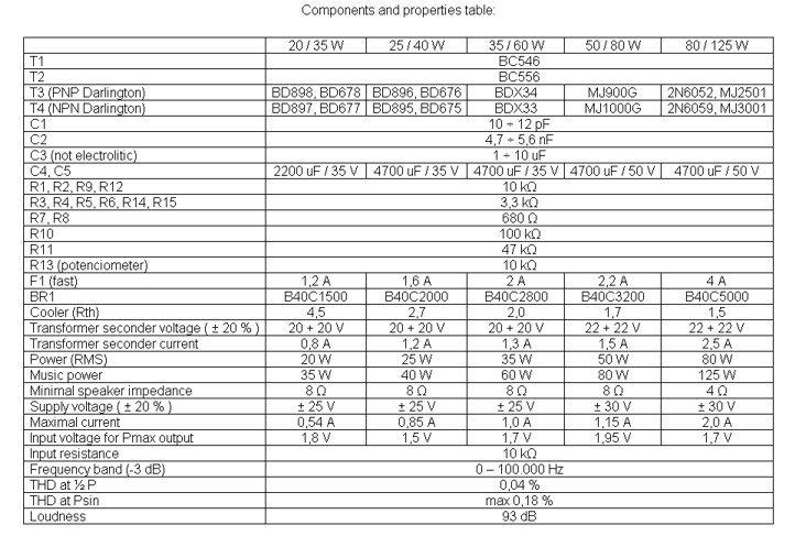
I am very contented with this amplifier. It gives a very good sound quality. Have fun with it!
Jacint Chapo – 6/5/2005
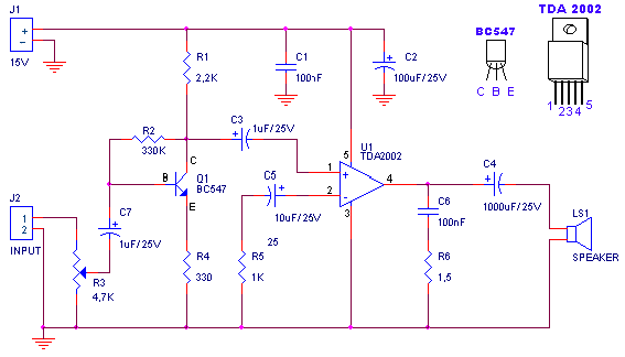

Characteristics
- Input Voltage: 15V
- Output Power: 4,2Wrms @ 4Ohm
- Minimal input signal: 94mVp-p with preamplifier, 0,65Vp-p without the preamplifier
Parts
| R1 |
2,2K |
| R2 |
330K |
| R3 |
4,7K – logarithmic potentiometer |
| R4 |
330K |
| R5 |
1K |
| R6 |
1.5Ohm |
| C1, C6 |
100nF polyester |
| C2 |
100uF/25V electrolytic |
| C3, C7 |
1uF/25V electrolytic |
| C4 |
1000uF/25V electrolytic |
| C5 |
10uF/25V electrolytic |
| Q1 |
BC547 |
| U1 |
TDA2002 |
| LS1 |
speaker |
Notes
Output power related to speaker impedance
| LS1 |
Output Power |
| 2Ω |
6,5 Wrms |
| 4Ω |
4,2 Wrms |
| 6Ω |
3 Wrms |
| 8Ω |
2,25 Wrms |
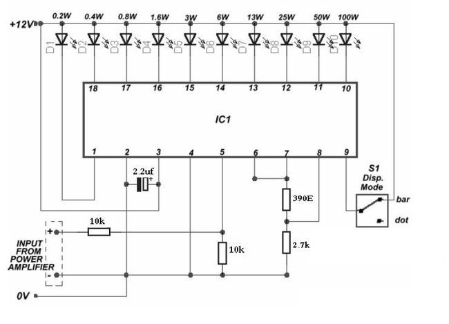

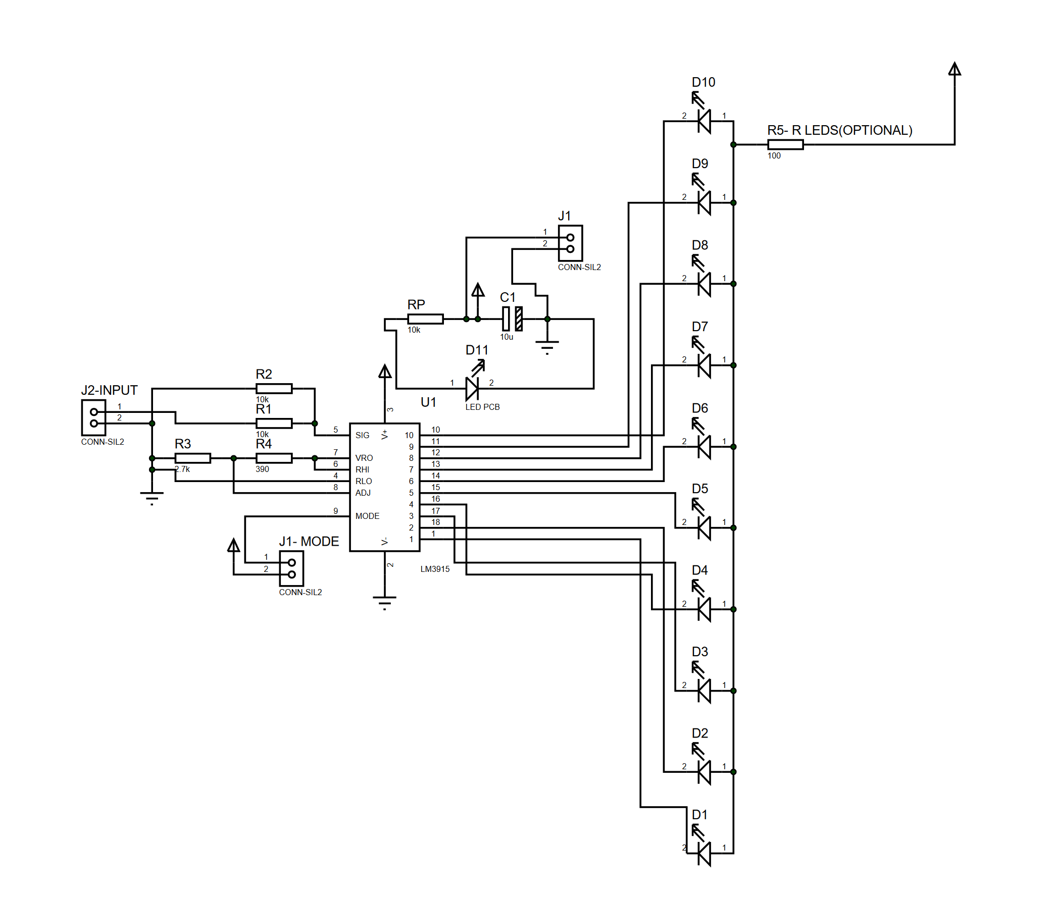
This nifty sound level meter is a perfect one-chip replacement for the standard analog meters. It is a completely solid state and will never wear out. The whole circuit is based on the LM3915 audio-level IC and uses only a few external components.
Parts
| C1 | 2.2uF 25V Electrolytic Capacitor |
| R1 | 1K 1/4W Resistor |
| D1 | 1N4002 Silicon Diode |
| LED1-LED10 | Standard LED or LED Array |
| U1 | LM3915 Audio Level IC |
| MISC | Board, Wire, Socket For U1 |
Notes
- V+ can be anywhere from 3V to 20V
- The input is designed for standard audio line voltage (1VP-P) and has a maximum input voltage of 1.3V
- Pin 9 can be disconnected from the ground to make the circuit use a moving dot display instead of a bar graph display
Additional Circuit
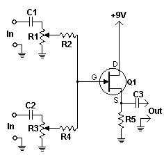

This simple circuit mixes two or more channels into one channel (eg. stereo into mono). The circuit can mix as many or as few channels as you like and consumes very little power. The mixer is shown with two inputs, but you can add as many as you want by just duplicating the “sections” which are clearly visible on the schematic.
Parts
| Part |
Total Qty. |
Description |
| R1, R3 |
2 |
10K Pot |
| R2, R4 |
2 |
100K 1/4 W Resistor |
| R5 |
1 |
6.8K 1/4 W Resistor |
| C1, C2, C3 |
3 |
0.1uF Capacitor |
| Q1 |
1 |
2N3819 Junction FET |
| MISC |
1 |
Wire, Shielded (Metal) Case, Phono Or Other Plug For Output |
Notes
- As many or as few channels as are required can be added to the mixer. Do this by just duplicating the input “sections” which are clearly shown on the schematic. One version of this mixer I saw had 25 inputs!
- A shielded case is probably needed to reduce hum and help stop oscillations.
- The circuit can be powered by a single 9 volt battery.
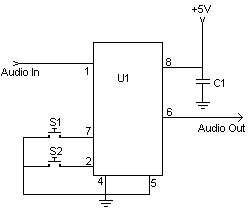

This digital volume control has no pot to wear out and introduces almost no noise in the circuit. Instead, the volume is controlled by pressing UP and DOWN buttons. This simple circuit would be a great touch to any home audio project.
Parts:
- C1 – 0.1uf Ceramic Disc Capacitor
- U1 – DS1669 Digital Pot IC (See Notes)
- S1, S2 – Momentary Push Button Switch
- MISC – Board, Wire, Socket For U1
Notes:
- U1 is available from Dallas Semiconductor.
- S1 turns the volume up, S2 turns it down.
- The input signal should not fall below -0.2 volts.
- Using a dual polarity power supply (+-5V works fine) will cure most clipping problems. You will have to check the datasheet for the correct pins to connect your voltages.

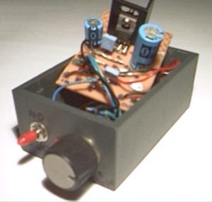
You can use this powerful amplifier in any small audio project. It is very small (6.5 x 4.5 cm) and it outputs 10W using a 9V battery.
Parts List
| Part | Value |
| R1 | 6Ω |
| R2 | 220Ω |
| R3 | nothing |
| R4 | 10 kΩ pontesiometer |
| C1 | 2200 uF / 25V |
| C2 | 470 uF / 16V |
| C3 | 470 nF / 63V |
| C4 | 100 nF |
| C5 | nothing |
| C6 | nothing |
| IC1 | TDA2003 |
TDA2003 Datasheet


