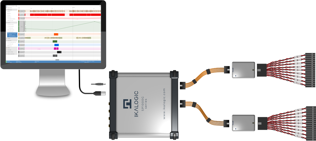
SP1000G series logic analyzers and arbitrary pattern generators, with a timing resolution of 1ns (1GSPS), can analyze logic signals and protocols in great detail. External reference clocking (IN and OUT), trigger input and output, and a threshold and output voltage level that can be adjusted making the SP1000G series a very powerful piece of lab equipment. SP1000G comes in three different versions with either 18, 36, or 54 channels. The SP1000G series was made so that each channel could be set up as an input, a push-pull output, or an open drain output.
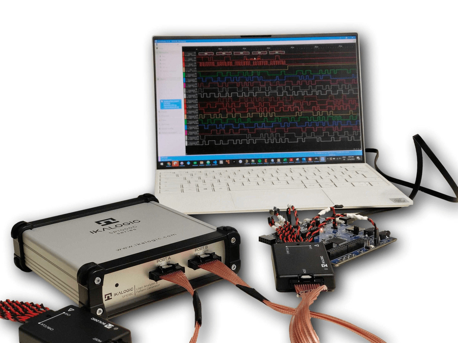
SP1000G series overview
There are three different logic analyzers in the SP1000G Series: the SP1018G, the SP1036G, and the SP1054G. They have between 18 and 54 channels. All SP1000G series logic analyzer devices provide equivalent features (like Sampling rate, trigger capabilities, and pattern generation).
SP1018G
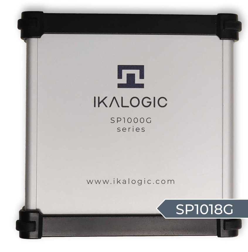 SP1018G 18 Channels Logic Analyzer pattern generator
- It has 18 channels for logic.
- Input, pushpull and open-drain configuratble channels are avaible.
- It can work in both timing mode and state mode up to 250MHz.
- Pattern generator that can be used on any number of channels.
- It has 18 channels and a sampling rate of 1 GHz.
- It works with voltages from 0.9 V to 5 V.
- It has 4 GB of buffer memory built in.
- There is a USB-3 interface for streaming.
SP1036G
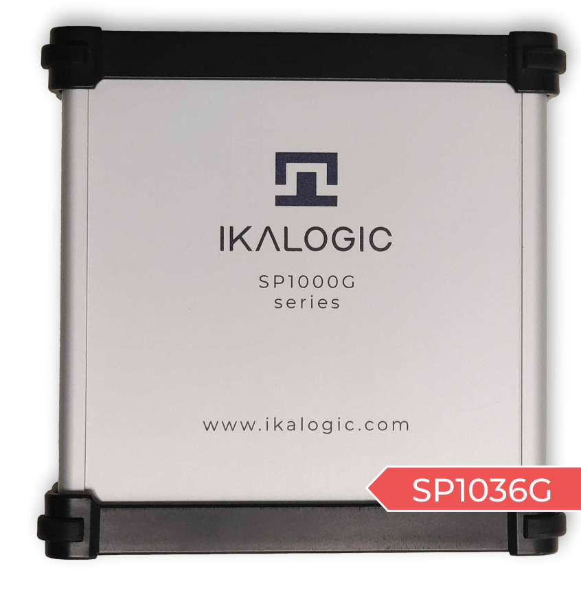
SP1018G 18 Channels Logic Analyzer pattern generator
- It has everything the SP1018G has.
- The logic board has 36 logic channels.
- It has 8 GB of buffer memory built in.
- One GSPS with 36 channels is included.
- It gives you a training session with just you.
SP1054G

SP1018G 54 Channels Logic Analyzer pattern generator
- It has everything the SP1018G has.
- 54 logic channels are included.
- It has 12 GB of buffer memory built in.
- It had one GSPS with 54 channels.
- It gives you a training session with just you.
- It meets the standards for the SP1000G Family.
Specifications for the SP1000G Family
It has a capture rate of 1 GSPS (adjustable down to 4 MSPS). It provides the highest possible sample rate when all channels are being utilized (no compromise between sampling rate and a number of channels). The Schmitt trigger input stages have thresholds that can be adjusted (each group of 9 channels can have a different input threshold), and additionally embedded buffer memory of about 4 Gb, 8 Gb or 12 Gb, depending on model, is present with super-speed connectivity using USB 3.
Samples compression (only events consume memory and USB bandwidth) is made possible. It comes with different trigger options like edge, pulse width, pattern, protocol and a sophisticated trigger pattern that can combine up to 18 channels from the same group can occur for example, Ports A & B or ports B & C. Furthermore, two separate trigger engines that can work in conjunction with one another to produce cascading trigger sequences is also made possible. It can generate a pattern at a rate of 250 MSPS pattern (maximum output frequency is 125MHz) and as one clock output that runs continuously for each set of 9 channels and one external sampling clock input (state mode), up to 250MHz, each group of 9 channels.
It provides protection against overvoltage on all of the inputs and outputs. On SMA ports, precise trigger-In and trigger-Out signals are available. Both the clock-in and clock-out rates for SMA ports are set to 10MHz. Active probe sets that are state of the art are able to provide precise timing measurement with very little capacitive loading. Thresholds that can be adjusted with a resolution of 1 mV for each active probe set (1 different threshold for each nine channels group) is made possible.
Signals collected by logic analyzers in the SP1000G series can be compressed and streamed to a computer running Windows, Linux, or Mac over USB 3. The maximum amount of data that can be transferred over a USB connection is typically a few hundred megabytes per second. However this limit can change from system to system. To get beyond the constraints imposed by USB, SP1000G logic analyzers come equipped with up to 12 GB of inbuilt DDR-3 memory. This memory buffers the collected samples.
It has strong options for triggers, which are listed below.
- Edge trigger.
- Change the logic on one or more channels.
- Triggers are based on a series of timed logic signals.
- Trigger when a protocol word or event happens (like serial word or I2C address acknowledgment)
- External trigger input.
- Trigger output.
- Two-stage trigger (Ex: Edge trigger, then, Trigger on I2C address).
Applications
SP1000G series logic analyzers and pattern generators are perfect for demanding applications that need to capture logic signals with a maximum time resolution of 1 ns on all channels. In fact, the SP1000G series lets you use the most channels possible without having to lower the sampling frequency (for example, SP1018 can capture signals on all 18 channels with 1ns resolution). The most common uses are:
- It can be used for automatic or manual evaluation of semiconductors.
- Helps in validation and testing of electronic circuits.
- Used for scientific research purpose.
- Fixing bugs in embedded systems.
- Aids in analysis of serial protocols, such as I2C, SPI, UART, or 1-Wire (non exhaustive list)
- Used for ADC diagnostic.
Benefits
It can record very long sequences of logic signals as a “live stream.” It can also build and generate logic patterns on the fly with the help of an easy-to-use scripting language that is based on JavaScript. Logic circuits can be tested automatically with this software.
Its software lets you look at decoded signals in different ways, like as packets or as detailed bits and bytes. The decoded signals are shown as a waveform, which makes it easier to analyse them (e.g., plot accelerometer data as a curve).
It also has a flexible multi-stage trigger system that lets it target very specific events. The device’s performance does not depend on the speed of the USB connection (Thanks to embedded memory).
Software works on Windows, macOS, and Linux, and it’s free, easy to use, and intuitive. Trigger IN and OUT ports let you sync samples you’ve taken with other lab instruments.

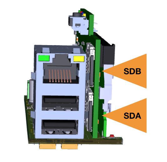 SD Card slots