Exploring Features of Fanless InuoMicro G4305L8-S2 Industrial PC Box

The InuoMicro G4305L8-S2 industrial PC box with eight 2.5GbE ports and a reasonably low cost is well suited for firewalls and other networking applications. It is powered by an Intel Celeron 4305U Whiskey Lake processor. The barebone computer offers interfaces like HDMI and DisplayPort video outputs and a few USB ports, allowing the user to use it as a standard computer. It also supports up to 32 GB RAM, one mSATA SSD, and one 2.5-inch SATA drive. Using mini PCIe and/or M.2 4G LTE and WiFi modules, wireless connectivity can be implemented.

Advantages

It secures your network with a small, silent, fanless firewall that is more powerful than a typical router. A greater range of terminals is supported. Support for Linux iptables, Windows pfSense, Sophos, VyOS, Linux, Untangle, etc. Apply to affordable options for small office home office (SOHO) internet access, home labs, virtual offices, SMBs, branch offices, and locations for remote workers.


Specification:

  • Products with an Intel Celeron Processor 4305U 2M Cache and 2.20 GHz Intel UHD Graphics for 8th Generation Intel Processors Whiskey Lake TDP 15 W.
  • Item dimensions 8.66 inches long, 5.04 inches wide, 1.85 inches high, and 4.4 pounds.
  • The operating temperature is between 0 and 50 degrees Celsius, and the non-operating temperature is between -20 and 80 degrees Celsius.
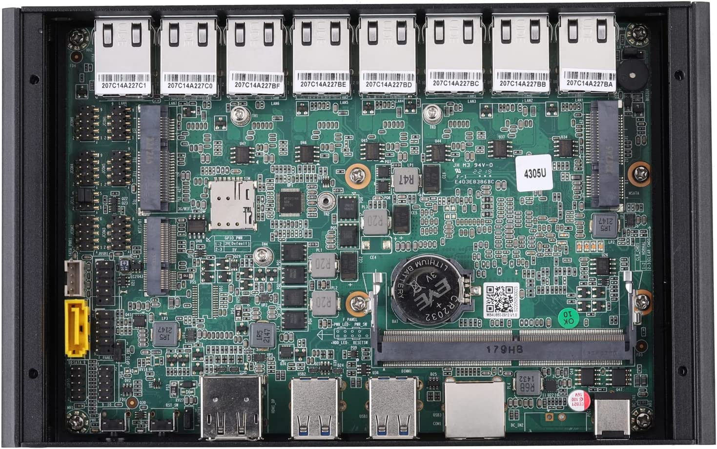
  • The hard drive can also hold one Mini-PCIe for mSATA SSD and one 2.5 “SATA SSD/HDD. (2.5 “Included is a SATA cable)
  • Memory up to 32 GB is supported by 1 x DDR4 SO-DIMM Socket, 2133/2400 MHz.
  • It has one full-length Mini PCIe for 4G and one half-length Mini PCIe for Wi-Fi only. Help USB Devices and M.2 Wi-Fi (E key, 2230)
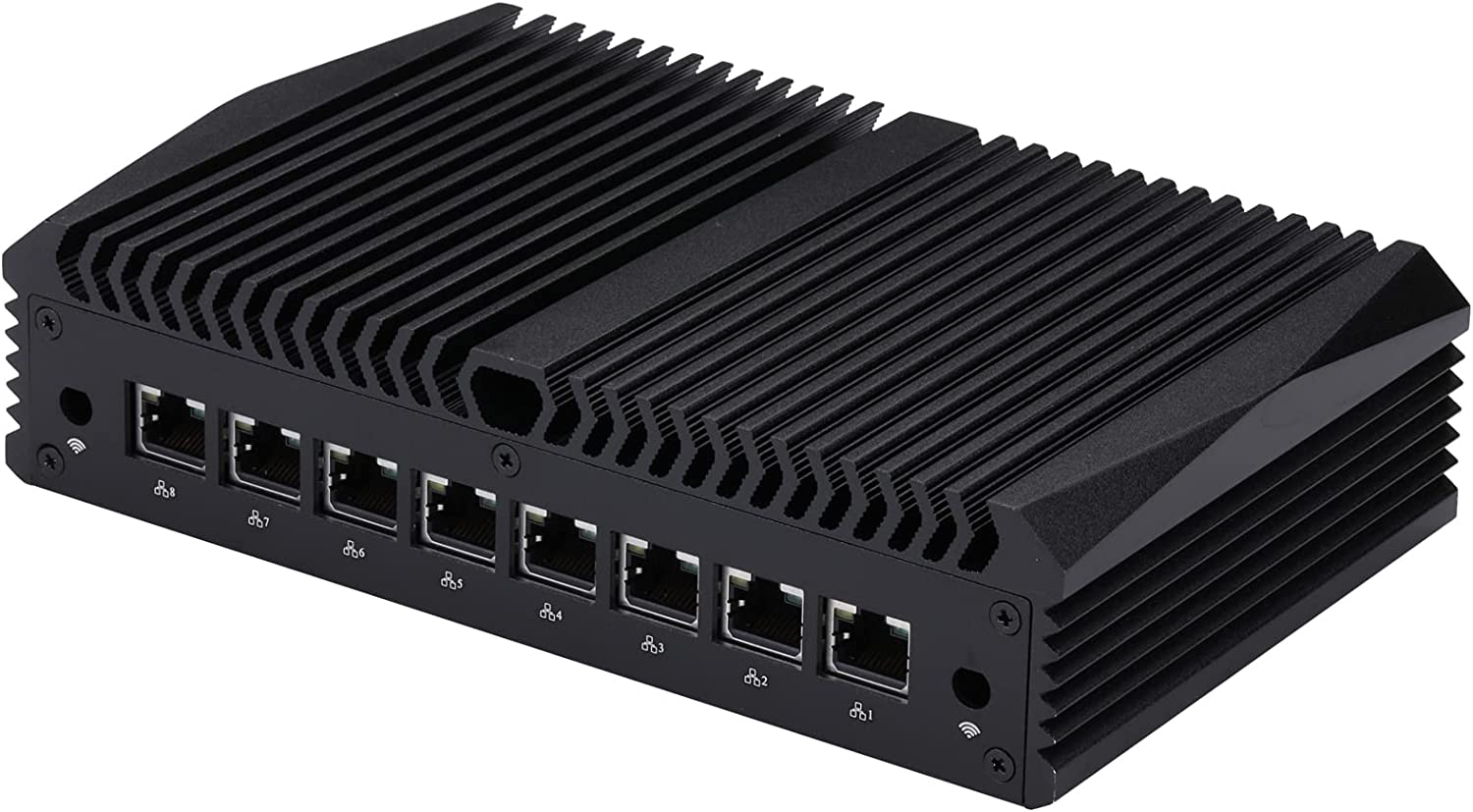
  • 8 Intel I225V 2.5G LANs are used for the local area network.
  • There is also one SIM card slot, one GPIO, one COMS Clear Jumper, and one Automatically Boot Jumper.
  • Item size is about 220 x 128 x 47 mm.
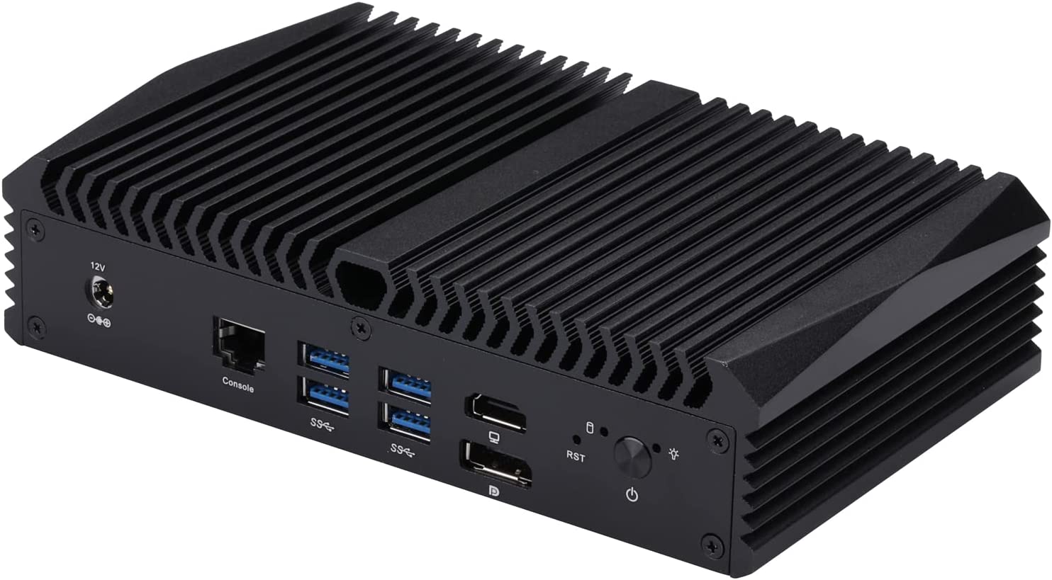
  • Front I/O has 1 x Power on/off Button, 1 x Reset Button, 4 x USB 3.0, 2 x USB 2.0, 1 x DC Jack, 1 x 2*3.5 mm Connector, 1 x HD Video, 1 x DP port.
  • There are 8 Intel I225V 2.5G LAN ports on the back I/O.
  • It can act as a host and can be used at home, the office, the library, the hospital, a restaurant, a bank, and almost any other place where a computer is needed.
  • Windows 10, Linux, Ubuntu, Pfsense, CentOS, and Untangle are all supported operating systems. The Intel Celeron 4305U is on the list of processors supported by Microsoft’s most recent operating system, but Windows 11 is not.

On Amazon, InuoMicro is offering the G4305L8-S2 box PC for a price of $203, and if it was simply an OEM model that would soon be sold under different brands, it would not be a surprise.

Texas Instruments TPS25961 100miliΩ eFuse

Texas Instruments TPS25961 100mΩ eFuse is an integrated FET hot-swap device combined to create a highly integrated circuit protection and power management solution. The TPS25961 features multiple protection modes using very few external components and is a robust defense against overloads, short circuits, voltage surges, and excessive inrush current.

The TI TPS25961 output current limit level is set with a single external resistor. Meanwhile, the inrush current is managed using output slew rate control internally. The eFuse has an option to externally set a user-defined overvoltage cutoff threshold or use a fixed internal threshold. This option protects an input overvoltage condition.

The TPS25961 is characterized for operation over a junction temperature range of –40°C to +125°C and is available in a small, 2mm x 2mm SON package.

Features

  • 2.7V to 19V Wide input voltage range
    • 21V absolute maximum
  • Overvoltage protection with a response time of 1.3μs (typical)
    • 5.98V (typical) Fixed internal threshold
    • Adjustable threshold using an external resistor divider
  • Overcurrent protection:
    • 0.1A to 2A Adjustable current limit threshold
    • Current limit accuracy:
      • ±20% (typical) across the current range
      • ±18% (maximum) at 1.45A current limit, TA = 25°C
  • Low on-resistance Ron = 106mΩ (typical)
  • Active high enable input with adjustable undervoltage lockout (UVLO)
  • Short-circuit protection with a response time of 5μs (typical)
  • 5.17V/ms (typical) Output slew rate control (dVdt)
  • Overtemperature protection (OTP)
  • Auto-retry after fault
  • 130μA (typical) Low quiescent current
  • UL 2367 recognition (pending)
  • IEC 62368 CB certification (pending)
  • Small footprint of 2mm x 2mm SON package

Application Schematic

High-performance, Inductor Built-in Step-up “micro DC/DC” Converter XCL104/XCL105 Series

Torex Semiconductor Ltd. has launched a high-performance, 1.4A inductor built-in step-up “micro DC/DC” Converter— XCL104/XCL105 series.

The XCL104/XCL105 series is a synchronous step-up “micro DC/DC” converter with a built-in 1.4A driver and a built-in coil that is suitable for various uses. Since the coil is integrated, it helps to reduce the size of the product as well as the time consumed for selecting the components because of fewer external component counts. As a result, the development work period can be greatly shortened. In addition, since the coil pattern is the shortest on the board layout, low noise is achieved.

The series is able to start operation from an input voltage of 0.9V, suitable for equipment using a single Alkaline battery or Nickel metal hydride battery. The output voltage range is 1.8V to 5.5V and can be set in 0.1V increments. Compared to conventional products, this product achieves 1.4 times the output current compared to previous products. In addition, the product can choose 3 functions, further reducing the power consumption of IC-equipped devices and extending battery life.

The Load disconnect type is equipped with load disconnection and CL discharge functions to reduce the output voltage at high speed to prevent the output device from malfunctioning in standby mode.

The bypass type corresponds to a large range of working voltages such as MCU. When the MCU is in sleep, input and output are conducted by the bypass function, the battery voltage is supplied as it is. Boosting only when a constant voltage such as 3.3V is required will greatly help reduce overall power consumption.

The output OR types are ideal for output connection (OR connection) of multiple power supplies and backups. The load disconnection function cuts off the continuity between the input and output and makes an OR connection to the output with other power supplies. In addition, it supports automatic switching with other power supplies connected by OR.

In addition, the UVLO function (option: 1.46V) can stop IC operation when the battery voltage is too low, which can reduce the leakage of alkaline batteries.

The operating temperature range is up to +105°C, making it ideal for industrial equipment that requires small size, low power consumption, multi-functions, and high performance, IoT, mobile, wearable, and all equipment that emphasizes battery life.

Torex will continue to swiftly develop products that meet market needs and contribute to a richer and more abundant society.

more information: https://www.torexsemi.com/products/built-in-dcdc-converters/series/?name=xcl104

Espressif Systems ESP32­-S3-­MINI Module

Espressif Systems ESP32-­S3­-MINI Module is a powerful, generic Wi-Fi® + Bluetooth® LE MCU module that features a rich set of peripherals. This module offers 2.4GHz Wi-Fi® (802.11 b/g/n) and Bluetooth® 5 (LE) built around the ESP32-S3 series. The ESP32-S3­-MINI module features SoCs, Xtensa® dual­ core 32­bit LX7 microprocessor, flash up to 8MB, and optional 2MB PSRAM in a chip package. This module operates at a -40ºC to 105°C ambient temperature range for the 105°C version and -40ºC to 85°C for the 85°C version. This module is ideally used in embedded systems, smart homes, and wearable electronics.

Features

  • CPU and On-­Chip memory:
    • 384KB ROM
    • 512KB SRAM
    • 16KB SRAM in RTC
    • Up to 8MB Quad SPI flash
    • 2MB PSRAM (ESP32-S3FH4R2 only)
  • Wi-­Fi:
    • 802.11 b/g/n
    • 802.11n up to 150Mbps bit rate
    • 0.4µs guard interval support
    • 2412MHz to 2484MHz center frequency range
  • Bluetooth:
    • Advertising extensions
    • Multiple advertisement sets
    • 125Kbps, 500Kbps, 1Mbps, and 2Mbps speed
  • Peripherals
  • Antenna options:
    • On-board PCB antenna (ESP32-S3-MINI-1)
    • External antenna via a connector (ESP32-S3-MINI-1U)

more information: https://www.espressif.com/sites/default/files/documentation/esp32-s3-mini-1_mini-1u_datasheet_en.pdf

Espressif Systems ESP32-C6-WROOM-1 Multiprotocol Modules

Espressif Systems ESP32-C6-WROOM-1 Multiprotocol Modules are general-purpose Wi-Fi®, IEEE 802.15.4, and Bluetooth® LE modules. These multiprotocol modules are built around the ESP32-C6 series of SoCs and 32-bit RISC-V single-core microprocessors featuring 4MB flash. The ESP32-C6-WROOM-1 multiprotocol modules feature 23 GPIOs, rich peripherals, and an onboard PCB antenna. These multiprotocol modules integrate a rich set of peripherals, including SPI, parallel IO interface, controller, and on-chip debugs functionality via JTAG and SOC event task matrix.

The ESP32-C6-WROOM-1 multiprotocol modules feature CPU and on-chip memory, Wi­Fi, integrated components on the module, and Bluetooth. These multiprotocol modules operate at a 3V to 3.6V operating voltage range. The ESP32-C6-WROOM-1 multiprotocol modules are ideally used in smart homes, industrial automation, health care, and consumer electronics applications.

Features

  • Wi-Fi:
    • IEEE 802.11ax-compliant:
      • Beamformee that improves signal quality
      • Channel Quality Indication (CQI)
      • Dual Carrier Modulation (DCM) to improve link robustness
      • Spatial reuse to maximize parallel transmissions
      • Target Wake Time (TWT) that optimizes power-saving mechanisms
    • Fully compatible with IEEE 802.11b/g/n protocol:
      • Data rate up to 150Mbps
      • Wi-Fi Multimedia (WMM)
      • Immediate block ACK
      • Fragmentation and defragmentation
      • Transmit Opportunity (TXOP)
      • Automatic Beacon Monitoring (Hardware TSF)
    • 2412MHz to 2484MHz operating frequency range
  • Bluetooth®:
    • Multiple advertisement sets
    • Advertising extensions
    • High power mode (share the same PA with Wi-Fi)
  • Peripherals
  • Antennal options:
    • On-board PCB antenna
  • CPU and On-Chip memory:
    • ESP32-C6 embedded, 32-bit RISC-V single-core microprocessor, up to 160MHz
    • 320KB ROM
    • 512KB SRAM
    • 16KB Low-power (LP) SRAM

more information: https://www.espressif.com/en/products/socs/esp32-c6

Smart Wi-Fi Scale Geared Up With ESP32

A wide range of uses is possible for low-cost kitchen scales. They are typically quite basic devices without features like wireless connectivity. Still, Liore Shai made the decision to change that by adding Wi-Fi functionality to an Amazon Basics scale which cost about just $10 shipped at the time of purchase using an ESP32 board.

The hack’s basic idea is simple: use the load cell and mechanical parts that already exist, then send data to an ESP32 for wireless distribution. A load cell is a tool that changes a certain kind of force into an electrical signal that can be accurately read and applied to various tasks. A load cell emits a tiny voltage signal in the microvolt range, which is largely useless to standard microcontrollers. This is the trick in this situation.

In order to obtain a reliable reading from the load cell for proper voltage measurement, Shai added an HX711 load cell amplifier. This module transmits data to the ESP32 using a protocol akin to I2C, allowing it to get a stable, accurate reading from the load cell. This data is then used by the ESP32 to create a local web server. A pair of buttons are used for setup, and a 128×32 pixel OLED screen is used for local user feedback.

Shai demonstrates that first, the load cell must be soldered to the HX711 module; then, it must be connected to the ESP32 board. HX711 was hot-glued to the ESP32 board’s back. The physical setup may vary depending on the microcontroller. The OLED screen connections and the two buttons are connected after the HX711 VCC, GND, data, and clock pins are connected to the ESP32. The process of programming the smart scale starts once all connections have been soldered and tested by flashing the microcontroller over USB!

On GitHub, Arduino-style code is accessible, and this Reddit post includes a video of the scale actually weighing objects. Shai suggests that this range from monitoring 3D printer filament levels to pairing with Home Assistant to be aware of when you need to restock items like coffee, sugar, salt, and more. Of course, a variety of hardware could be used to implement this Wi-Fi add-on concept, so the posted code and configuration may only be a starting point!

Smart plug ESP32 OpenMQTTGateway serving as an BLE MQTT gateway and a Power meter

In order to function as a BLE MQ Telemetry Transport (MQTT) gateway and power meter compatible with Home Assistant, Homebridge, OpenHAB, DomoticZ, FHEM, Jeedom, NodeRed, AWS, and any MQTT-compatible IoT or Smart Home system, the Theengs Plug ESP32 smart plug runs OpenMQTTGateway firmware.

Theengs open-source tools

Even though the Matter standard should make it easier for Smart Home frameworks to work together over time, there are still millions of devices on the market that don’t work with Matter. The Theengs Plug aims to at least partially solve this problem by helping users reduce the number of hubs they need and have only one that works with different ecosystems.

Theengs Plug hardware features a dual-core ESP32 wireless MCU with 2.4 GHz WiFi and Bluetooth LE connectivity. It has a number of other specifications. With a power supply of 100-120  VAC, 60Hz, and up to 15 A, MQ Telemetry Transport makes up the network protocol. The device has dimensions of 103 x 61 x 34.6mm and a storage temperature range of roughly -10 °C to 50 °C. Its operating temperature range is 0 °C to 40 °C. 0 % to 95 % relative humidity (no condensation) with UL certification.

A few applications for the Theengs Plug and other ESP32 board loads with OpenMQTTGateway, along with a suitable BLE sensor and an MQTT broker, include plant monitoring, temperature and humidity monitoring for cigar boxes, refrigerators, rooms, and cooking (BBQ), the measurement of CO2, particle matter, and formaldehyde levels in your home, monitoring water and energy usage when taking a shower, and more.

The OpenMQTTGateway firmware supports more than 70 sensors, and as we’ve previously mentioned, Theengs offers a variety of open-source BLE tools to go with the firmware. The creator lists some additional advantages as well, including support for the Home Assistant auto discovery convention, OTA updates, low power mode, SSL support, and more. Additionally, you’ll discover some documentation for the Theengs Plug.

Although you can install the Python-based Theengs Gateway on a Raspberry Pi SBC or flash OpenMQTTGateway on additional ESP32, ESP8266, or Arduino boards, buying the Theengs Plug will be more convenient and will also help the project. The OpenMQTTGateway smart plug is currently available in the US for $39.90, but it will also be made in Europe, according to plans for support in other regions.

An affordable SDI signal generator using Arduino MKR Vidor 4000

Transmission of video from one location to another in the professional video world is typically done via SDI (Serial Digital Interface). This FPGA-powered device, intended as a test tool for SDI circuits, pushes signals at 1.485 Gbps. Based on an Arduino MKR Vidor 4000, Chris Brown of the sports media technology company Tempus Ex has created “possibly the world’s cheapest SDI signal generator.”

“In the world of professional video, SDI (Serial Digital Interface) is the industry standard for getting video from point A to point B,” Brown provides context before explaining.

“It’s the professional’s equivalent of HDMI for consumer electronics. At any large-scale, televised event, you can bet that somewhere behind the scenes, there’s a rat’s nest where all of the videos come together and are distributed via SDI.”

The carrier board for Chris Brown’s Arduino MKR Vidor 4000 Carrier Is “Possibly the World’s Cheapest SDI Signal Generator.”

The cost of SDI hardware tends to be higher than one might expect for something designed for professionals, but Brown notes that while the standard can support high bitrates, SDI is actually quite straightforward. He created a low-cost SDI signal generator, which he refers to as “the ‘hello world'” of SDI hardware, to demonstrate his point.

“To keep it simple, we’ll just make the signal some flashing colors. And we’ll aim to make this a 1080p30 signal, which can be transmitted via HD-SDI,” Brown composes. “In theory, we just need to program a microcontroller that can send a 1.485 Gbps signal to a cable driver. This would work if we could get our hands on such a microcontroller, but 1.485 Gbps is quite fast. To be able to generate a signal at that speed, we’ll need an FPGA, which can be programmed using a lower-level hardware description language to perform much faster operations.”

The Arduino MKR Vidor 4000 has both a microcontroller and an Intel Cyclone 10 FPGA, which is exactly what is required for the project. Although its performance falls short of the level required for nearly 1.5 Gbps of data throughput, a Semtech GS2962 serializer completes the build; ten data lines, each delivering 148.5 Mbps, are run in parallel to achieve the required level of performance.

To achieve the desired level of performance, the Arduino MKR Vidor 4000 employs Cyclone 10 FPGA. (Source: Chris Brown)

“As far as I know,” Brown writes,

“this is the first time an Arduino has been capable of generating and emitting arbitrary SDI video signals, and as far as I know, this is also the cheapest SDI signal generator available anywhere. SDI signal generators typically cost anywhere from $350 to $2,000. This one costs ~$87 for the Arduino and ~$95 for the transmitter parts and assembly at low volumes. Although I don’t recommend using an Arduino like this in mission-critical workflows, it can be a valuable tool in the lab.”

The complete article by Brown is available on the Tempus Ex blog, while the design files and source code are available on GitHub under an open-source license that is not specified.

Translating “Dah” and “Dit” Speech Into Morse Code with an CWVox using Arduino

image: CWvox Prototype connected to the radio (Source: Kevin Loughin)

These days, it seems like every speech-detection-related project is based on some kind of advanced algorithm, such as machine learning, pattern matching, or spectrum analysis. But Kevin Loughin (AKA KB9RLW), an amateur radio operator, built CWvox, a voice-activated keyer that uses the analog-to-digital converter (ADC) on an Arduino Nano to translate spoken dits and dahs into morse code. Morse code, also known as “CW,” is a system of secret symbols (or words) based on alternating short and long tones. To represent the short burst in writing, a dot is used, while the long burst is represented by a dash.

Most people’s mental image of Morse code involves the short and long tones produced by a device called a keyer. The majority of these gadgets feature paddles that are activated with the user’s thumbs and forefingers. So, what do you do if you lose the ability to use your fingers and thus a keyer? CWvox is necessary due to this snag.

Those who work with radios will recognize these tones as “Dit” (short) and “Dah” (long) in Morse code. It turns out that there is a tiny difference in the amount of time it takes to say each of these words, and that difference is enough for effective and straightforward word detection. At least when your focus is limited to a single phrase!

CWvox Schematic (Source: kb9rlw.blogspot.com)

The heart of CWvox is an Arduino Nano. The Nano microcontroller is a basic eight-bit design without DSP capabilities. To translate verbal morse code into electronic tones, you only need that board, a few transistors, and a few passive parts. For the Nano’s positive-only ADC, the discrete parts on the input side amplify, bias, and filter the signal. A BJT buffers the signal on the output side before it enters the radio’s keying input.

The CWvox voice-operated keyer for versal morse code (Source: Kevin Loughin, Youtube)

In the above video, at 09:45, KB9RLW gives a live demonstration of CWvox in use. And it’s amazing to watch and listen to! To view a detailed explanation of the overall circuit, fast forward to 13:15 in the same video.

The complete CWvox article is available here. For the Arduino Nano code, you can also look at this GitHub repository. You should also look at the code to see how elegantly straightforward this design is!

Radxa’s Rock 5A, Rivals the Raspberry Pi 4

Radxa has unveiled the Rock 5A, a Raspberry Pi alternative that looks very similar to the Raspberry Pi 4, but with the added benefit of 8K video support and up to 16GB RAM. The new Rock 5A is not so different from the Raspberry Pi 4 Model B. It is roughly the same size as a Raspberry Pi 4 Model B, but with higher performance.

The Rock 5A is an attractive option compared to the Raspberry Pi due to its price and performance. For only $99, you can pre-order the 4GB model, which has enough RAM for most single-board computer users. Retro gamers will likely pick this model as it has enough RAM to emulate classic games, including some from the PlayStation 2 era, which is now considered retro.

Rock 5A backside

The Rockchip RK3588S system-on-chip (SoC) is the foundation of the new board, featuring four Arm Cortex-A76 cores running at 2.2-2.4GHz and four lower-power Cortex-A55 cores running at 1.8GHz. Additionally, it has an ARm Mali G610 MC4 graphics processor with OpenGL ES 3.2, OpenCL 2.2, and Vulkan 1.2 support, a neural processing unit (NPU) accelerator with a claimed to compute performance of 6 trillion operations per second (TOPS) at INT4 precision, and a selection of 4GB, 8GB, or 16GB of LPDDR4x memory modules.

The Rock 5A features two micro-HDMI video outputs. One of the outputs supports 8k60 and the other 4k60 output, as well as a four-lane MIPI Display Serial Interface (DSI) connector, all of which can be used simultaneously. It also enables hardware video decoding of H.265/H.264/AV1/AVS2 at up to 8k60, a single physical MIPI Camera Serial Interface (CSI) that can function as one four-lane or two two-lane ports, an eMMC connector, and an M.2 E-key slot for high-speed storage, a microSD slot, two USB 2.0 ports, two USB 3.0 ports (one of which can act as a USB On-The-Go (OTG) port), and a gigabit Ethernet port.

No wireless networking is available on the board however, it can be added with a USB dongle or an M.2 card. It does offer a real-time clock with optional battery backup, a user-controllable status LED, a fan connector with pulse-width modulated (PWM) speed control, and a 40-pin general-purpose input/output (GPIO) header with a range of signals including one CAN bus, up to three SPI and six I2C buses, two SPDIF and one PCM/I2S signals, up to five UARTs of which two have hardware flow control, seven PWM pins, one analog input, and two each of 5V and 3.3V power pins.

Radxa has announced that the board will be available for purchase at the end of Q1 2023, with the 4GB model priced at $99, the 8GB model at $119, and the 16GB model at $159. However, through a partnership with ALLNET China, pre-order codes can be purchased for $5, which will provide a $30 discount, reducing the prices to $74, $94, and $134 respectively. For more information, visit the Radxa forum page.

TOP PCB Companies