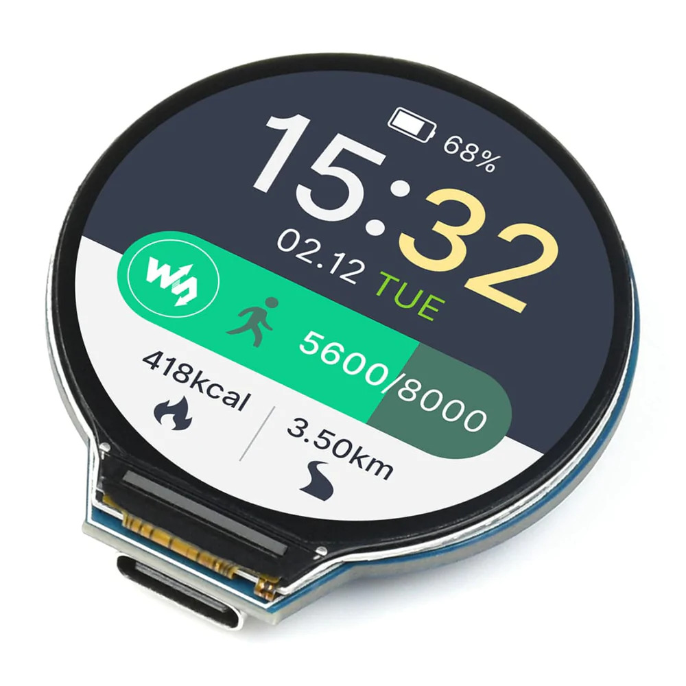
Waveshare developed the RP2040-LCD-1.28, which is an MCU board that combines a good price with a nice performance. The fact that it has a 1.28-inch LCD round display, a Li-ion battery charger, a 6-axis sensor (3-axis accelerometer and 3-axis gyroscope), and so on, in addition to adapting all GPIO and Debug headers, enables you to develop and integrate it into products quickly and easily despite its diminutive size. The Waveshare RP2040 uses the RP2040 microcontroller, as its name suggests.
Raspberry Pi RP2040 has two Arm Cortex M0+ processors (up to 133MHz), 264kB of SRAM, and 2MB of Flash memory on the chip. The built-in display is a GC9A01A, which is a 1.28-inch IPS LCD display that can talk over SPI. The IMU (QMI8658C) has a 3-axis gyroscope and a 3-axis accelerometer that work together. Both of these sensors have a resolution of 16 bits. The 1.27-pitch female headers can be used to get to the GPIOs. But the product page says that some of these pins “are multiplexed to the internal circuit.” There are 2x SPI, 2x I2C, 2x UART, 4x 12-bit ADC, and 16x PWM channels that can be used for communication. The board also seems to have an MX1.25 header for a rechargeable and dischargeable 3.7V lithium battery.
RP2040 MCU chip was designed by Raspberry Pi in the United Kingdom. It contains a Temperature sensor, accurate clock and timer on-board, accelerated floating-point libraries on-chip, and 8 x Programmable I/O (PIO) state machines for providing support for bespoke peripherals.
NOR-Flash memory of 2 megabytes is also included. The screen has a resolution of 240×240 pixels and measures 1.28 inches diagonally. I/O Interfaces has roughly 30 GPIO muxed pins (with female headers), 1x IMU (3-axis gyroscope and 3-axis accelerometer), and 1x Temperature sensor. There is one USB Type-C connection. Additional features include a button labeled 1x Reset as well as a button labeled 1x Boot. The power comes from a single Lithium battery that has a connector for both charging and discharging.
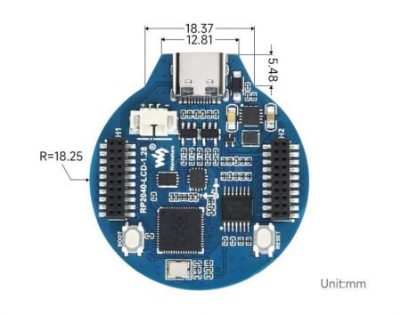
Here is where you can find the Wiki page for this product. On GitHub, you can also find a clock demo project made by Daniel Wienzek. The Waveshare RP2040 board can be bought on ThePihHut.com for £17 (about $18.13).
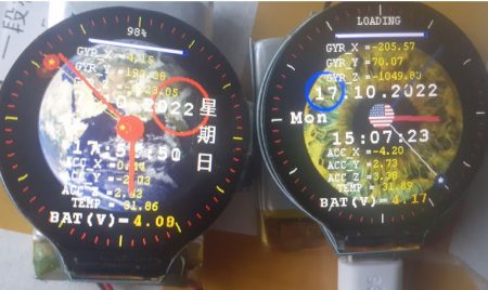
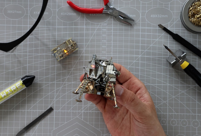
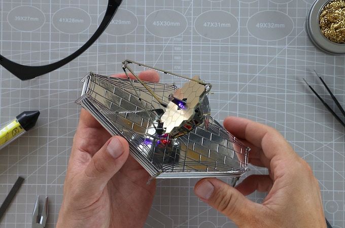
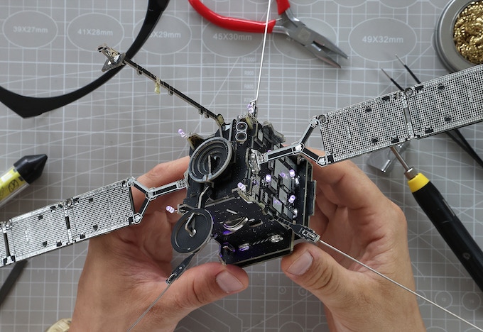
A Geek Club is a group of designers and engineers who make electronic construction kits for people in over 70 countries around the world who are interested in learning more. Their engineering and robotics kits are made to stretch your mind, improve your skills, and help you learn more about electronics and space. They made a set of 5 very detailed electronic building kits that were inspired by NASA and other space agencies around the world. Choose from the International Space Station, the Apollo Lunar Module with Moon Rover, the James Webb Space Telescope, the Solar Orbiter, or the CubeSat NEA Scout. Each kit comes with PCB parts that are already made, an instruction manual, an educational book about circuitry, and a lot of parts (plus extras, just in case!)
The International Space Station (ISS) was built in 1998 by experts from 15 countries. It is a huge project. It’s a sign of unity and new ideas. The biggest thing ever made by Geek Club. It has solar panels that will actually power it, a flexible PCB, a DIY model stand with a wire for hanging the display, and solar panels that will actually power it. The size is 21.7 by 10.8 by 14.2 inches (550 x 275 x 360 mm). It was made by NASA (United States), Roscosmos (Russia), ESA (Europe), CSA (Canada), and JAXA (Japan).
In 1969, the Apollo 11 Lunar Module Eagle (LM) and Moon Rover (LRV) were built. They are a historic and well-known spacecraft that took us to the moon for the first time. It comes with a Moon Rover that you can put together and drive. Apollo is about 3.9 by 3.9 by 2.9 inches (96x99x75). Moon Rover is about 1.9 by 1.1 by 1.3 inches (48x27x32). NASA came up with it (United States)
The James Webb Space Telescope (2022) is the next generation of space telescopes. It will be almost a hundred times more powerful than The Hubble. It will tell us where the universe came from and take us to the edge of what we know. It has a PCB that is covered in gold. The size is 7.1 by 4.9 by 3.9 inches (180x125x100mm). It was made by NASA (United States), ESA (Europe), and CSA (Canada)
Solar Orbiter, built in 2020, is a super-heat-resistant Sun-observing satellite that will let us look around the sun closer than ever before. It even has solar panels that will power it! It comes with a DIY model stand that has a wire display hanging from it. The size is 18.7 by 14.2 by 6.8 inches (475X360X175mm). It was made by ESA (Europe) and NASA (United States)
After the Artemis I Launch, NASA made a solar sail for the Cubesat Near-Earth Asteroid Scout to explore a small asteroid. The spacecraft NEA Scout will study an asteroid that is about the size of a school bus. This is the smallest asteroid that has ever been studied by a spacecraft. This mission will help us keep other asteroids from hitting our planet. It has a gold-plated PCB, solar panels to power it, and a ceiling wire to hang it from the ceiling. Size is 17.7 by 17.7 by 6.1 inches (450x450x155mm). The NASA’s Marshall Space Flight Center is in Huntsville, Alabama, and NASA’s Jet Propulsion Laboratory is in Pasadena.
The Space Kit has a soldering iron, a soldering iron stand, solder wire, a filing tool, tweezers, pliers, a soldering iron cleaner, protective glasses, a magnifying lens, PCB panels with dozens or even hundreds of parts, a flexible PCB, solar panels, and SMD LEDs. The parts of different models differ.
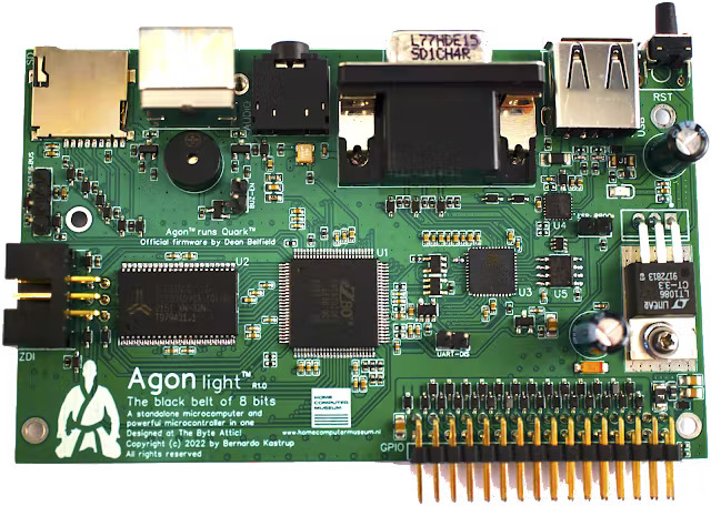
European computer company Olimex Ltd. has created Agon light a budget-friendly microcomputer and microcontroller on one small board. Bernardo Kastrup designed the AgonLight and the Quark firmware was developed by Dean Belfield. The module is the cheapest and fastest 8-bit microcomputer ever made as per the claims by Olimex Ltd. Agon Light isn’t a microcontroller development board like an Arduino nor a conventional single-board computer like a Raspberry Pi, but rather something in-between the two. It is designed using KiCad instead of EasyEDA.
This project is open-source hardware and software. Agon light can also be seen as an embedded basic computer as it has plenty of GPIOs that allow users to interact with components and modules.
Hardware Specifications of Agon Light
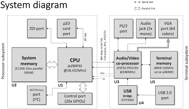
The CPU of the module are ZILOG’s eZ80F92 which runs at 18.432 Mhz clock speed. The unit has 128KB on-chip flash program memory and an extra 256-byte configuration flash memory.
The system memory is 512KB of SRAM. 8MB of PSRAM is dedicated to audio/video memory.
Also, the CPU is packed with 8KB SRAM and has 24-Bit GPIO. 2 universal asynchronous receiver-transmitter(UART) are also available on the CPU.
Agon light uses the Espressif ESP32-PICO-D4module as a VDP (video display processor) which operates at 240MHz. The ESP32-PICO-D4 also handles audio output.
The module contains a PS/2 keyboard port and a MicroSD card slot for storage.
Connectivity Features of the Module
Agon light has a VGA port for video output with 640×480 resolution and 64 simultaneous colors. The power is delivered by a USB-C connector which is a good choice as all new phones, tablets, and other devices use USB-C for charging and data transfer. The board is built for maximum flexibility, which means there are lots of options to do a single task. Instead of having to program kernel code in assembly to write to EPROM, its entire firmware can be programmed in C language. It can be done with freely-available tools such as Arduino IDE and Zilog’s ZDS-II IDE.
Agon light is an 8-bit microcomputer that boots into a basic programming interpreter. This device is for users who are into retrocomputing. It’s like old-school ZX spectrum or Commodore 64 computers but with much more capabilities. Due to modern hardware and interfaces, the possibilities of the module have increased drastically. In the past when cartridges were used to store games the Agon light used microSD which is much faster and more massive in storage capabilities. It is not just a modern version of old 8-but computers. The amazing connectivity features enable the module to interact with various other devices.
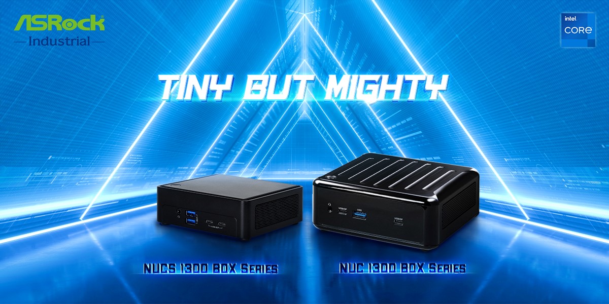
Introducing the new leading-edge products of unparalleled power and performance, ASRock Industrial launches the mighty trio- NUC 1300/D5 BOX, NUC 1300/D4 BOX, and NUCS 1300/D4 BOX Series enabled by 13th Gen Intel® Core™ Processors (Raptor Lake-P). Featuring performance hybrid architecture supporting up to 12 cores (4P+8E) with Intel® Iris® Xe Graphics, the NUC 1300/D5 BOX Series leverage the first DDR5-4800 MHz memory up to 64GB while bringing mighty capabilities with one USB4 support, four USB 3.2 Gen2, up to 4K quad displays, 2.5G dual LAN, Wi-Fi 6E, and dual storages. Meanwhile, the new slim-type NUCS 1300/D4 BOX Series come with 4K quad displays, one USB4, five USB 3.2 Gen2, and one 2.5G LAN along with WiFi 6E. The tailored features ensure a wide range of upgraded applications in gaming, content creation, productivity, business, AI BOX, smart retail, and more.
Brand-new NUCS 1300/D4 BOX Series for Slim Type Mini PC
The NUCS 1300/D4 BOX Series- NUCS BOX-1360P/D4 and NUCS BOX-1340P/D4 are one mighty package powered by 13th Gen Intel® Core™ i7/i5 Processors (Raptor Lake-P), particularly for slim type systems. The series feature two SO-DIMM DDR4-3200 MHz up to 64GB, with up to 4K quad-display through two HDMI 2.0b, two DP1.4a (from Type C) for lifelike visual experience, plus one 2.5G LAN and WiFi 6E for reliable connections. For rich IOs and expansions, there are one USB4, five USB 3.2 Gen2 (Type C and A), and one M.2 Key M (2242/2280) for storage. Moreover, a 12~19V DC-in jack design with TPM 2.0 onboard is also equipped. The NUCS 1300/D4 BOX Series follow suit in its mighty capabilities, with an even tinier size of 110.0 x 117.5 x 38mm fanned barebone, bringing next-level potentials in retail solutions such as digital signage, kiosk, POS, as well as enhanced gaming experience and office boost on PCs.
Tiny but Mighty- NUC 1300/D5 BOX Series and NUC 1300/D4 BOX Series
The NUC 1300/D5 BOX Series- NUC BOX-1360P/D5, NUC BOX-1340P/D5 powered by 13th Gen Intel® Core™ i7/i5 Processors (Raptor Lake-P) integrate performance hybrid architecture of 4 P-cores and 8 E-cores. The NUC 1300/D5 BOX Series feature the first dual channel DDR5-4800 MHz SO-DIMM memory up to 64GB for mighty multitasking abilities. You can also enjoy up to 4K quad displays through one HDMI 2.0b, one DP 2.1 (from USB4), and two DP 1.4a (one from Type C) with Intel® Iris® Xe Graphics, providing clear and vivid visions. Moreover, rich IOs connectivity supports 2.5G dual-LAN and WiFi-6E along with one USB4 and four USB 3.2 Gen2 ports. There are also dual storages of one M.2 Key M (2242/2260/2280) and one SATA 3.0 to optimize overall capacity. Optimal power and performance are carried in a compact shell of 110.0 x 117.5 x 47.85mm (W x D x H) with fanned barebone, giving its tiny but mighty reputation. Moreover, there is a 19V/90W power adapter and a 12-19V DC-in jack designed for flexibility under inconsistent power input plus TPM 2.0 onboard for hardware-based security.
The NUC 1300/D4 BOX Series- NUC BOX-1360P/D4, NUC BOX-1340P/D4, also powered by 13th Gen Intel® Core™ i7/i5 Processors (Raptor Lake-P) feature dual-channel DDR4 3200 MHz SO-DIMM memory up to 64GB, and quad-display through one HDMI 2.0b, and three DP 1.4a over two type C for maximum resolution up to 4K. For rich IOs and expansions, the series provide one USB4, four USB 3.2 Gen 2, two Intel 2.5G LAN, one M.2 Key E (Wifi-6E) for high-speed connectivity plus dual storages support with one M.2 Key M (2242/2260/2280) and SATA 3.0 that allows mighty performance in the compact fanned barebone that is the same size as NUC 1300/D5 BOX Series. The NUC 1300/D4 BOX Series have a 12-19V DC-in jack design with a 19V/90W power adaptor and TPM 2.0 onboard for enhanced security.
The NUC 1300/D5 BOX, NUC 1300/D4 BOX, and NUCS 1300/D4 BOX Series activated by 13th Gen Intel® Core™ Processors (Raptor Lake-P) are the mighty choices for you. “With the industry-leading features of 13th Gen Intel® Core™ Processors (Raptor Lake-P), particularly the first DDR5 support that ensures faster performance, higher memory bandwidth, and better power efficiency covered in a smaller dimension,” said James Lee, President of ASRock Industrial. “ASRock Industrial’s NUC 1300 BOX/ NUCS 1300 BOX Series are expected to effectively integrate these features to reach new heights in ranged applications while leading in time-to-market as one of the first 13th Gen Intel® CPU Powered Mini PCs.”
To learn more about ASRock Industrial’s NUC 1300/D5 BOX, NUC 1300/D4 BOX, and NUCS 1300/D4 BOX Series, feel free to visit our Website Product Page or contact us via Product Inquiry.
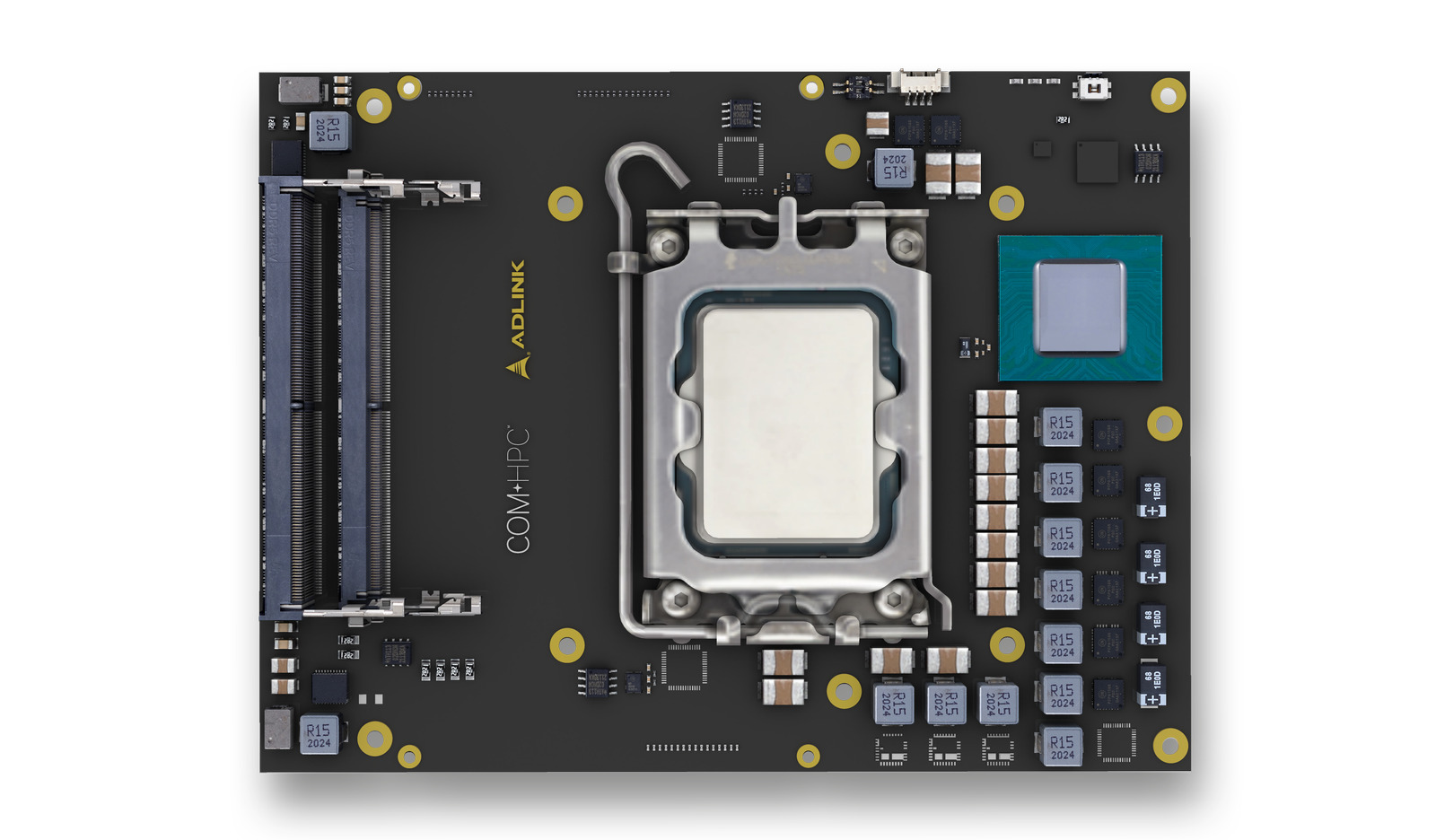
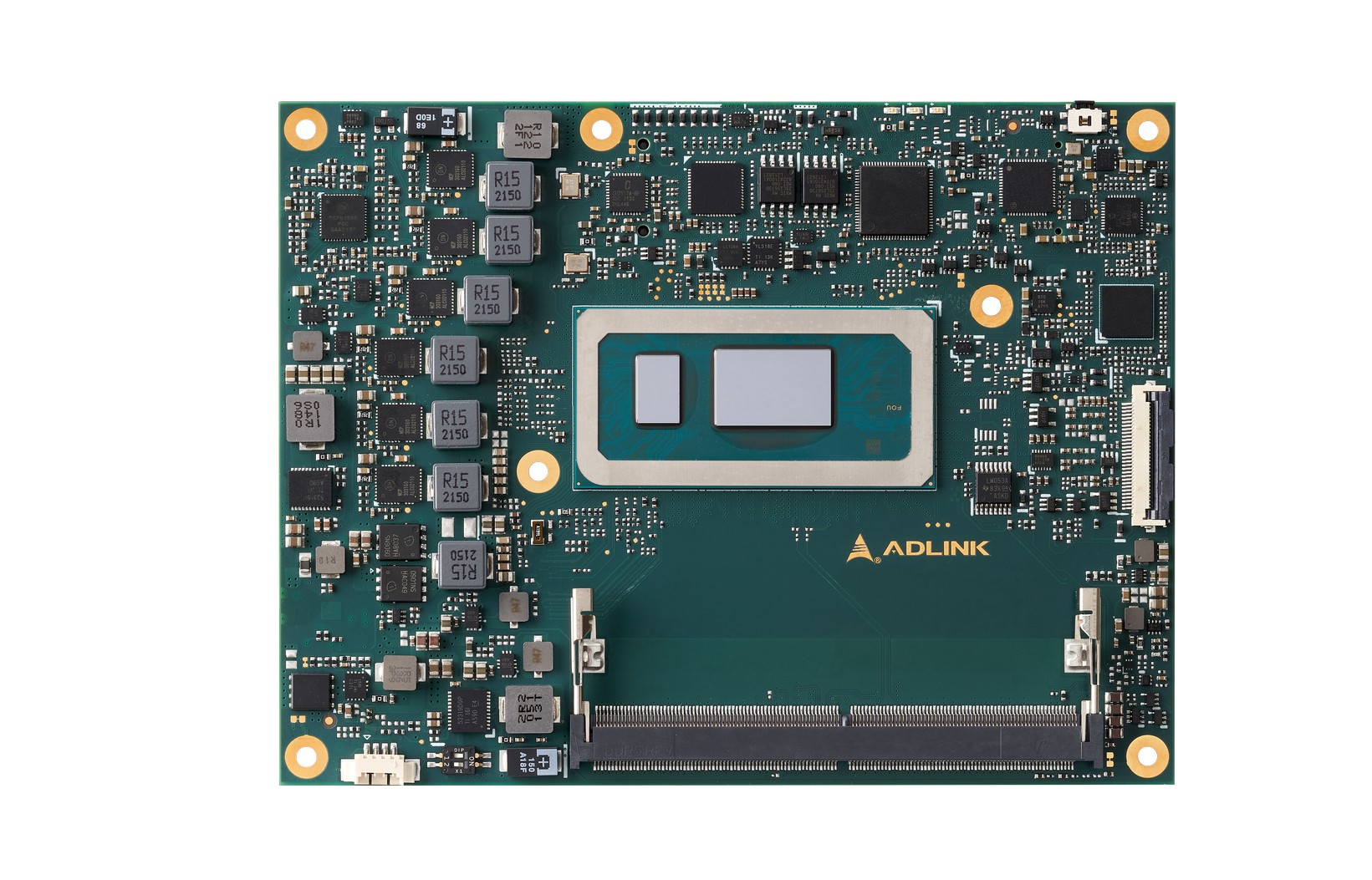
ADLINK Technology Inc., a global leader in edge computing, introduces two new Computer-on-Modules based on the latest Intel® Core™ processors, available in two form factors — COM Express (COM.0 R3.1) Type 6 Module based on Intel® 13th Gen Core™ mobile processors and Client Type COM-HPC Size C module based on Intel® 13th Gen Core™ desktop processors. Utilizing Intel’s advanced hybrid architecture, with P-cores and E-cores, these modules combine power efficiency with performance and fulfill various demanding AI, graphics, and mission-critical IoT applications.
ADLINK Express-RLP provides up to 14 cores, 20 threads, 64GB DDR5 SO-DIMM, PCIe Gen4, and 4 displays or 2 USB4. Realizing high-performance computing at lowered power and exceptional performance per watt, the module is suited for AIoT use cases at 15/28/45W TDP, and also offered in industrial-grade, with extreme rugged operating temperature option.
ADLINK COM-HPC-cRLS showcases up to 24 cores and 32 threads to deliver superior multi-thread and multitasking performance. It harnesses up to 128GB DDR5 SODIMM, and two 2.5GbE LAN. Topping off, the module packs 16 PCIe Gen5 lanes that best performance with fewer lanes than its predecessors in driving next-gen compute-intensive edge use cases, and ultimately simplifying developers’ application-specific carrier designs and reducing time to market effectively.
Both of ADLINK’s two new modules are equipped with Intel® TCC (Time-Coordinated Computing) and TSN (Time Sensitive Networking) support. By which the timely execution of deterministic, hard real-time workloads with ultra-low latency are ensured, TCC brings precise time synchronization and CPU/IO timeliness within a system, whereas TSN optimizes time precision for a synchronized networking between multiple systems.
Built for instantaneous on-device AI applications, these new ADLINK COMs empower developers to realize their future-proof, AIoT innovations, including industrial automation, AMR (Autonomous Mobile Robot), autonomous driving, medical imaging, entertainment, video broadcasting, and more.
ADLINK is also working to provide COM-HPC and COM Express development kits based on ADLINK Express-RLP and COM-HPC-cRLS modules, with carriers supporting USB4 and PCIe Gen5 for on-the-spot prototyping and referencing.
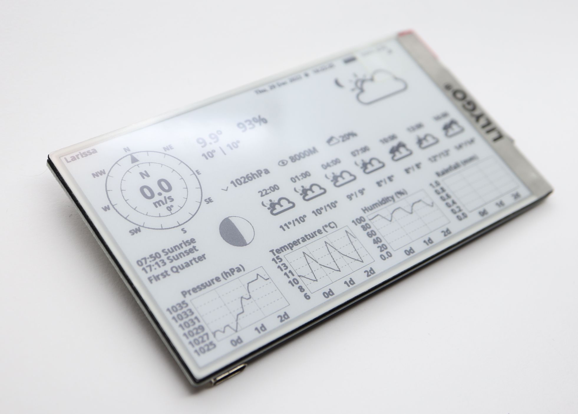
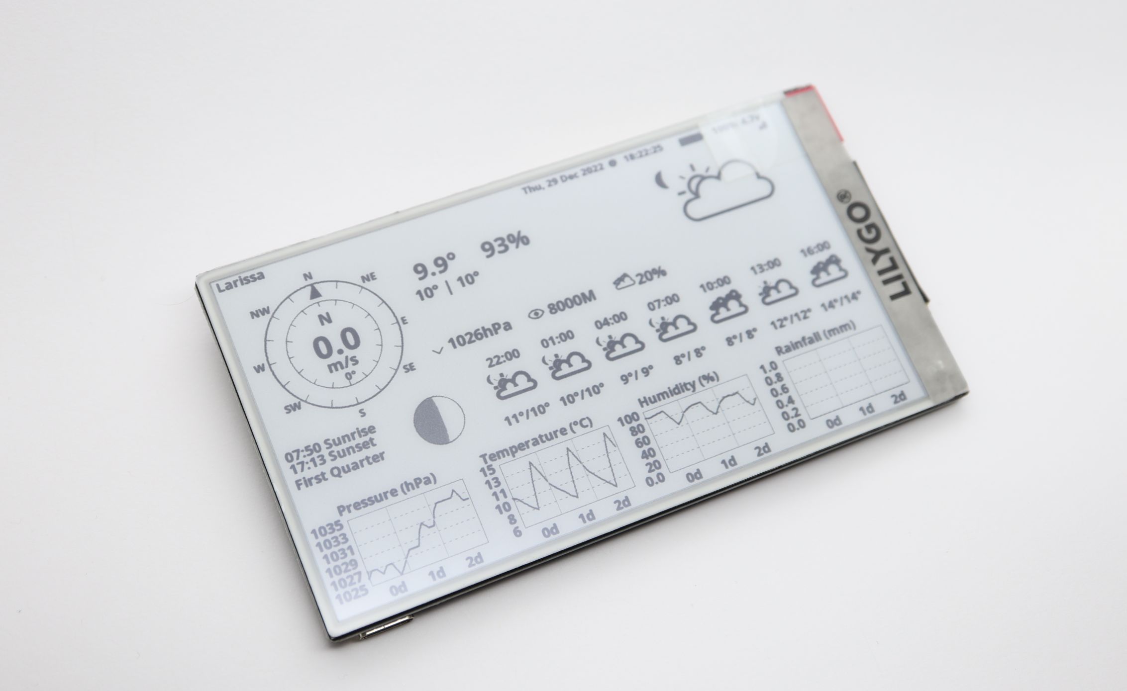
The LILYGO T5 4.7 inchE-Paper ESP32 Development Board is an exciting 4.7″ e-paper display integrated with an ESP32 WiFi/Bluetooth module. The board’s processor is ESP32-WROVER-E with 16MB of FLASH memory and 8MB of PSRAM. The ESP32 module supports Wi-Fi 802.11 b/g/n and Bluetooth V4.2+BLE and can easily be programmed with Arduino IDE, VS Code, or ESP-IDF. The board can be purchased on Alliexpress for 38.33 EUR + shipping or Tindie for 28.13 + shipping. This display is ideal for building a weather station that will fetch weather data from OpenWeatherMap via simple API usage. So in this tutorial, we will follow the steps to make a weather station like the photo above. We will work on a Windows PC to program the display, but the same can be done in Linux or Mac OS.
Specifications
MCU: ESP32-WROVER-E (ESP32-D0WDQ6 V3)
FLASH: 16MB
PRAM: 8MB
USB to TTL: CP2104
Connectivity: Wi-Fi 802.11 b/g/n & Bluetooth V4.2+BLE
Onboard functions: Buttons: IO39+IO34+IO35+IO0, Battery Power Detection
Power Supply: 18650 Battery or 3.7V lithium Battery (PH 2.0 pitch)
First of all, we will need to install the USB to Serial (CH343) Drivers if we don’t have this done previously. Depending on your Windows version you will need:
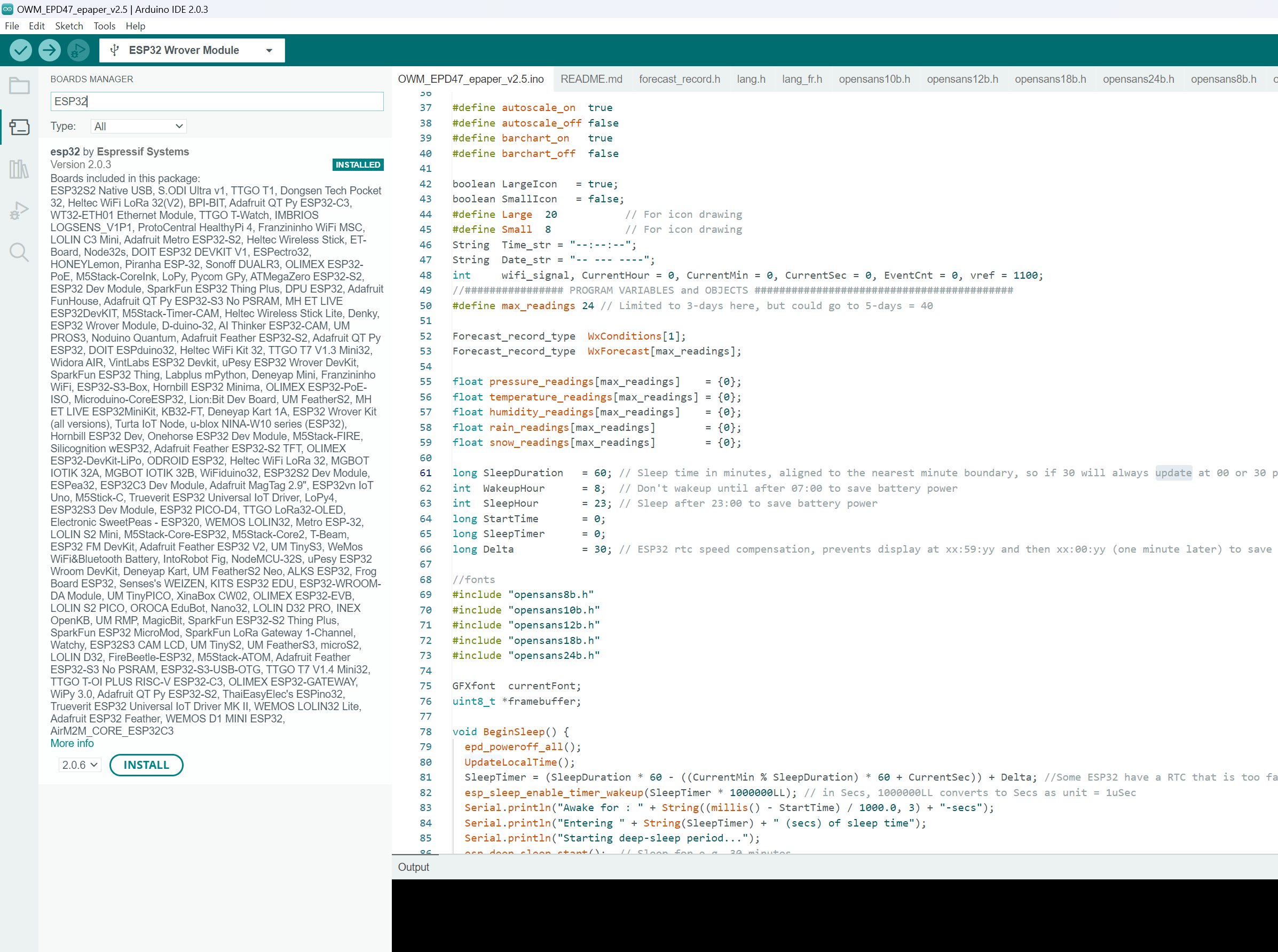
Next click Tools, and select Boards: -> Boards Manager . It will open the left pane with a list of boards. Type ESP32 into the search field. Find ESP32 by Espressif Systems, and click Install.
Preparing the Code
Download LilyGo-EPD47 library to the C:\Users\YOUR_USERNAME\Documents\Arduino\libraries folder on your system:
Download and extract LilyGo-EPD-4-7-OWM-Weather-Display to your directory with Arduino projects. This directory is normally located in C:\Users\YOUR_USERNAME\Documents\Arduino.
The project folder name should match the name of the source code file (OWM_EPD47_epaper_v2.5). This is done to avoid the unnecessary step of moving the files later.
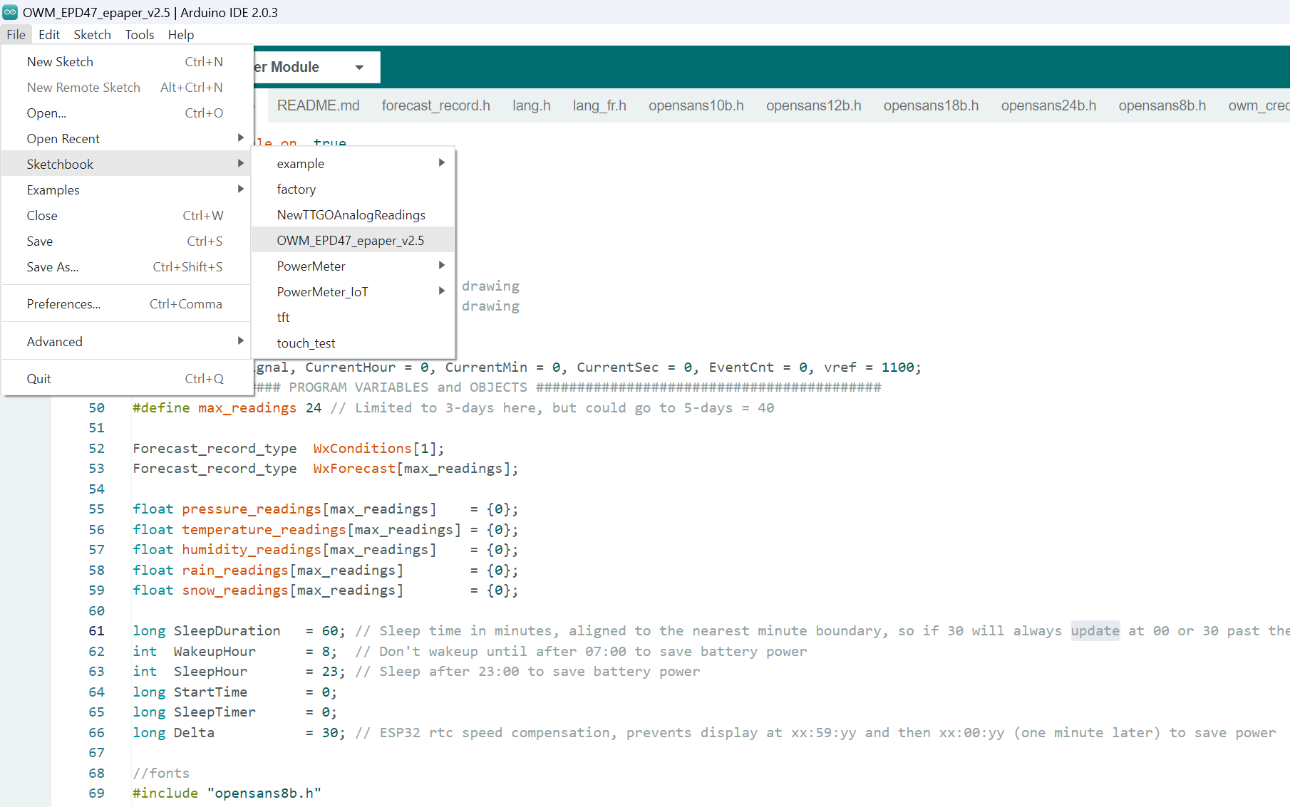
Open Arduino IDE 2.0, click File, -> Sketchbook, -> OWM_EPD47_epaper_v2.5.
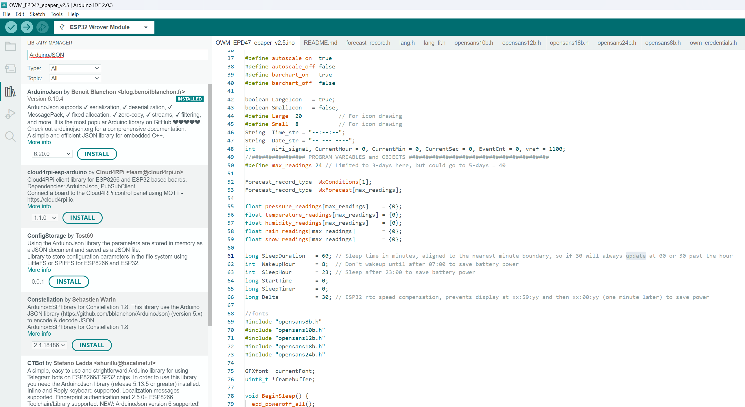
The sketch requires ArduinoJson Library to successfully build.
Click Tools, ->Manage libraries. The pane with Library Manager will open, then type ArduinoJson into the search field. Find ArduinoJson by Benoit Blanchon, click Install.
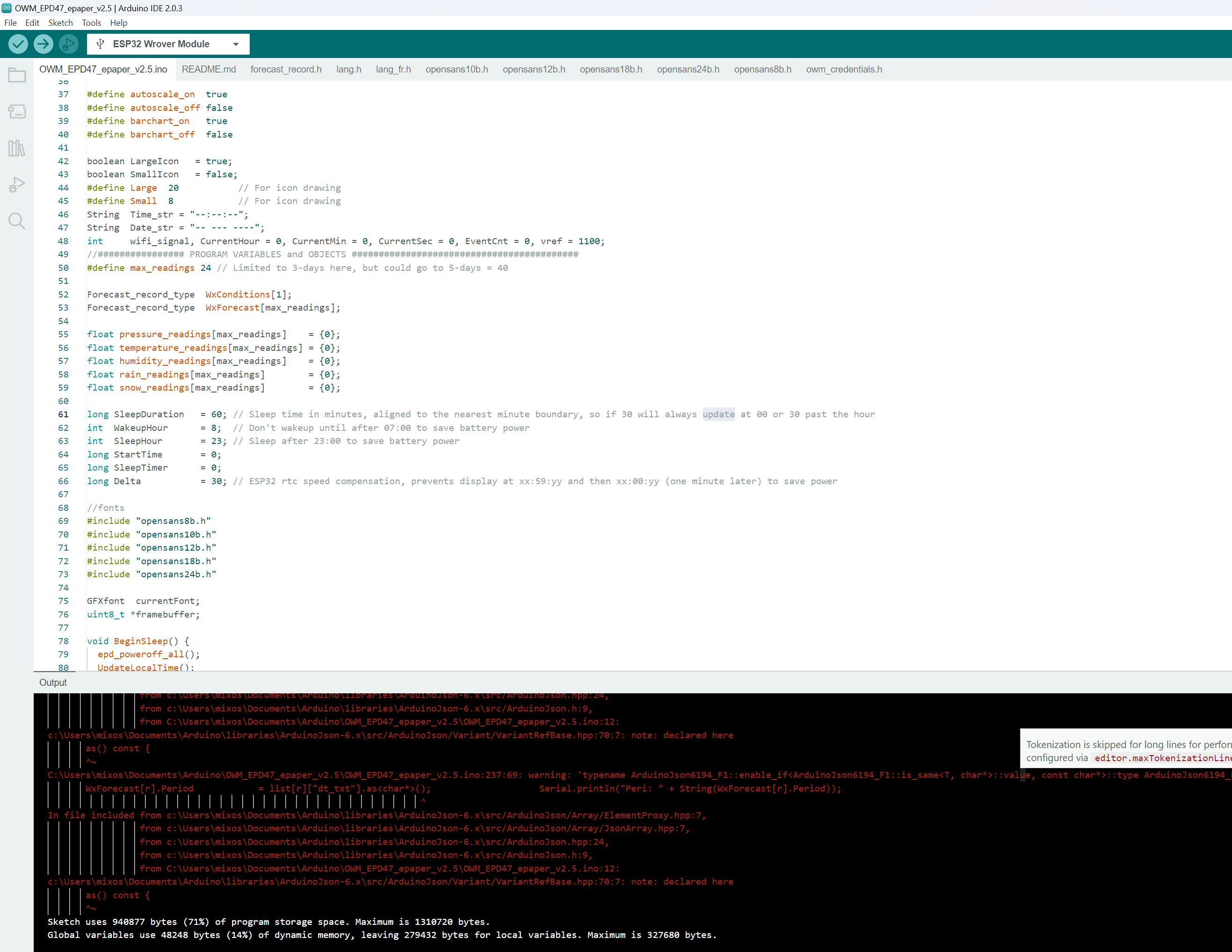
Then click the tick button on the top menu to compile the code. If everything is successful it should show:
Once you verify that the code is compiled you can move on to the next step.
Configuring Parameters
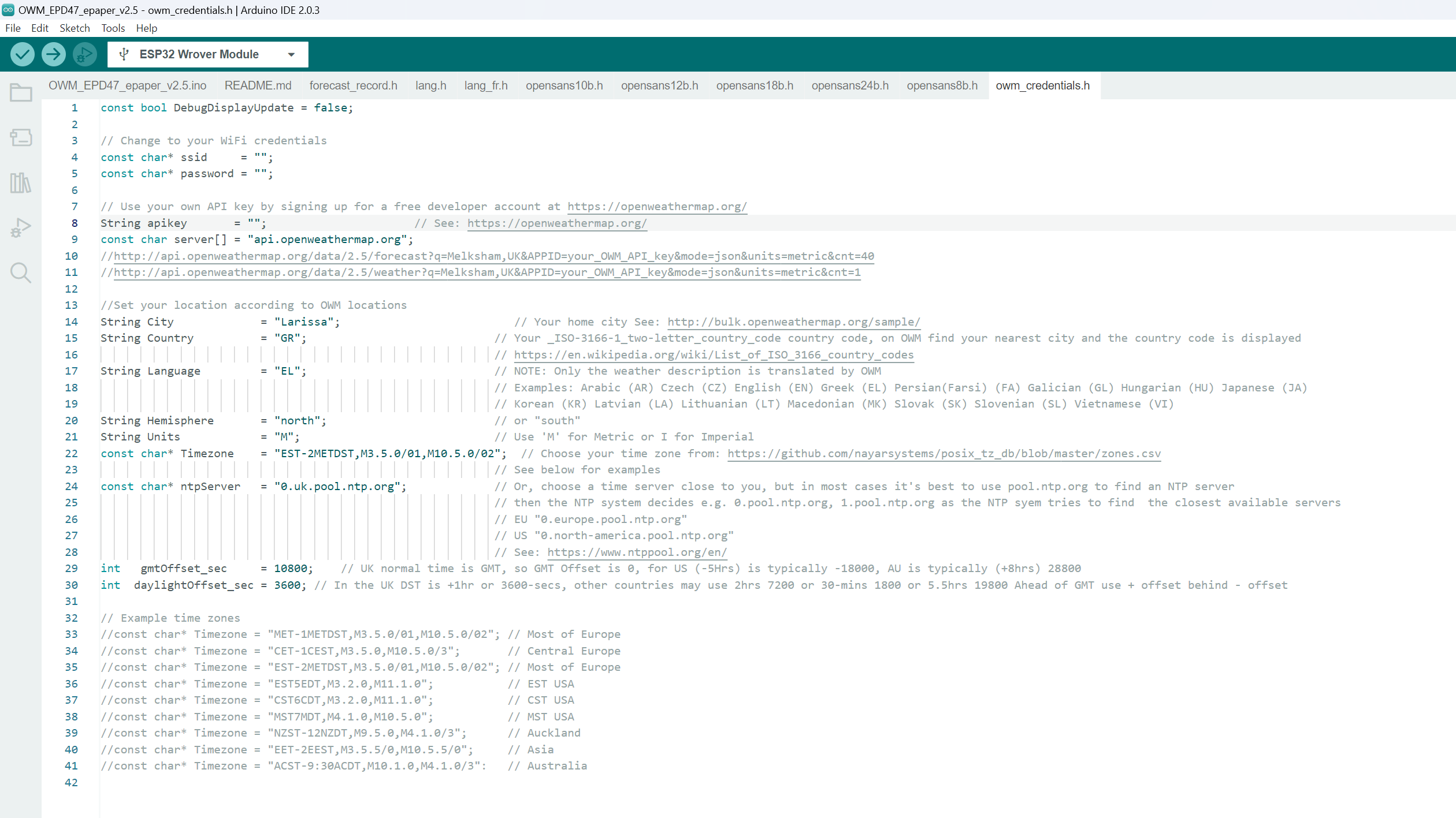
Open the file owm_credentials.h and configure ssid, password, apikey, City, and Country.
The project is fetching data from openweathermap.org so you will need to create a new free account in order to get API key.
Power Saving
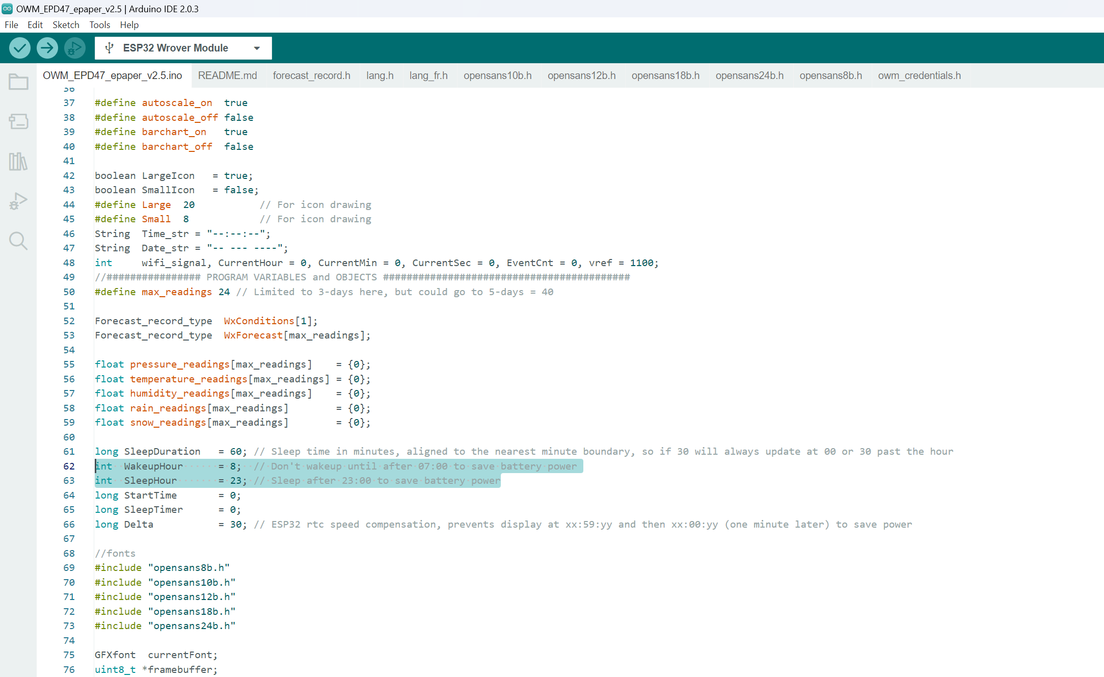
The project code supports power saving, so if you’re flashing in the early before 08.00 or after 23.00, you might notice that nothing appears on the display.
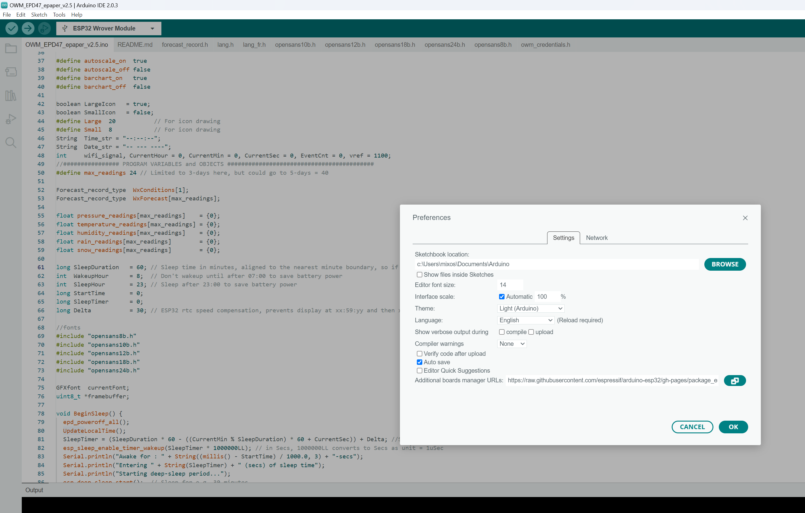
To change the power-saving options open file OWM_EPD47_epaper_v2.5.ino and change WakeupHour and SleepHour to a value that suits your schedule.
Uploading the Code
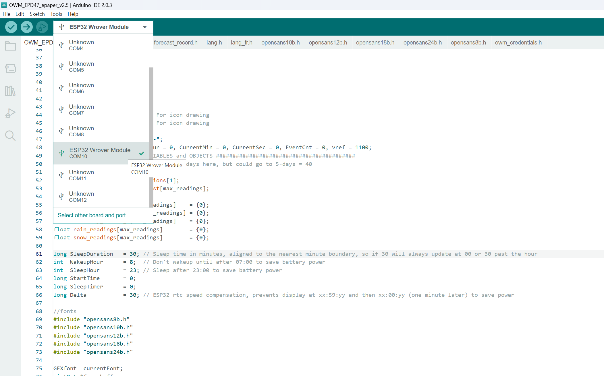
Connect the LilyGO T5 4.7-inch e-paper display to your PC-> Select the board from the dropdown in the toolbar. Search for the ESP32 Wrover module and click Ok.
Click the Upload button.
If the flashing is successful, your weather will be displayed on the e-paper like the photos below.
The Priority Encoder is a combinational logic circuit that produces an equivalent binary code at its output pins, unique to each combination state of its inputs. As discussed in previous articles, an encoder produces a unique binary code that is related to a specific input combination, and the inputs handled by an encoder are given by 2n. The binary code then can be processed through a Decoder to obtain the original input combination. The Priority Encoder works in a similar way and produces a binary code but with the highest priority.
From the Multiplexer article, it is known to connect one of its input lines to only output depending on the address or select lines. The Priority Encoder can be used to produce the output address of select lines with the highest priority. The Priority Encoder with an “n” number of bits can encode 2n input lines. For example, a 2-bit Priority Encoder can encode 22 = 4 input lines. Similarly, the 3-bit & 4-bit Priority Encoders can encode a total of 8 & 16 input lines, respectively. Therefore, the commercial IC packages include 4 to 2, 8 to 3, and 16 to 4 configurations of lines.
The 4-to-2 Bit Binary Encoder
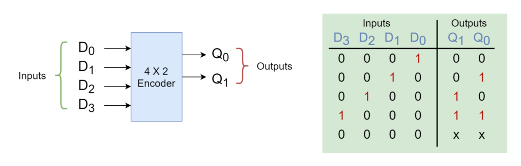
The binary encoder produces an equivalent binary or Binary Coded Decimal (BCD) code of the input line having a logical state of “1”. The binary encoder expects to have only one of the input lines to have a logical state of “1”. In the following figure, a typical 4-to-2 Encoder along with its truth table has been shown.
Figure 1: A 4-to-2 Binary Encoder
The output lines (Q0 & Q1) output a binary code to encode four input lines (D0, D1, D2, & D3). When D0 is “HIGH” then both outputs are “LOW”, similarly, a “HIGH” state of D1 input enables only Q0 to “HIGH”, and other inputs are encoded, accordingly. In an ordinary encoder, there is only one input with a logically “HIGH” state and can produce the wrong output when it has more than one input with a “HIGH” state. For example, when both D1 and D2 are “HIGH” then it would produce an output of “11” which belongs to the input address of D3 which is completely wrong.
The simplest way to overcome such a problem is to prioritize the inputs and when there is more than one input with a “HIGH” state then produce output code corresponding to the input with the highest designated priority only. So, the encoder which prioritizes the binary inputs to produce an equivalent binary code is called a Priority Encoder or P-encoder.
Parity Encoder
The Priority Encoder considers the priority assigned to each input and outputs the binary code at its outputs, accordingly. The output binary code of the input with the highest priority will be produced while all other inputs with lower priority will be ignored. So, by knowing the priority of each input, one can easily designate the address of the currently active input. The Priority Encoder comes in a variety of commercial packages depending on the number of inputs and, most commonly, used is an 8 to 3 Bit Priority Encoder which encodes eight (8) input lines to three (3) bit binary code considering priority.
The 8-to-3 Bit Priority Encoder
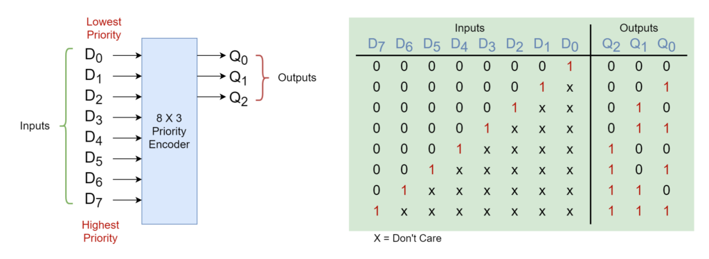
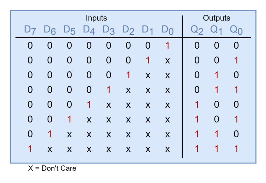
In the following figure, an 8-to-3 Priority Encoder has been shown along with its truth table. The 8-to-3 Bit P-encoders are available in commercial IC packages and 74LS148 is a TTL family 8-to-3 Bit Priority Encoder. The Priority Encoder typically sets the priority of its inputs depending on their ascending order. Considering eight (8) inputs from D0 to D7, the D0 input will have the least priority compared to other inputs and, on the other hand, the D7 will enjoy the highest priority. For example, if inputs D2 and D5 are active, simultaneously, then the input D5 will be given priority over D2 because of its higher order.
Figure 2: The 8 by 3 Priority Encoder
The truth table below shows a number of input conditions as “don’t care” and are labeled as “X”. This means that the output is not affected by any condition of either “0” or “1” at these “X” values. From the truth table, it is also observed that “don’t care” conditions enable the accounting of priority function at each of these input conditions.
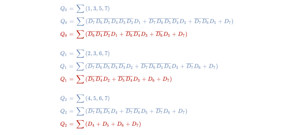
The above truth table gives the following algebraic equations for the outputs of the 8-to-3 Bit Priority Encoder and the equations are simplified further to obtain reduced equations.
The Output Expressions of the 8-to-3 Bit Priority Encoder
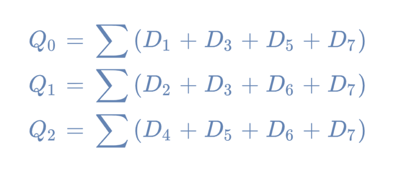
The reduced expressions of the parity encoder are further simplified by ignoring the “don’t care” or zero input conditions.
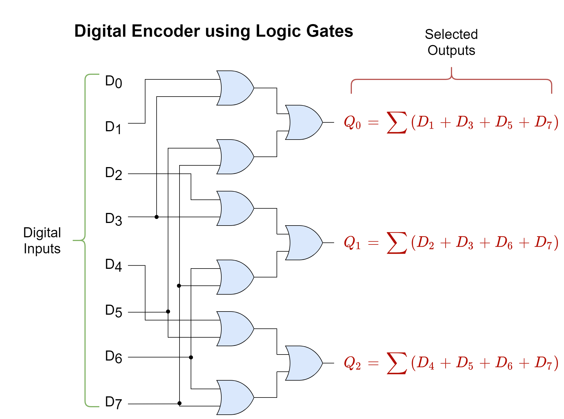
The Logic Diagram of 8-to-3 Bit Priority Encoder
From the above-simplified expressions, following the 8-to-3 Bit Priority Encoder can be constructed as shown below:
Figure 3: The logic diagram of the 8 by 3 Encoder
Applications of Digital Encoders
Digital encoders have a number of applications in digital circuits where a large number of conditions are encoded in smaller data bit sets. The major applications of digital encoders are described below:
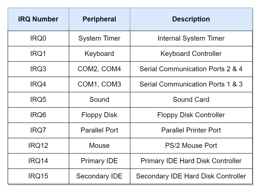
Interrupt Requests
In digital systems, the Priority Encoders are used in connecting different peripherals or services to a microprocessor through interrupt requests. The multiple peripherals or I/O devices such as a keyboard, mouse, printer, scanner, or disk drive are each allocated with a priority level for an interrupt request. The microprocessor on interrupt request checks the interrupting devices and connects with the one having the highest priority and, using this way of communication, the microprocessor knows to which device it is communicating and sets the protocol, accordingly. Using the Interrupt Requests not only alerts the microprocessor or microcontroller that a device wants to communicate but also ensures that the devices are served in order according to their priority levels.
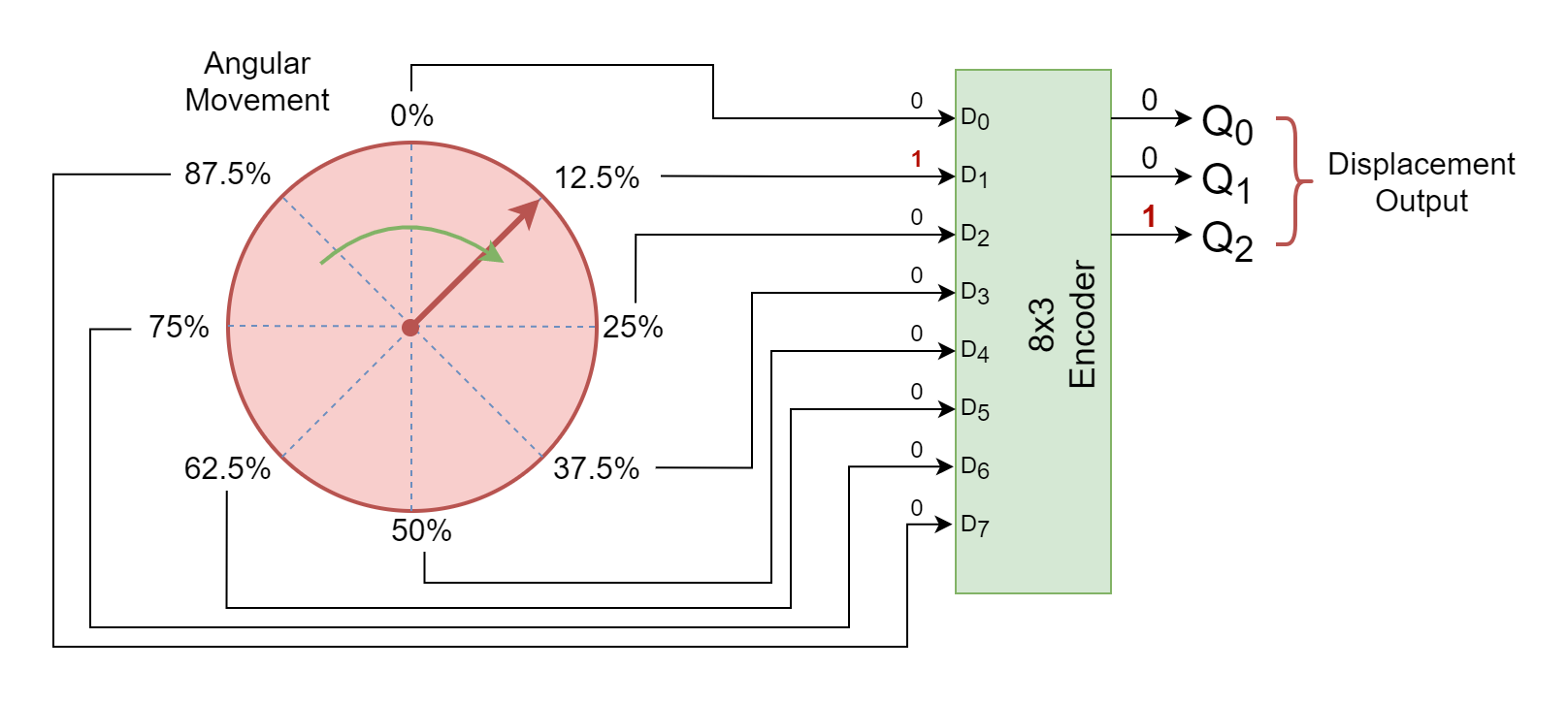
Rotary/ Position Encoder
The Rotary or Position Encoders are frequently used in rotating or mechanical parts to determine the position of a rotating object. The most common applications include robots, rotating knobs, navigation systems, electric gates, etc. The rotational movement is divided into a number of segments or positions which gives the proportion or percentage of total displacement or rotation. Each segment or position drives the input lines of an encoder which produces a binary code of that specific position and is processed in the microprocessor, accordingly. The following figure shows a rotating knob that is divided into eight (8) segments and each segment is given a total percentage of rotation covered. The segments can be indicating to any specific information and can be driven through a sensor such as a compass or motor.
Figure 4: The Rotary or Positional Encoder
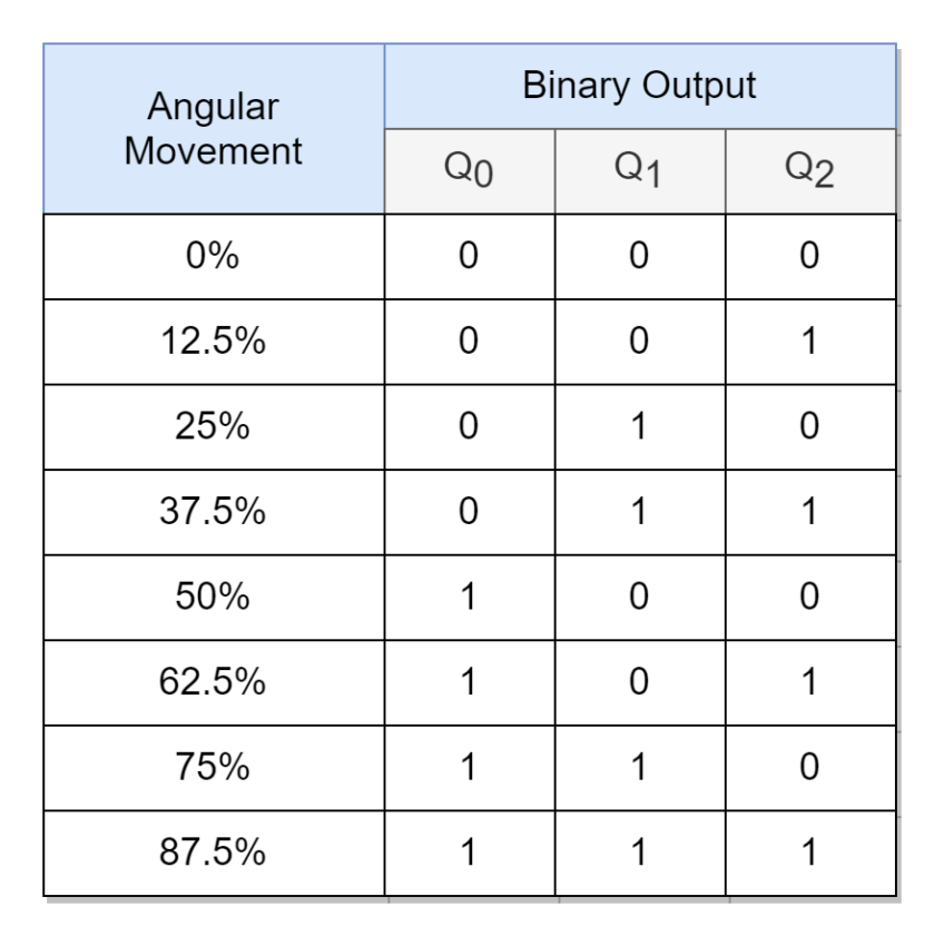
The following table shows the expected output binary code of the above rotary encoder.
Keyboard Encoder
The QWERTY keyboard typically uses 104 keys comprising of alphabets, numbers, special characters, etc., and is not feasible to have a dedicated data channel wired for each specific key. Instead, a Priority encoder is utilized to reduce the number of data wires at the output and the 104 keys of a keyboard are converted into American Standard Code for Information Interchange (ASCII). Each ASCII encoded data comprises of 7-bits which can hold information of 27 = 128 signals or keys. So, whenever a key is pressed on the keyboard, an “ACTIVE” or “HIGH” signal of that key is sent using one of its designated spaces from 0 to 127, and from this computer recognizes which specific key has been pressed on the keyboard.
Conclusion
The Encoder is a combinational logic circuit that produces a specific binary or BCD code at its outputs in response to the active input(s). The Encoder converts 2n inputs to an n-bit specific code and, thus, can help in the reduction of signals for the transfer of information using the Encoder–Decoder combination.
The Binary and Priority Encoders are the most commonly used Encoder types. The Binary Encoder is the simplest form of Encoder and is constructed using OR, or AND gates. However, it is prone to producing the wrong output when more than one active input is encountered.
The Priority Encoder considers the designated priority of each input line when producing output code and, as such, overcomes the constraint encountered during multiple active inputs of a standard Binary Encoder.
The Priority Encoder outputs binary encoded data of the inputs with the highest priority when there are multiple active inputs and ignores the rest of the active inputs.
The Priority Encoders are used widely in digital systems where multiple input and output interfaces are utilized for information transfer. For example, they are used in Interrupt Handlers to process and distinguish between high and low-priority interrupt requests. In Rotary or Positional Encoders, a specific binary code is assigned to determine the rotational or linear movement by designating different portions. Also, Keyboard used an encoder to reduce the number of data wires required for the transfer of data to a computer.
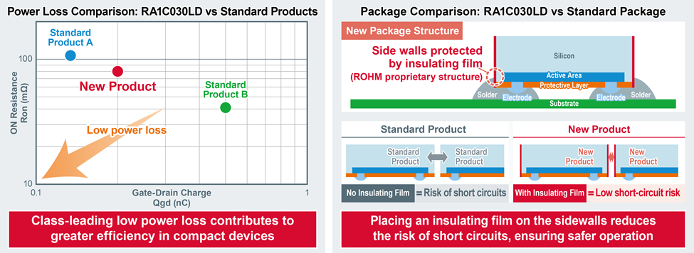
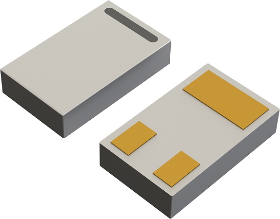
Rohm has introduced a high-efficiency 20-V N-channel MOSFET, targeting small, thin devices including smartphones, wearables, and hearables.
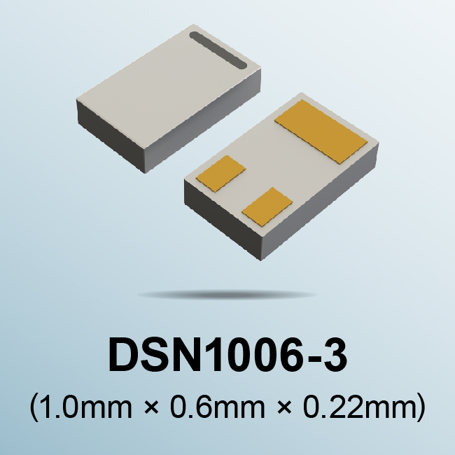
Rohm Semiconductor has developed a compact, high-efficiency 20-V N-channel MOSFET in a DSN1006-3 WLCSP (1.0 × 0.6 mm) package, delivering greater miniaturization for small, thin devices, including smartphones, wearables, and hearables. The RA1C030LD also delivers safer operation thanks to a unique insulated package structure.
Rohm said it leveraged the company’s IC manufacturing expertise to significantly reduce wiring resistance, which has increased with conventional discrete processes, resulting in a compact power MOSFET with low power loss.
In addition, by taking advantage of the company’s proprietary IC process, the RA1C030LD delivers lower power dissipation along with greater miniaturization. Rohm said the figure of merit is 20% lower than standard package products in the same package size (1.0 × 0.6 mm).
The company also offers a unique package structure that provides insulated protection for the side walls, reducing the risk of short-circuit due to contact between components in compact devices that use high-density mounting to save space, said the company. Rohm said it will continue to develop products with lower on-resistance in smaller package sizes that contribute to environmental protection by improving efficiency in compact devices.
The RA1C030LD MOSFET is available via Rohm’s online distributors now: Digi-Key, Mouser, and Farnell. The device also is scheduled for release from additional online distributors.