AAEON Debuts AQ7-ADN Qseven Module Featuring Intel Processor N-Series & MIPI Camera Support

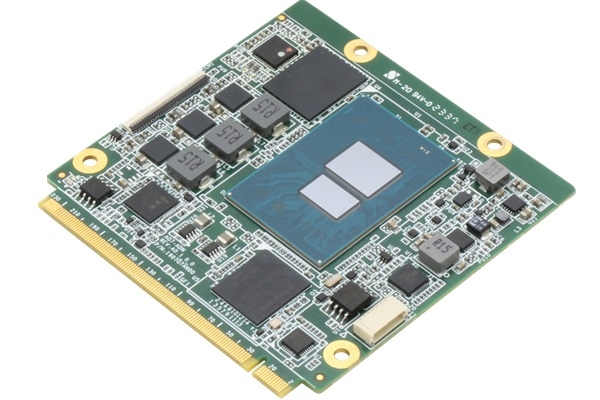
The AQ7-ADN extends AAEON’s adoption of the low-power Intel platform across its Computer-on-Modules range.

Having recently adopted the Intel Atom® Processors x7000E, Intel® Processor N, and Intel® Core™ i3-N305 platforms to a number of its Computer-on-Modules, AAEON has gone a step further by releasing the AQ7-ADN CPU module. The company’s first offering on the diminutive 70mm x 70mm Qseven form factor for a number of years, the AQ7-ADN is available in SKUs featuring a range of CPUs from Intel’s new range, from the 6W Intel® Processor N200 and N50 to the 15W Intel® Core™ i3-N305, offering a variety of performance options to suit different application needs.

Key Features:

  • Alder Lake-N CPU
  • 70mm x 70mm Qseven form factor
  • PCIe [x1] x 4
  • LPDDR5x, up to 8GB

The AQ7-ADN offers up to 8GB of high-bandwidth soldered LPDDR5x system memory for expedited data processing, while staying aligned with the power efficiency of its CPU selection. The module also accommodates to up to 64GB of eMMC for storage, with SATA support and four PCIe slots also available.

The module’s compact dimensions and lightweight 0.26 lb. design make it easy to integrate into space-constrained applications. Despite this, the AQ7-ADN houses a broad selection of connectors suitable for various industrial applications. For peripheral device support, the AQ7-ADN offers an Ethernet connector for Realtek RTL8111H-CG (1GbE), as well as dual USB 3.2 Gen 2 and six USB 2.0 interfaces. The AQ7-ADN also features a 4-lane MIPI CSI connector to enable high-quality image acquisition. In terms of industrial communication protocol support, the module provides users with UART, I2C, SMBus, and an 8-bit GPIO.

Dual display output is available via DP and co-laid eDP and LVDS, which, alongside its Intel® UHD Graphics, makes the AQ7-ADN suitable for applications requiring high-quality visual output, such as Human-Machine Interfaces (HMI). Another clear selling point for the module is its four PCIe slots, which open the door to a range of benefits, including the integration of Wi-Fi, frame grabber cards, and SSDs.

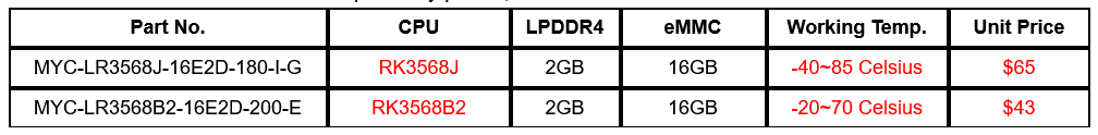
The AQ7-ADN is available for order via the eShop, priced as follows:

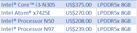
The AQ7-ADN is now in mass production and available for order via the AAEON eShop. For detailed specifications and more information about the AQ7-ADN, please visit its product page on the AAEON website.

MYIR Launches New SOM Based on Rockchip RK3568 Processor

MYIR has launched the MYC-LR3568, a cost-effective System-on-Module (SoM) that is powered by the high-performance, low-power quad-core ARM Cortex-A55 processor RK3568 from Rockchip. This SoC boasts robust Mali-G52 2EE GPU capabilities and supports up to1 TOPs NPU.It also supports various video codecs, including 4K 60fps H.265/H.264/VP9 decoding and 1080P 60fps H.265/H.264 encoding, guaranteeing high-quality video playback and recording for users.

The MYC-LR3568 SOM features a compact 381-pin LGA package design, with dimensions of 43mm x 45mm. It integrates core components such as RK3568J/RK3568B2 processor, 2GB of LPDDR4 memory, 16GB of eMMC storage, EEPROM and PMIC. Additionally, it provides flexibility by allowing customization of optional eMMC capacities of 8GB/32GB and optional memory sizes of 1GB/4GB/8GB. The MYC-LR3568 is compatible with Linux and Debian Operating Systems and caters to a diverse array of applications, such as IoT gateways, NVR storage, industrial control, HMI, cloud terminals, central vehicle controllers, and facial recognition systems.

MYIR provides the MYD-LR3568 Development Board for prototyping and evaluating purposes, tailored specifically for development based on Rockchip RK3568 solutions. It has a carrier board design built around the MYC-LR3568System-On-Module, enabling users to explore the diverse features of the RK3568 processor. The board comes with an extensive range of peripherals and interfaces, including two USB3.0, one USB2.0, two Gigabit Ethernet, two CAN interfaces, a WiFi/Bluetooth module, a Micro SD card slot, an Audio interfaceand a Mini-CSI interface. Moreover, itsupports multiple display interfacessucha as HDMI, Mini-DP, MIPI-DSI, and LVDS.

To further enhance its extensibility, the MYD-LR3568 development board features a 40-pin RPI-compatible expansion interface as well asa MiFAN custom 40-pin expansion interface. Additionally, MYIR offers optional modules to enrich the board’s functionalities, including MY-CAM004M 4ADH-to-MIPI Camera Module, MY-CAM005M MIPI Camera Module, MY-WIREDCOM RPI Module (RS232/RS485/CAN) and MY-LVDS070C LCD Module.

MYD-LR3568 Development Board Top-view


MYD-LR3568 Development Board Bottom-view

MYIR offers two standard configurations for the MYC-LR3568 SOM, tailored to fulfill the diverse requirements of our customers. These modules are competitively priced, and we furthermore extend discounts for bulk orders.

More information about the MYC-LR3568SOM can be found at: https://www.myirtech.com/list.asp?id=768

RealTek RTL8126 5Gbps Ethernet Card Costs $12 and more

The Realtek RTL8126 is a 5Gbps Ethernet controller IC designed for high-speed networking applications. It’s designed to be a low-power, cost-effective product that brings 5Gbps Ethernet connectivity to devices like desktops, laptops, and servers. The IC was first unveiled at Computex 2023 last year and at the time of writing, there are some M.2 modules and PCIe cards available at competitive prices.

There is not much information available about the specific product but, you can purchase it from Amazon for around $12. The module is a 5000Mbps Networking Card B+M Key to a PCIe Adapter. The module is an M.2 PCIe card with a ribbon cable coming out, and with the cable, the RJ45 jack is attached to a PCIe bracket. The card was added recently and there is not much information about it.

It’s very common knowledge that the 10GbE ICs get very hot without adequate cooling but the RealTek RTL8126 chip used here tops at about 82°C under heavy load. There are also divers available for the board and on Windows 11 the drivers are installed automatically. But if you are in Linux you need to install the drivers manually. The drivers are provided by RealTek for this chip, and it will not work seamlessly the new 5GbE controller has not made it to most Linux distributions.

RealTek RTL8126 5Gbps Ethernet Card Specifications

  • Interface: PCIe 3.0 x1
  • Speed: 5 Gbps
  • Compatibility: Cat5e and Cat6 cables
  • Form Factors:
    • M.2 PCIe module with PCIe bracket adapter
    • PCIe x1 card
  • Drivers:
    • Windows: Automatic installation
    • Linux: Requires manual driver installation (available from Realtek)
  • Price:
    • M.2 module: Starting at $12
    • PCIe card: Starting at $12

While choice is limited now, expect a surge in RTL8126 PCIe cards and M.2 modules due to their affordability. The RTL8126 is likely to replace the RTL8125 in upcoming mini PCs. For a 5GbE USB dongle, we’ll need to wait for the RTL8157 controller. Finding a dedicated 5GbE switch might be tricky, as current searches often yield 2.5GbE options. For now, a 10GbE switch might be the best bet.

by cnx-software.

Pico Display Base Board – A Versatile Platform for Raspberry Pi Pico based LCD Projects

The Pico Display Base Board is a compact PCB board designed to simplify the creation of projects using a Raspberry Pi Pico and an LCD screen. The board includes onboard components like buttons and LEDs, as well as ports for additional modules like an RTC module, OLED display, or Infrared receiver. It’s particularly well-suited for projects that require a touchscreen and SD card and is compatible with various programming environments and firmware.

previously we have seen similar products like the Grove Shield for Pi Pico v1.0, the PicoCell 4G boards, and  SB Components Microflex deve boards fell free to check those out if you are interested in those topics.

Pico Display Base Board connects Raspberry Pi Pico to LCD screens (4.3″-7″) and can power the display of up to 5″ directly via Pico and larger ones via USB-C. it also includes headers for onboard components (e.g., LEDs, buttons) and ports for external devices (e.g., OLED display, RTC module). Designed for Raspberry Pi Pico-based LCD projects, the Pico Display Base Board prioritizes easy access to the display and components, supporting both Raspberry Pi Pico and Pico W.

Pico Display Base Board Specifications

  • Compatibility: Raspberry Pi Pico and Pico W
  • Display Interface: 8-bit parallel for LCD, SPI for touchscreen and SD card
  • Display Support: 4.3″, 5″, and 7″ SSD1963-based LCDs
  • Power:
    • Up to 5″ displays: Powered directly from Pico
    • Larger displays: USB-C port or external source
  • Onboard Components: Potentiometer, LEDs, user buttons
  • External Device Ports:
    • DS3231 RTC module
    • 0.96″ OLED display
    • Infrared receiver
  • Programming: Thonny IDE (MicroPython), Arduino IDE, PicoMite/WebMite
  • Additional Features: Jumpers for LCD power and flash chip, 40-pin display port
  • Dimensions: Not Mentioned

The Pico Display Base Board can be programmed with Thonny IDE, Arduino IDE, or BASIC interpreters, for more software information and supported tools resources are available on the PicoDisplay GitHub repository.

The board is priced at around $14 and can be purchased from Tindie, but doesn’t include the Pico microcontroller, LCD, or other components.

Sipeed Showcases Tang Mega 138K Dock with GOWIN Series FPGA

The Sipeed Tang Mega 138K Dock is an advanced and compact FPGA development platform designed to meet both high-performance requirements and cost-effective solutions. Featuring the GOWIN GW5AST RISC-V FPGA, this platform includes a development board with key features such as PCIe x4, a GbE port, and multiple I/Os.

The Tang Mega 138K features the GW5AST-LV138PG484A FPGA with 138,240 logic units, numerous registers, and 12 phase-locked loops. The core SoM board includes an integrated RISC-V processor clocked at 800MHz, along with 4Gbit DDR3 x2, 128Mbit flash, and advanced BTB connectors. It also integrates components such as DC-DC converters, a DDR power IC, and user-configurable keys.

The Tang Mega 138K Dock board integrates a variety of high-speed and versatile interfaces, including Gigabit Ethernet and USB 3.0. It features connectors for DVI in/out, stereo audio, a MIC array, and MIPI DPI RGB LCD, among others, making it adaptable for various applications. The product page indicates that the board is fully compatible with PCIe 2.0, featuring an external x4 interface with transfer rates up to 20GT/s. It also includes a USB3 interface provided by the WCH CH569W, supporting USB-C cables with transmission rates up to 5Gbps for high-speed communication.

The board also supports power management with a 12V DC input, battery connection, and charge/discharge management PMU. Additionally, it includes a microSD slot, gamepad connectors, and multiple user-configurable keys. Last year, the company launched the Sipeed Tang Mega 138K Pro version, priced at $119, which measures 70x50mm and includes a PCIe 3.0 x8 interface. In contrast, this version is available for $69, measures 34x45mm, and offers a PCIe 2.0 x4 interface, ensuring backward compatibility. The Pro version is suitable for high-speed interface development scenarios, while this version is ideal for applications requiring high-cost performance and limited volume according to the product page.

The 138K Pro Dev Kit is equipped with high-speed interfaces such as PCIe, M.2, SFP, and more PMOD and HDMI ports than the standard version, making it suitable for extensive development needs. On the other hand, the 138K Dev Kit reduces the area and price by a quarter while maintaining essential functionalities like universal pin interfaces, USB3 interfaces, and handheld interfaces.

Specifications for the Sipeed Tang Mega 138K Dock include:

  • Memory/Storage: 1G DDR3, 1x Micro SD slot
  • Display: DVI In/Out, 1x RGB LCD
  • Audio: 1x 3.5mm audio jack, 2x Speakers, 1x Mic array
  • Camera: 1x DVP camera port
  • Expansion: PCIe x4
  • Connectivity: GbE port
  • I/O Interfaces: 2x PMOD connectors, 4x 20-pin headers, 3x Buttons, 6x DIP switches
  • Other Features: RGB LED(WS2812 + LED strips), 4-pin fan connector
  • USB: 1x USB 3.0 Type-C port, 1x USB-A port
  • Power: 12V DC Input, Battery connector (3.7V)
  • Mechanical: 35 x 45mm (SoM board), 129 x 84.51mm (Dock board)

The SoM board is available for $68.89, while the Dock development kit, which includes additional accessories, is available for $129.60 on the Sipeed store on AliExpress.

An Arduino Nano Clone in a DIP-Sized Footprint

Nano DIP 33x10mm

The Arduino Nano and its many clones are staples in the world of development boards, often found within arm’s reach of any electronics enthusiast. However, even the compact Nano can take up valuable space on solderless breadboards during prototyping. To address this, [Albert van Dalen] has created a miniaturized version of the Nano called the “Nano DIP.” Measuring just 33 mm x 10 mm, the Nano DIP is about the same size as the ATmega328 on the Arduino Uno, making it a delight for those who appreciate miniaturization.

Arduino Nano DIP features:

  • DIP26 size, 33 x 10 mm
  • Arduino Uno compatible
  • ATtiny3217 instead of the ATmega328P
  • 21 I/O pins
  • 12 x 10 bit ADC channels
  • Supply voltage 1.8V – 5.5V
  • Supply voltage V+ max18V
  • Clock 16MHz (for compatibility reasons, the max frequency is 20MHz)
  • Straightforward pinout

Smallest complete Arduino board

Additional features compared to the Arduino Uno

  • 1 x fast 350ksps 8-bit real DAC
  • The USB supply pin is protected by an ideal diode that doesn’t have a 0.7V voltage drop
  • A 2-pole header, which is connected to D2, can be used as a jumper. Use pinMode(INPUT_PULLUP)
  • The LED at D0 can be disabled by a jumper

The Nano DIP is built around an ATtiny3217 microcontroller and retains nearly all the features of the original Nano. It includes a USB port, a reset button, built-in LEDs, a 5V regulator, and a preloaded bootloader. The 350-kilosamples-per-second 8-bit DAC is a standout feature, although it comes at the cost of losing external crystal pins and a 3.3V regulator.

To make the board affordable to manufacture, [Albert] opted for a minimum component size of 0402, presenting a significant design challenge. The microcontroller barely fits between the header pin pads, and the Micro USB jack had to be a vertical-mount type. Despite these constraints, the Nano DIP performs admirably, offering the same functionality as a standard Nano in a much smaller footprint. If you are looking to free up space on your breadboard without sacrificing functionality, the Nano DIP is an excellent option to consider.

LILYGO T3S3 E-Paper: ESP32-S3 WiFi & BLE SoC with LoRa Module and 2.13-inch E-Paper Display

LILYGO

The LILYGO T3S3 E-Paper is an innovative development board that combines the ESP32-S3 WiFi and Bluetooth LE SoC with a 2.13-inch e-Paper display and an SX1262 LoRa module, making it suitable for off-grid messaging even in sunlight.

Specifications:

  • Wireless Module: ESP32-S3-WROOM-1U
  • SoC: ESP32-S3FH4R2 dual-core Tensilica LX7 microcontroller @ up to 240 MHz
    • 2.4 GHz 802.11n WiFi 4 and Bluetooth 5.0 LE connectivity
  • Memory: 2MB PSRAM
  • Storage: 4MB SPI flash
  • Antenna: IPEX connector
  • Additional Storage: MicroSD card slot

Display:

  • Type: 2.13-inch e-Paper (DEPG0213BN)
  • Resolution: 250×122 pixels
  • Size: 48.55 x 23.70 mm

Wireless:

  • LoRa Module Options:
    • SX1262 @ 868/915 MHz
    • SX1276 @ 868/915 MHz
    • SX1280 @ 2.4 GHz
  • Antenna: IPEX1 or SMA connector

USB:

  • Type: USB Type-C port for power and programming

Expansion:

  • Connectors:
    • 4-pin Qwicc connector
    • 2x 13-pin headers (unpopulated) with up to 21x GPIO, 2x UART, 4x ADC, SPI, Touch, 4x clock outputs, 5V, 3.3V, and GND

Miscellaneous:

  • Switches: On/off switch, reset, and boot buttons
  • Power Supply:
    • 5V via USB Type-C port
    • 2-pin JST connector for LiPo battery with ADC pin for battery voltage
    • TP4065B battery charger chip
  • Dimensions: 67 x 29 mm

The GitHub repository provides Arduino samples for LoRa P2P communication, LoRaWAN, display, sensors, and more. This repository also points to third-party open-source firmware that could eventually work with the board, including SoftRF for general aviation proximity awareness, Paxcounter for passenger flow metering, and Meshtastic for off-grid messaging. However, the e-Paper display might not be supported out of the box. Still, it could be compatible with the Arduino sketches for the LILYGO T5 using the same 2.13-inch e-Paper display (codename: DEPG0213BN).

LILYGO-T3S3-E-Paper pinout diagram

The T3S3 E-Paper ESP32-S3 board can be purchased on AliExpress for $29.98 including shipping with the SX1262 RF transceiver and accessories shown above. Other versions with SX1276 or SX1280 are not available yet including from the company’s Amazon store and own store where I can only find the T3S3/T3-S3 variants with an OLED display.

ThunderScope: The First Thunderbolt-Compatible Open Source Software Defined Oscilloscope

ThunderScope

ThunderScope is a revolutionary open-source oscilloscope designed to leverage the power of Thunderbolt technology, enabling real-time sample data streaming to your computer at speeds exceeding 1 GB/s. By utilizing the advanced processing capabilities of modern devices, ThunderScope eliminates the limitations associated with traditional oscilloscopes.

ThunderScope redefines the oscilloscope user experience with a modern, multi-window layout that supports contemporary accessibility features. This user-friendly interface replaces the cramped UI of traditional oscilloscopes, making measurements quick and easy. Sample memory is expanded from megabytes to gigabytes, and the fixed list of protocols and trigger types is replaced with a continuously growing repository.

ThunderScope Board

Designed with students, hobbyists, and professionals in mind, ThunderScope offers unique benefits for each user group. For students, its compact form factor and modern UI are perfect for on-the-go use, providing a portable solution that fits into a laptop bag. High-resolution display compatibility and easy screenshot capabilities streamline lab report creation. Hobbyists and makers will appreciate that ThunderScope comes fully equipped, eliminating the need for hardware hacking to unlock additional features. As an open-source platform, it invites users to modify and enhance the device itself. For professionals, custom protocols and automated measurements can be easily integrated into ThunderScope’s software. The ability to stream triggered data to MATLAB facilitates advanced analysis.

Key features of ThunderScope include its compact design, which allows users to control and power their entire test setup with a laptop and store it conveniently in a laptop bag. The flexible bandwidth of ThunderScope’s channels, rated up to 350 MHz, fully utilizes the ADC’s 1 GS/s sample rate. This allows for 100 MHz on four channels, 200 MHz on two channels, or 350 MHz on a single channel. ThunderScope ensures it is always up to date by streaming samples to your device for processing, giving users access to the latest triggers, protocols, and measurements. The powerful Artix-7 FPGA, specifically the XC7A35T-2CSG325C from Xilinx, enables 1 GB/s real-time data streaming. With 6.2 GB/s total data throughput capacity, this FPGA ensures no data is missed while managing all board operations.

The technical specifications of ThunderScope are impressive, featuring four channels, an analog bandwidth of 350 MHz, a sample rate of 1 GS/s, and an 8-bit resolution. The voltage ranges from 1 mV to 10 V per division with a 1× probe, and the memory depth can be as many gigabytes as you can allocate. It is compatible with both Windows and Linux operating systems.

ThunderScope is completely open source, and all development and design decisions are detailed on its hackaday.io page. This transparency allows users to understand and modify every aspect of the oscilloscope, fostering a community of innovation and collaboration.

ThunderScope transforms how we approach oscilloscope use by combining Thunderbolt technology, open-source flexibility, and modern design. Whether you’re a student, hobbyist, or professional, ThunderScope offers a powerful, versatile tool for your electronic testing and development needs. Sign up on the ThunderScope page to stay updated and be part of this exciting project.

ODrive Micro: High-Performance, Ultra-Compact Servo Motor Drive for Precise Robotic Motion

Odrive micro rear

ODrive Robotics has introduced the ODrive Micro, an ultra-compact, high-performance servo motor drive designed to simplify precise robotic motion. Building on ODrive’s robust software and hardware ecosystem, the ODrive Micro offers unparalleled integration for next-generation robotic applications. With compatibility for a wide range of brushless motors and an intuitive plug-and-play web UI, it’s never been easier to build sophisticated robotic systems.

ODrive Micro is engineered for easy setup and versatile integration. Its onboard magnetic angle sensor allows for direct mounting on the back of your motor, eliminating the need for a separate encoder. Simply connect it to a 10-30V power source and utilize the convenient daisy-chained CAN connector to get started.

ODrive Micro

If your application uses a gearbox with an output encoder or cannot utilize the onboard magnetic angle sensor, ODrive Micro also supports hall, quadrature, and SPI encoders. This flexibility allows for both motor commutation and dual-encoder load positioning using external encoders.

ODrive Robotics aims to make precision, high-power motion control accessible and affordable. The ODrive Micro encapsulates a decade of motion control expertise in a compact form factor, delivering up to 180W of power in just 10 cm². This miniaturized version offers the same reliability and performance as the larger ODrive Pro and ODrive S1, making it ideal for applications requiring high precision and power without the bulk.

Odrive Micro with terminal blocks and magnet

The ODrive ecosystem supports CAN, offers robust software libraries, and features an intuitive GUI, enabling rapid project setup and execution.

Brushless servomotors outperform stepper motors in power density and have greater service life and reliability than brushed motors. With closed-loop encoder feedback, brushless servomotors provide superior precision, making them the preferred choice for high-performance applications.

ODrive Micro Features & Specifications

  • Form Factor: 32 x 32 x 7.5 mm
  • Motor Compatibility: BLDC (brushless DC), PMSM/PMAC (permanent magnet synchronous/AC), and ACIM (AC induction) motors
  • Power: Up to 180W peak, 100W continuous
  • Voltage:10-30V operation (32V max)
  • Current: 3.5A continuous (Ta=25°C), 7A peak
  • Encoder: Onboard magnetic encoder for back-of-motor mounting
  • Control Modes: Torque, velocity, position, and trajectory control
  • External Encoder Support: Hall, incremental, and SPI encoders
  • Interfaces: CAN and USB
  • Software: Shared architecture with all current-generation ODrives, including web GUI support

Designed for maximum reliability and longevity, the ODrive Micro has undergone extensive endurance testing. It features integrated protection measures, including overvoltage and overcurrent protection, and encoder slip detection, ensuring the safety of your motor, robot, and the drive itself. Each ODrive Micro unit undergoes comprehensive end-of-line factory testing to guarantee top performance right out of the box.

ODrive Robotics will publish the ODrive Micro’s schematics and related files to foster learning and enhance the device’s utilization. The entire software suite is open source, including the Python library, CAN communication protocols, and Arduino examples, which will be available after campaign orders are fulfilled.

Sign up at the top of the ODrive Robotics page to receive notifications about the campaign launch and other updates. ODrive Robotics ensures that all communication is relevant, with the option to unsubscribe at any time.

With ODrive Micro, you can transform any brushless motor into a high-precision servomotor, fitting precision and power into every corner of your robotic projects.

From gimbal motors to NEMA BLDCs, gear motors to drone motors, the ODrive Micro is ready to power your innovations.

A crowdfunding campaign is ongoing and has 43 days to go.

LILYGO T-Energy-S3 ESP32-S3 Dev Board Features An 18650 Battery Holder

LILYGO T-Energy-S3 is an ESP32-S3 powered development board with an 18650 battery holder, a USB-C port for charging and programming.

LILYGO T-Energy-S3 is an ESP32-S3 WiFi and Bluetooth-enabled IoT development board with an 18650 battery holder, a USB-C port for charging and programming, and plenty of I/Os thanks to two 20-pin GPIO headers and a Qwiic connector. The main attraction of this board is its 18650 battery holder which this dev board can be used for battery-powered applications.

Previously we have written about many similar batter operated development boards like the ESP32 PowerFeather, the Beetle ESP32-C6, the Nessie Circuits Riotee platform, and much more, feel free to check those out if you are looking for similar products.

LILYGO T-Energy-S3 Specifications

  • Model: T-Energy-S3
  • MCU: ESP32-S3-WROOM-1
    • Chip: ESP32-S3-R8
    • PSRAM: 8MB (Octal SPI)
    • Flash: 16MB
  • Power: Equipped with an 18650 lithium battery
  • Charging Chip: HX6610S
  • Charging Protection Chip: IP3005A
  • Programming and Development:
    • PlatformIO: Supported on Visual Studio Code
      • Supported Version: espressif32-v6.5.0
    • Arduino IDE: Supported
      • Supported Version: esp32_v2.0.14
  • Connectivity:
    • WiFi STA
  • Programming Environment Setup:
    • PlatformIO:
      • Install Visual Studio Code
      • Download and install PlatformIO IDE extension
      • Open the project and configure platformio.ini
    • Arduino IDE:
      • Install Arduino IDE
      • Download and configure ESP32 board files from Espressif Systems
      • Set up libraries and board configurations
  • Pin Overview:
    • Battery Voltage Measurement Pin: IO3
  • Additional Information:
    • License: GPL-3.0
    • Contributors: Llgok, LilyGO

LILYGO provides documentation for Arduino and PlatformIO, including basic sketches for deep sleep and WiFi station mode, along with a test program for WiFi and GPIOs. The GitHub repository includes datasheets and a PDF schematic. Typically, with LILYGO hardware, you need to develop your own firmware, except for their Meshtastic-compatible boards and devices for messaging and GPS sharing.

LILYGO T-Energy-S3 Can be purchased from Aliexpress where it will cost around $16.98 including shipping.

TOP PCB Companies