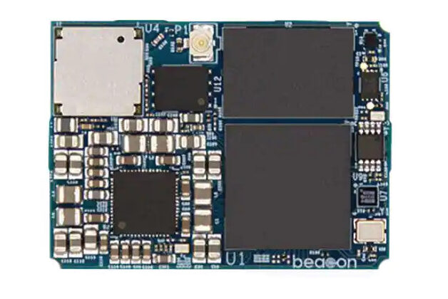
Beacon EmbeddedWorks’ wireless SoM features NXP’s i.MX 8M mini processor and Wi-Fi 5 and Bluetooth® 4.2 connectivity
Beacon EmbeddedWorks’ i.MX 8M Mini/Nano system-on modules (SoMs) can help customers get their product to market faster and reduce design risk. The multicore architecture of NXP’s i.MX 8M Mini/Nano applications processor provides the platform to develop a portfolio of devices on a single hardware design. The i.MX 8M Mini/Nano SoM provides security, high-performance multimedia processing including 3D graphics and high-definition video, power-efficient processing capabilities, and wireless connectivity. Beacon EmbeddedWorks is a leader in designing and developing SoMs with wireless technologies, low-power capabilities, and small form-factors. Board support package (BSP) options are continuously updated with versions of Linux, Android, and real-time operating systems. With a low stack height and compact footprint, the i.MX 8M Mini/Nano SoM is an excellent choice for next-generation medical, military, aerospace, and industrial applications where space is at a premium.
Features
Processor options
Mini: NXP i.MX 8M Mini processor with up to four Arm® Cortex®-A53 cores running up to 1.8 GHz plus an Arm Cortex-M4 core running up to 400 MHz, GPU (GCNanoUltra + GC320), and VPU
Nano: NXP i.MX 8M Nano processor with up to four Arm Cortex-A53 cores running up to 1.5 GHz plus an Arm Cortex-M7 core running up to 750 MHz and GPU (GC7000UL)
Embedded memory
Mini: up to 8 GB of 32-bit wide LPDDR4 memory
Nano: up to 4 GB of 16-bit wide LPDDR4 memory
eMMC, configurable
Quad SPI NOR Flash, configurable
Network connectivity
Wi-Fi 5 (802.11a/b/g/n/ac)
Bluetooth 4.2
BLE support
Ethernet 10/100/1000 MAC + PHY
Security
Integrated secure element for end-to-end security
USB
Mini: two USB 2.0 high-speed on-the-go
Nano: one USB 2.0 high-speed on-the-go
Display
MIPI DSI (up to four lanes)
Camera
MIPI CSI-2 (up to four lanes)
Audio
Mini: up to three synchronous audio interfaces (SAI) with support for 9 Tx and 13 Rx lanes
Nano: up to two synchronous audio interfaces with support for 1 Tx and 5 Rx lanes
S/PDIF input and output
Up to eight channel pulse density modulation (PDM) inputs
PCIe
Mini: 1x PCIe Gen 2.0, 1-lane
Serial I/O
Up to three UART interfaces
Up to three I²C interfaces
Up to two SPI interfaces operating as either master or slave
GPIO
Up to 87 multiplexed GPIOs supporting various peripherals such as PWMs, SDIO, UART, SPI, and I²C
RTC
Onboard ultra-low power real-time clock (RTC)
Debug
JTAG support
Mechanical
Dimensions: 28 mm x 38 mm
Weight: 7.7 g
Compliance
RoHS compliant
Reach compliant
Wi-Fi and Bluetooth are pre-certified for FCC and ISED
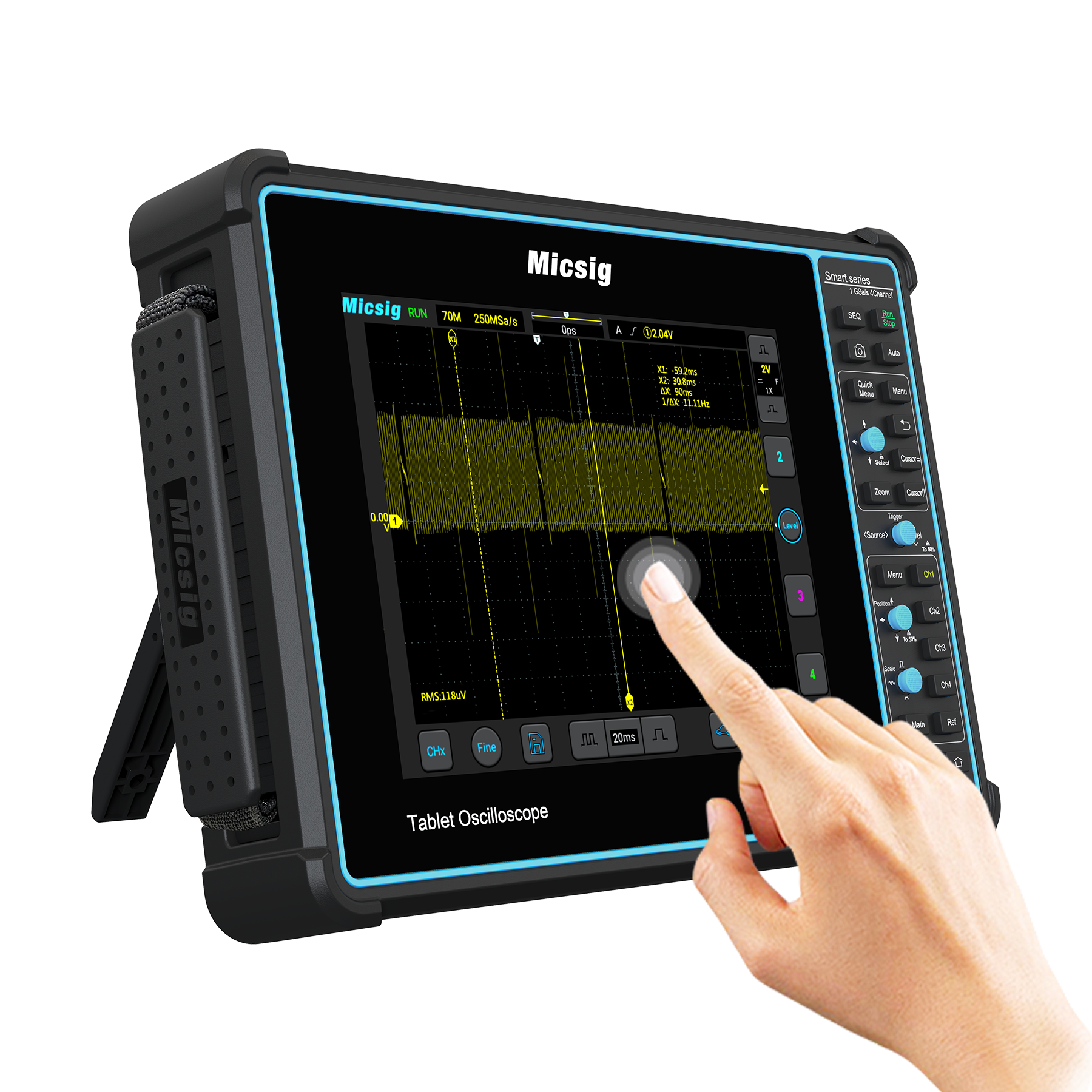
Micsig’s SATO1004 is a four-channel automotive oscilloscope with a comprehensive list of pre-set vehicle-related tests.
The instrument features 100MHz bandwidth, 1Gsample/s (in single channel mode), 32Mpoint memory and up to five hours of mobile use from its built-in battery, or continuous use from its 12V power adaptor.
“SATO1004 is a professional vehicle testing tool for evaluating CAN, LIN, Flex ray and K line networks, and sensors for: ABS, accelerator pedal, throttle position, fuel pressure, air flow meter, crankshaft, camshaft, knock, MAP; as well as testing 12 and 24V charging and start, charging ripple, cranking current sensors, actuators and ignition,” according to distributor Saelig, which is stocking the instrument.
The 8inch 800 x 600 touchscreen has touch, drag and swipe, and shares control of the scope with knob-and-button control. An HDMI output is available to reproduce the display on a larger screen or projector. “Live screen images can be transmitted to an external projector when the oscilloscope is connected to a LAN or WiFi network. The scope can display or be remotely controlled via Wi-Fi, LAN or USB, via a PC or an Android or iOS mobile device,” said Saelig.
As well as the serial busses above, bus trigger and decode features include: UART, SPI and I2C, then 1553B and ARINC 429 trigger and decode are options.
The Standard Kit version of the scope comes with 2x passive probes, 4x BNC-banana cables, 2x pair needle probes, 2x pair alligator clips, a power adaptor with mains cable and a screen protector.
The master Master Kit has the above, plus a secondary ignition pick-up, 2x multimeter-style probe tips and a hard-shell carrying case.
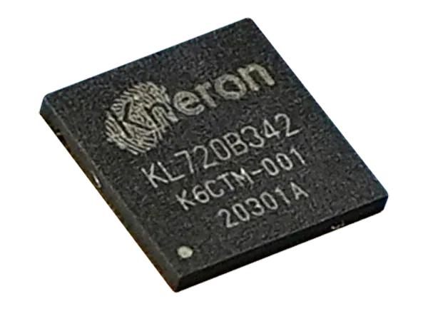
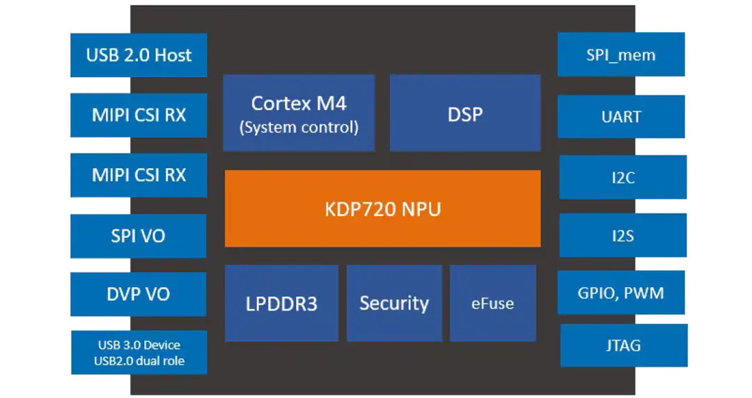
Kneron KL720 AI SoC (System on a Chip) offers an ideal balance of performance, power saving, and cost for hardware makers who are looking to benefit from on-device edge Artificial Intelligence (AI). Powered by Kneron’s Neural Processing Unit (NPU) that accelerates neural network models, the KL720 SoC makes possible endless AI applications for smart devices.
The NPU core is of the KL720 is designed to accelerate major computing layers inside the Convolutional Neural Network (CNN) and Recurrent Neural Network (RNN) to off-load heavy computing from the traditional CPU or GPU structure.
Features Highlights
Low-power design enabled by ARM Cortex M4 CPU
Power to process 4K images, Full HD videos, and 3D sensing for fool-proof facial recognition and to enable innovative gesture control for gaming, shopping kiosks, and more
Ideal for any high-end IP Cams, Smart TVs, AI glasses and headsets, and AIoT Gateways
Power to drive natural language processing (NLP) for translators and AI assistants
All the above and more can be processed at the same on the KL720
Features
NPU
696MHz maximum frequency
GOPS, 1024MAC/cycle peak throughput of 8-bit mode:
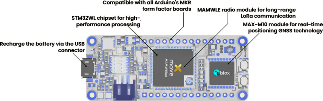
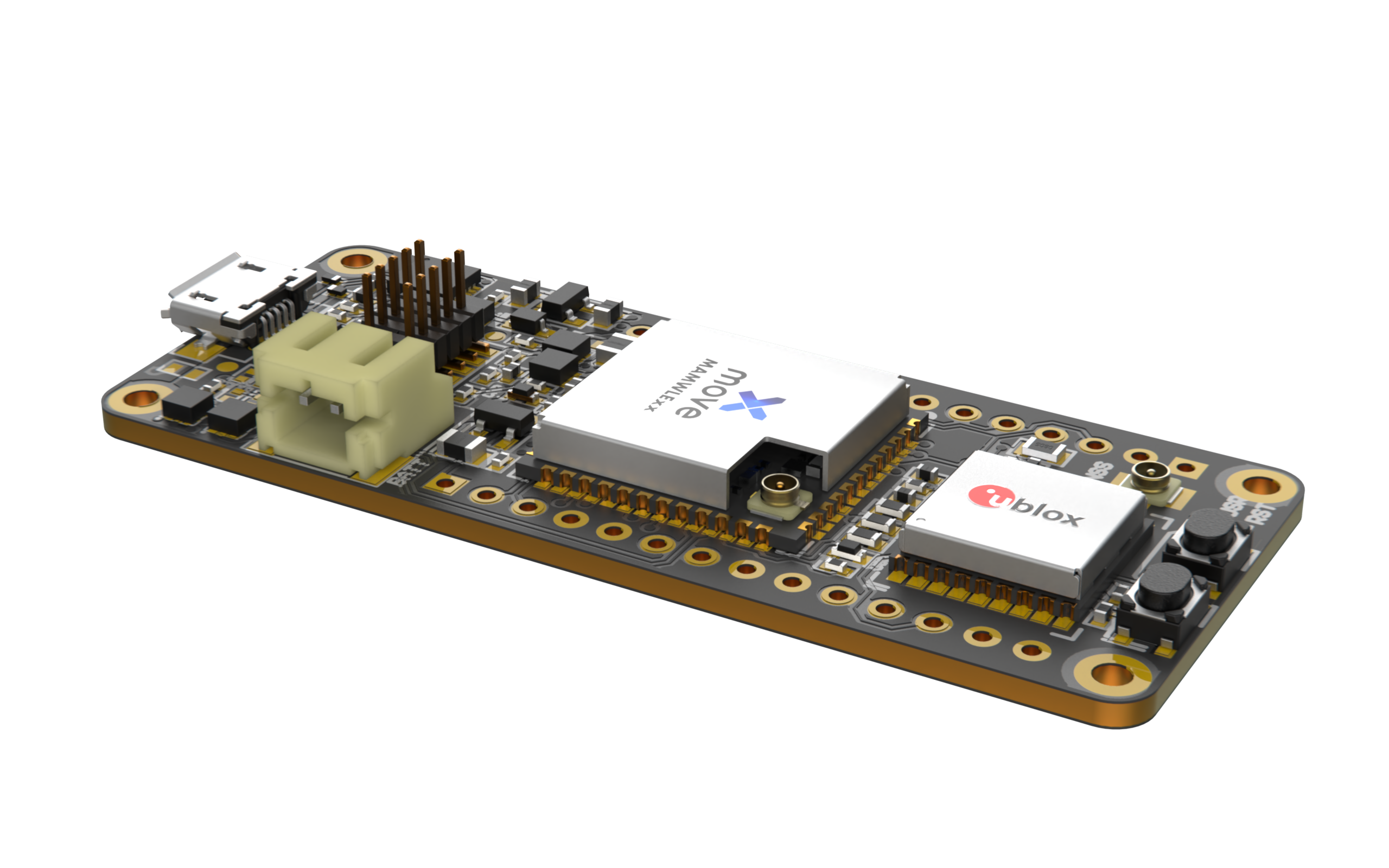
Move-X Cicerone LoRa®/GNSS Board is a high-performance, low-power, Arduino MKR-compatible development board based on the MAMWLE LoRa Module and the u-bloxMAX-M10S GNSS Module. The Cicerone Board delivers best-in-class GNSS, long-range wireless connection, and high-performance MCU processing in a low-power solution for optimal battery life.
The Cicerone Board allows users to build tracking applications worldwide with meter-level accuracy and to communicate long-range, low-power data via LoRaWAN®. The integrated Li-Po charging circuit enables the Cicerone Board to manage battery charging through the USB port.
The Move-X Cicerone LoRa/GNSS Board features a compact 63mm x 25mm form factor and is compatible with all Arduino MKR Shield Boards. These boards all share a common pinout to enable developers to easily add expansions with minimal software changes.
Features
63mm x 25mm PCB
2x push buttons: Reset, User)
2x LEDs: Battery charging status (Red), User (Green)
Headers compatible with Arduino MKR pinout
SWD signals for debugging
RESET, BOOT0
+3.3V output (LDO)
+5V input
+5V output (internally MUXed between USB and +5V input)
VREF output
GNSS module’s UART (allows firmware update)
MAMWLE SPI
I2C shared by LoRa and GNSS module
Up to 22 digital GPIO
Inputs for ADC
PWM outputs
Interfaces
USB micro for UART, RESET/BOOT0 driver, supply input, battery charge @200mA
Connector for single-cell 3.7V Li-Po battery (battery shall include protection circuitry against SC, OD, OC)
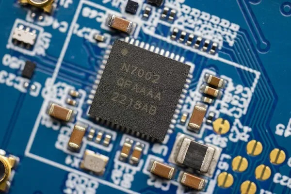
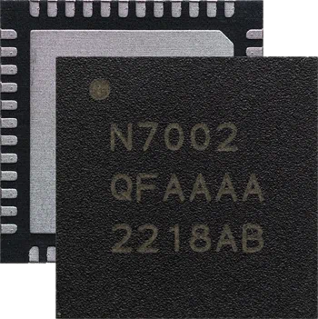
Nordic Semiconductor has announced its entry into the Wi-Fi wireless IoT market with the launch of the nRF7002, an ultra-low power, dual-band Wi-Fi 6 companion IC.
Nordic Semiconductor is now one of just a few companies offering all three of the world’s most popular wireless IoT technologies: Bluetooth, Wi-Fi, and cellular IoT.
The nRF7002 is described by Nordic as a ‘companion IC’ which means it is designed to provide seamless Wi-Fi connectivity and Wi-Fi-based locationing (SSID sniffing of local Wi-Fi hubs) when used alongside Nordic’s existing products. These include the nRF52 and nRF53 Series multiprotocol Systems-on-Chip (SoCs), and nRF91 Series cellular IoT Systems-in-Package (SiPs).
The nRF7002 can also be used in conjunction with non-Nordic host devices.
The launch of the nRF7002 follows Nordic’s 2020 acquisition of the development team, core Wi-Fi expertise, and Wi-Fi IP tech assets of Imagination Technologies Group.
W-Fi forms an integral part of the smart home Matter protocol championed by Apple, Amazon, Google, Samsung, and hundreds of other companies in consumer IoT. By adding Wi-Fi to its product range Nordic will now be able to support all three wireless protocols used in Matter. Namely: Bluetooth LE for commissioning, Thread for low power mesh networking, and Wi-Fi for high-speed wireless applications.
“We were able to bring our first Wi-Fi IC to market very quickly as a result of acquiring an extremely capable Wi-Fi team alongside a portfolio of Wi-Fi assets that team had already developed,” said Nordic CTO/EVP of R&D and Strategy, Svein-Egil Nielsen. “Nordic has also ensured that developing Nordic-based Wi-Fi 6 applications will be as simple as developing any other Nordic wireless IoT application, including using the same development tools and nRF Connect SDK.”
“The new Wi-Fi team’s relentless hard work to enable Nordic to launch its first Wi-Fi product so soon deserves huge recognition,” continued Mike Davis, Nordic’s Wi-Fi Systems & Software Director. “They knew Wi-Fi was the number one missing capability requested by Nordic customers. And they knew Nordic’s customers needed this capability quickly.”
The nRF7002 is supplied in a 6 x 6mm QFN package and is sampling now.
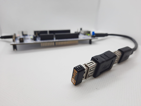
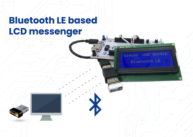
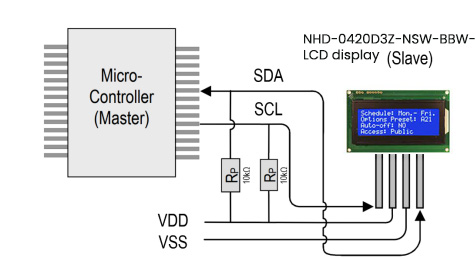
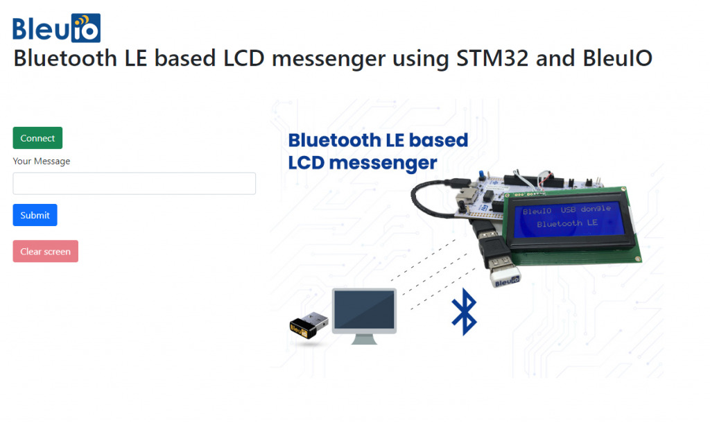
The aim of this project is to send messages via Bluetooth using a web browser or smartphone to an LCD display that is connected to the STM32 board.
1. Introduction
The project is based on STM32 Nucleo-144 which controls LCD display using BleuIO.
For this project, we will need two BleuIO USB dongles, one connected to the Nucleo board and the other to a computer, running the web script.
When the BleuIO Dongle is connected to the Nucleo board’s USB port the STM32 will recognize it and directly start advertising. This allows the Dongle on the computer port to connect with the web script.
With the web script on the computer, we can send messages to the LCD screen connected to STM32 using BleuIO.
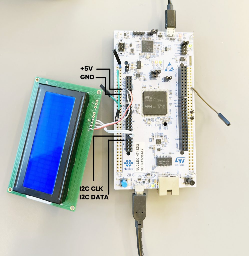
We have used an STM32 Nucleo-144 development board with STM32H743ZI MCU (STM32H743ZI micro mbed-Enabled Development Nucleo-144 series ARM® Cortex®-M7 MCU 32-Bit Embedded Evaluation Board) for this example. This development board has a USB host where we connect the BleuIO dongle.
If you want to use another setup you will have to make sure it support USB Host and beware that the GPIO setup might be different and may need to be reconfigured in the .ioc file.
Either clone the project or download it as a zip file and unzip it, into your STM32CubeIDE workspace.
If you download the project as a zip file you will need to rename the project folder from ‘stm32_bleuio_lcd-master’ to ‘stm32_bleuio_lcd’
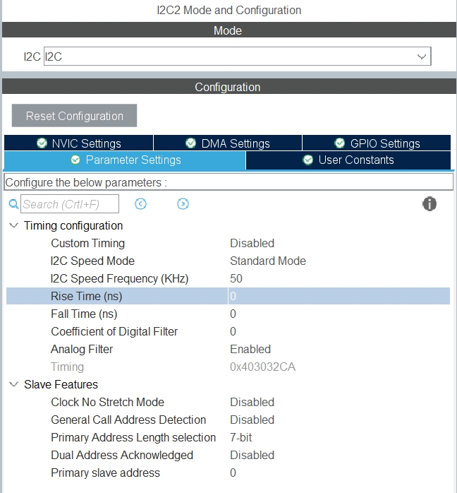
Connect the SDA to PF0 on the Nucleo board and SCL to PF1.
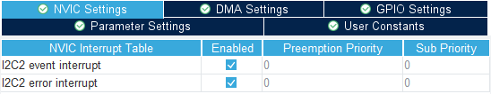
Then setup I2C2 in the STM32Cube ioc file as follows. (Make sure to change the I2C speed frequency to 50 KHz as per LCD display requirements.)
In the USBH_CDC_ReceiveCallback function in USB_HOST\usb_host.c we copy the CDC_RX_Buffer into an external variable called dongle_response that is accessible from the main.c file.
void USBH_CDC_ReceiveCallback(USBH_HandleTypeDef *phost)
{
    if(phost == &hUsbHostFS)
    {
        // Handles the data recived from the USB CDC host, here just printing it out to UART
        rx_size = USBH_CDC_GetLastReceivedDataSize(phost);
    HAL_UART_Transmit(&huart3, CDC_RX_Buffer, rx_size, HAL_MAX_DELAY);

    // Copy buffer to external dongle_response buffer
    strcpy((char *)dongle_response, (char *)CDC_RX_Buffer);

    // Reset buffer and restart the callback function to receive more data
    memset(CDC_RX_Buffer,0,RX_BUFF_SIZE);
    USBH_CDC_Receive(phost, CDC_RX_Buffer, RX_BUFF_SIZE);
    }

    return;
}
In main.c we create a simple interpreter so we can react to the data we are receiving from the dongle.
We put the interpreter function inside the main loop.
/* Infinite loop */
  /* USER CODE BEGIN WHILE */
  while (1)
  {
    /* USER CODE END WHILE */
    MX_USB_HOST_Process();

    /* USER CODE BEGIN 3 */
    // Simple handler for uart input
    handleUartInput(uartStatus);

    // Inteprets the dongle data
    dongle_interpreter(dongle_response);

  // Starts advertising as soon as the Dongle is ready.
  if(!isAdvertising && !isConnected && isBleuIOReady)
  {
    HAL_Delay(200);
    writeToDongle((uint8_t*)DONGLE_CMD_AT_ADVSTART);
    isAdvertising = true;
  }
  }
  /* USER CODE END 3 */
A board with an STM32 Microcontroller with a USB port. (A Nucleo-144 development board: NUCLEO-H743ZI2, was used developing this example. (https://www.st.com/en/evaluation-tools/nucleo-h743zi.html)
To connect the dongle to the Nucleo board a “USB A to Micro USB B”-cable with a USB A female-to-female adapter can be used.)
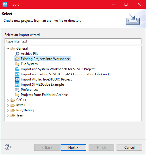
Then choose General>Existing Projects into Workspace then click ‘Next >’
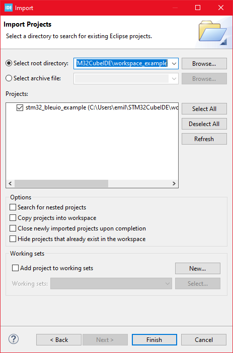
Make sure you’ve chosen your workspace in ‘Select root directory:’
You should see the project “stm32_bleuio_SHT85_example”, check it, and click ‘Finish’.
Running the example
Upload the code to STM32 and run the example. The USB dongle connected to STM32 will start advertising automatically.
Send Messages to the LCD screen from a web browser
Connect the BleuIO dongle to the computer. Run the web script to connect to the other BleuIO dongle on the STM32. Now you can send messages to the LCD screen.
Create a simple Html file called index.html which will serve as the frontend of the script. This Html file contains some buttons that help connect and read advertised data from the remote dongle, which is connected to stm32.
Create a js file called script.js and include it at the bottom of the Html file. This js file uses the BleuIO js library to write AT commands and communicate with the other dongle.
import * as my_dongle from 'bleuio'
const dongleToConnect='[0]40:48:FD:E5:2F:17'
document.getElementById('connect').addEventListener('click', function(){
  my_dongle.at_connect()
  document.getElementById("clearScreen").disabled=false;
  document.getElementById("connect").disabled=true;
  document.getElementById("sendMsgForm").hidden=false;
})

document.getElementById("sendMsgForm").addEventListener("submit", function(event){
    event.preventDefault()
    console.log('here')


    my_dongle.ati().then((data)=>{
        //make central if not
        if(JSON.stringify(data).includes("Peripheral")){
            console.log('peripheral')
            my_dongle.at_central().then((x)=>{
                console.log('central now')
            })
        }
    })
    .then(()=>{
        // connect to dongle
        my_dongle.at_getconn().then((y)=>{
            if(JSON.stringify(y).includes(dongleToConnect)){
                console.log('already connected')
            }else{
                my_dongle.at_gapconnect(dongleToConnect).then(()=>{
                    console.log('connected successfully')
                })
            }
        })
        .then(()=>{
            var theVal = "L=1 " + document.getElementById('msgToSend').value;
            console.log('Message Send 1 '+theVal)
            // send command to show data
            my_dongle.at_spssend(theVal).then(()=>{
                console.log('Message Send '+theVal)
            })
        })

    })
  });


document.getElementById('clearScreen').addEventListener('click', function(){
    my_dongle.ati().then((data)=>{
        //make central if not
        if(JSON.stringify(data).includes("Peripheral")){
            console.log('peripheral')
            my_dongle.at_central().then((x)=>{
                console.log('central now')
            })
        }
    })
    .then(()=>{
        // connect to dongle
        my_dongle.at_getconn().then((y)=>{
            if(JSON.stringify(y).includes(dongleToConnect)){
                console.log('already connected')
            }else{
                my_dongle.at_gapconnect(dongleToConnect).then(()=>{
                    console.log('connected successfully')
                })
            }
        })
        .then(()=>{
            // send command to clear the screen
            my_dongle.at_spssend('L=0').then(()=>{
                console.log('Screen Cleared')
            })
        })

    })
})
The script has a button to connect to the COM port on the computer. There is a text field where you can write your message. Your messages will be displayed on an LCD screen connected to the STM32 board.
To connect to the BleuIO dongle on the STM32, make sure the STM32 is powered up and a BleuIO dongle is connected to it.
Get the MAC address
Follow the steps to get the MAC address of the dongle that is connected to STM32:
Open this site https://bleuio.com/web_terminal.html and click connect to dongle.
Select the appropriate port to connect.
Once it says connected, type ATI. This will show dongle information and current status.
If the dongle is on the peripheral role, set it to central by typing AT+CENTRAL
Now do a gap scan by typing AT+GAPSCAN
Once you see your dongle on the list, stop the scan by pressing control+c
Copy the ID and paste it into the script (script.js) line #2
Run the web script
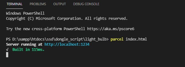
You will need a web bundler. You can use parcel.js
Once parcel js is installed, go to the root directory of the web script and type “parcel index.html”. This will start your development environment.
Open the script on a browser. For this example, we opened http://localhost:1234
You can easily connect to the dongle and send your message to the LCD screen. The response will show on the browser console screen.
AAEON, a global leader in industrial computing, has introduced the world to the next generation of single board computers with the release of the EPIC-TGH7, which holds the distinction of being the first board of its kind to host Intel® 11th Generation Xeon®/Core™ processors.
With such an advanced processor package, the EPIC-TGH7 offers 8 cores and 16 threads to increase processing speed and power for intensive, high-end computing. However, this advancement has not sacrificed power-efficiency, with the EPIC-TGH7 providing up to 45W with Xeon®-level performance.
Hosting up to 8 USB ports, dual LAN ports, and a PCIe[x8] slot; the EPIC-TGH7 enables PCIe4.0 speeds of up to 16GT/s, despite retaining the same EPIC board form factor measuring just 4.53″ x 6.50″ (115mm x 165mm).
AAEON believes this combination of I/O density and high-speed expansion will be particularly applicable to healthcare imaging and military defense applications, with the board being able to accommodate the advanced graphics required for such uses.
In addition to healthcare imaging and military defense applications, the EPIC-TGH7 lends itself to use in digital signage, providing 4 simultaneous displays via an I/O featuring HDMI, VGA, Dual Channel 24/48bit LVDS, and DP ports. Such a myriad of options is designed to give users a diverse selection of display configurations to suit their project needs.
For more information regarding the EPIC-TGH7, please visit its product page, or contact an AAEON sales representative directly.
One of the definitions of ‘signal‘ in the Merriam-Webster dictionary is: “A detectable physical quantity or impulse (as a voltage, current, or magnetic field strength) by which messages or information can be transmitted from a source to a destination.”
A signal is simply a function, i.e., a mathematical relationship in which the values of a single dependent variable are determined by the values of independent variables. Generally, the independent variables could be time (e.g. in speech signals), space (e.g. in image data), and so on. Also, dependent variables could be like the voltage of a transistor’s collector, light intensity, etc. We are usually interested in using a physical variable not just at a single time, but rather at a set of times. In this case, the signal is a function of time, say f(t). For example, f(t) might denote voltage levels in some instants of time.
In electronics, a signal is an electrical quantity or effect, such as voltage, current, or electromagnetic fields that can be varied in such a way to convey information. The information can be recorded, conveyed, displayed, or manipulated. Electrical effects which do not convey usefully or wanted information are called noise. For this reason, one of the main criteria for the performance of a system is to measure its signal-to-noise power ratio (SNR).
There are many examples of signals including temperature, pressure, sound waves, such as speech and music, electromagnetic waves, such as radio signals, and biomedical signals, such as the electroencephalogram (EEG) and electrocardiogram (ECG).
Obviously, most of the signals are not originally in the electrical form; like temperature variations or mechanical displacement. A transducer is a device that converts a signal from one form of energy into another. For example, microphones and speakers alter pressure variations into electric voltages and vice versa. Transducers that produce electrical signals for applications in the areas of measurement and control are usually known as sensors. Examples of sensors are solar cells which convert light energy into electric voltage or thermistors which transform heat energy into electrical resistance.
In practice, the amplitude of most signals varies with time. In electronics and related fields, the waveform of a signal is the shape of its amplitude as a function of time, i.e., by plotting the amplitude on the vertical axis (y) and time on the horizontal axis (x). The waveform of an electrical signal can be visualized in an oscilloscope or any other device that can capture and plot its values at various times, with a suitable scale in the time and magnitude axes.
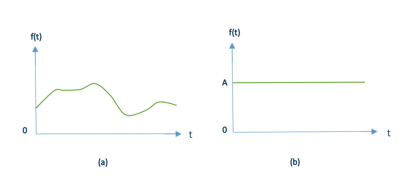
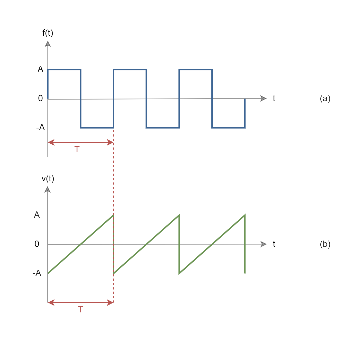
An electrical signal whose amplitude does not change with time over the duration of its measurement is called a direct current (DC) signal. Although most practical signals are time-varying. If the shape of the corresponding plot happens to be a sine wave, then the signal is called a sinusoidal signal. Sine waves can be considered to be the building blocks of many other signals. Figure1 shows examples of signal waveforms as functions of time.
Figure 1: Waveforms of 2 types of signals including (a) a general time-varying signal and (b) a constant or DC signal with amplitude A.
Signal Processing
Signal processing techniques focus on analyzing, modifying, and synthesizing signals such as sound, images, or scientific measurements. Examples of systems that manipulate signals by these techniques are speech recognition, video streaming, cellular networks, and medical scans such as MRI.
Signals are processed for a variety of reasons, such as to remove unwanted noise, correct distortions, to make them suitable for transmission, or extract certain meaningful information. Filtering is one of the most basic and important signal processing techniques; like designing signal filters based on using op-amps and discrete components of resistors, capacitors, and inductors.
Historically, signal processing was performed entirely in the analog domain. Since the late 20th century, signal processing has necessarily transitioned to the digital domain.
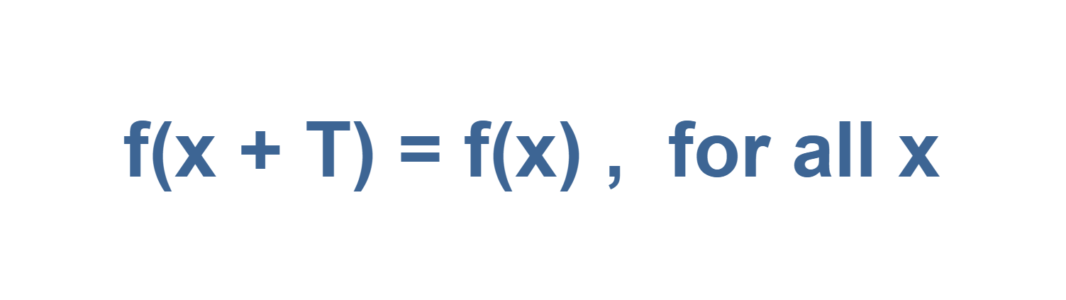
A signal is said to be periodic in time if its amplitude values are repeated after equal intervals of time. A period is defined as the amount of time (mostly expressed in seconds) required to complete one full cycle. This means a periodic signal repeats its pattern over sequential periods. Formally, a function f(x) is periodic with period ‘T’ (where T> 0) if:
Equation 1: Definition of a periodic function
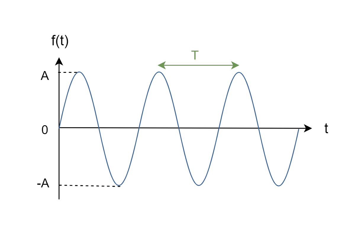
The most famous periodic signals are trigonometric functions, like sine and cosine waves. Figure2 shows a periodic sine wave, f(t), with period ‘T’ which is the time interval between 2 positive peaks.
Figure 2: A periodic sinusoidal waveform with period T
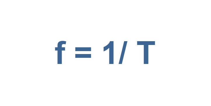
The frequency of a periodic function is the number of complete cycles that occur per second. Frequency can be defined in terms of the period, as follows:
Equation 2: Definition of frequency
Frequency has the units of hertz (Hz) or ‘cycle per second.
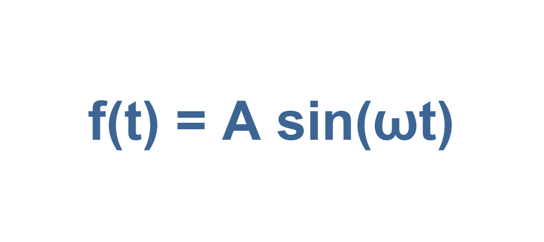
This sinusoidal waveform can be defined by the function in Equation 3:
Equation 3: Definition of a sinusoidal waveform
Here ‘A’ is the maximum amplitude or the peak value of the signal f(t).
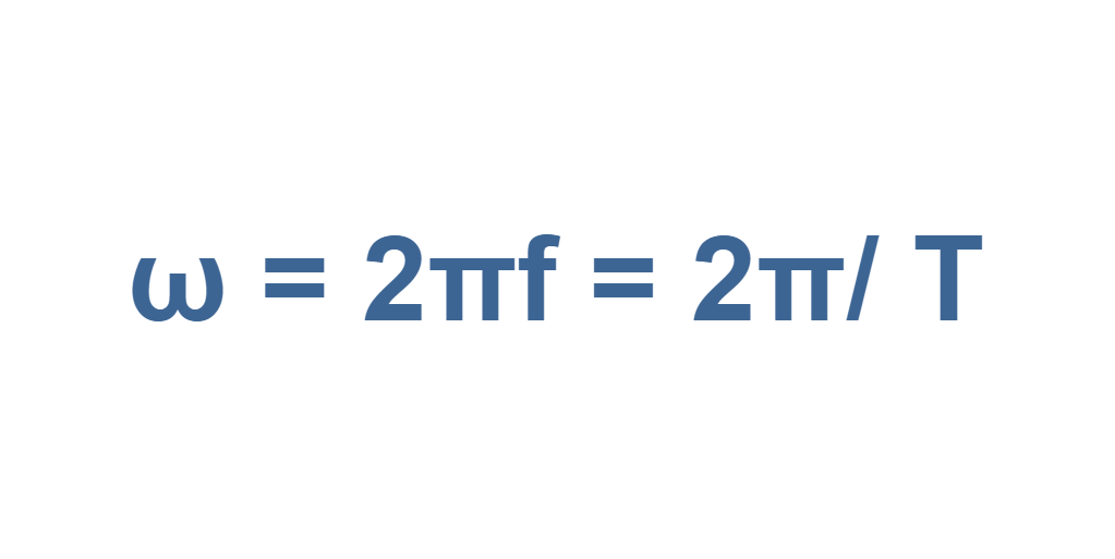
The angular (or rotational) frequency (ω) measures angular displacement per unit of time. Its units are degrees (or radians) per second. It is defined in Equation 4:
Equation 4: definition of angular frequency
Equation 4 implies that f(t) repeats itself for all time, with a repetition period T (= 2π/ ω).
Because, the alternating current (AC) is defined as an electric current whose direction is reversed periodically and its magnitude is changed continuously with time, periodic signals are mostly called AC signals. The usual waveform of AC signals in most electric circuits are sine waves, whose positive half-period corresponds with the positive direction of the current and the negative half-period corresponds with the negative direction of it.
Obviously, no real signal goes on forever, but Equation (3) could be a reasonable model for a sinusoidal waveform that lasts a long time compared to the period of T. Thus, AC steady-state circuit analysis depends upon the assumption of an eternal sinusoid.
Figure 3 illustrates waveforms of some other famous periodic signals.
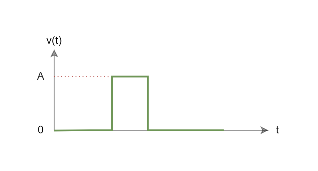
Any signal that is not periodic is called aperiodic or non-periodic. A non-periodic function does not remain self-similar for multiples of its period. Most of the real Signals that carry information, such as speech, music, or video, do not repeat endlessly. The waveform of Figure 1 (a) is an example of a non-periodic signal. Figure 4 also shows a single rectangular pulse shape wave used in radars as another example of a non-periodic waveform.
Figure 4: A single rectangular pulse shape waveform
Time Domain and Frequency Domain Representation
Since time flows continuously and irreversibly, it is natural to describe sequential signal values as given by a time arrangement. By measuring amplitude values of signals at different time instants, we can monitor how the signal has changed with the passage of time. A plot of these results is known as the time-domain representation of the signal. The above-mentioned waveforms in figures 1 to 4 were all examples of representation in the time domain.
For better analysis of signal characteristics, we might be interested in measuring the quantity as a function of frequency rather than time. There are certain applications that frequency-domain representation that is very useful. This representation is also known as the spectrum of the signal.
We can study the spectrum to determine which frequencies are present in the input signal and which are present or missing in the output, which means the frequency-domain signal analysis. Then, it is possible to add or subtract frequencies to the original signal, i.e., the frequency-domain signal processing method.
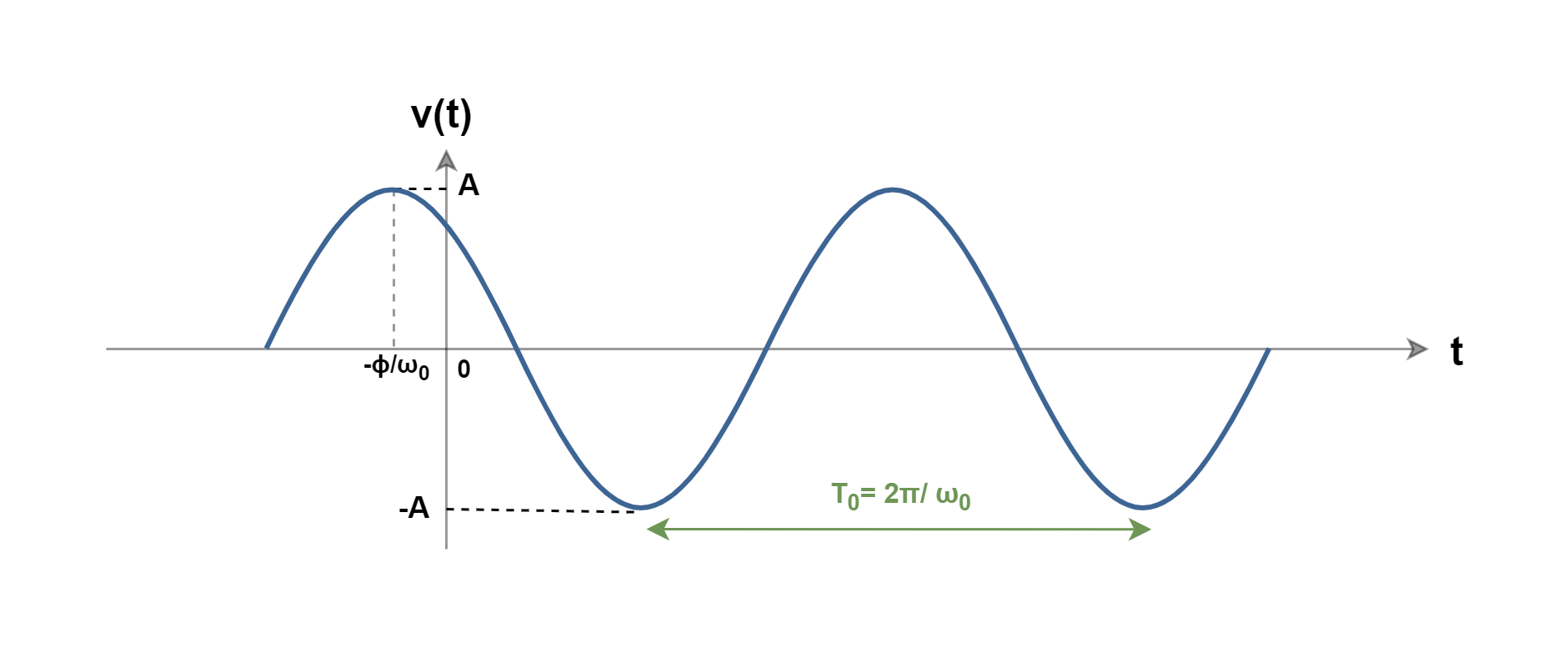
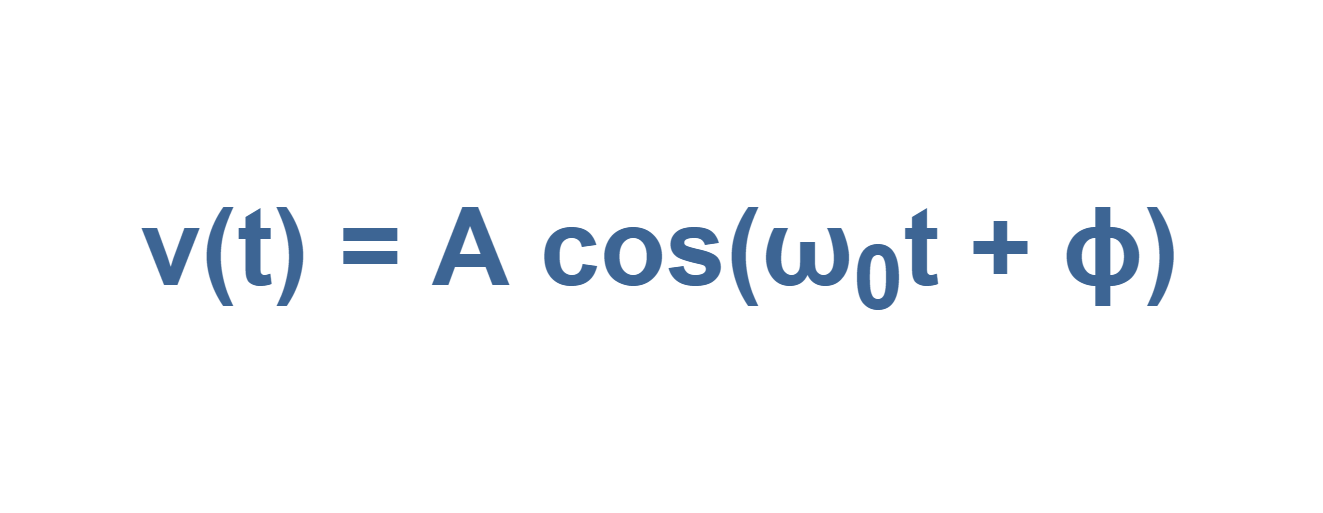
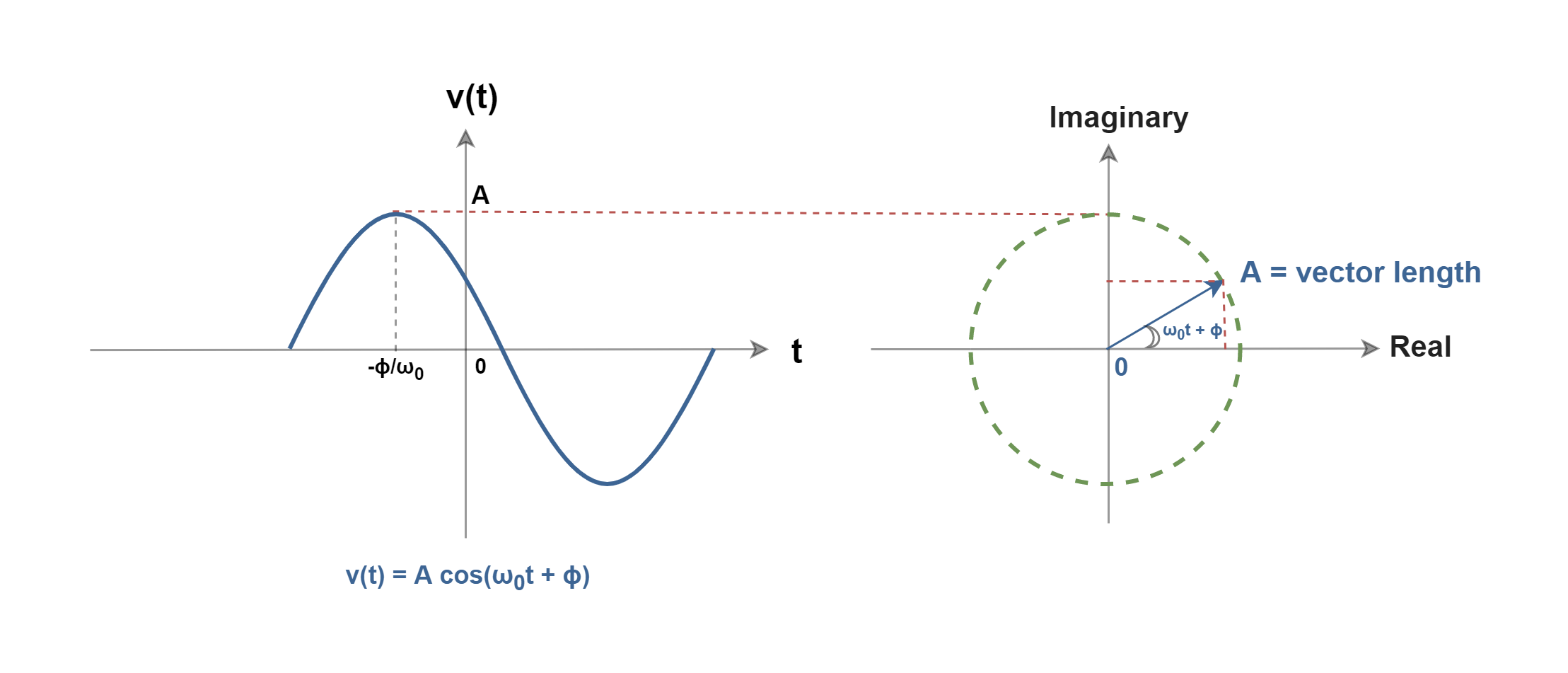
As a general description, consider an example of the familiar AC waveform as a cosine function of v(t) which is plotted in Figure 5.
Figure 5: A sinusoidal waveform with a phase shift from the origin
By convention, we can describe the cosine function by a general expression of Equation 5:
Equation 5: A cosine function
where ‘A’ is the peak of the signal and the phase angleϕ represents the fact that the peak of the waveform has been shifted away from the time origin and occurs at (t = -ϕ/ω0). In Equation 5 both the arguments (ω0t) and the phase angle (ϕ) can be in radians or degrees.
Sinusoids are easily expressed in terms of phasors. A phasor is a complex representation of the magnitude and phase of a sinusoid, regardless of time dependency. A phasor can also be defined as a vector on the surface of complex numbers with the real and the imaginary axes. We can imagine that in a complex plane, as time increases, the phasor rotates on a circle of radius ‘A’ at an angular velocity ω0 (= 2πf0) in the counterclockwise direction. Figure 6 depicts the concept of angular frequency and phasor.
Figure 6: Phasor diagram of a sinusoidal signal
The concept of ‘complex numbers’ is out of the scope of this article and we just needed it to achieve the main idea. You could refer to the attached link to get more information.
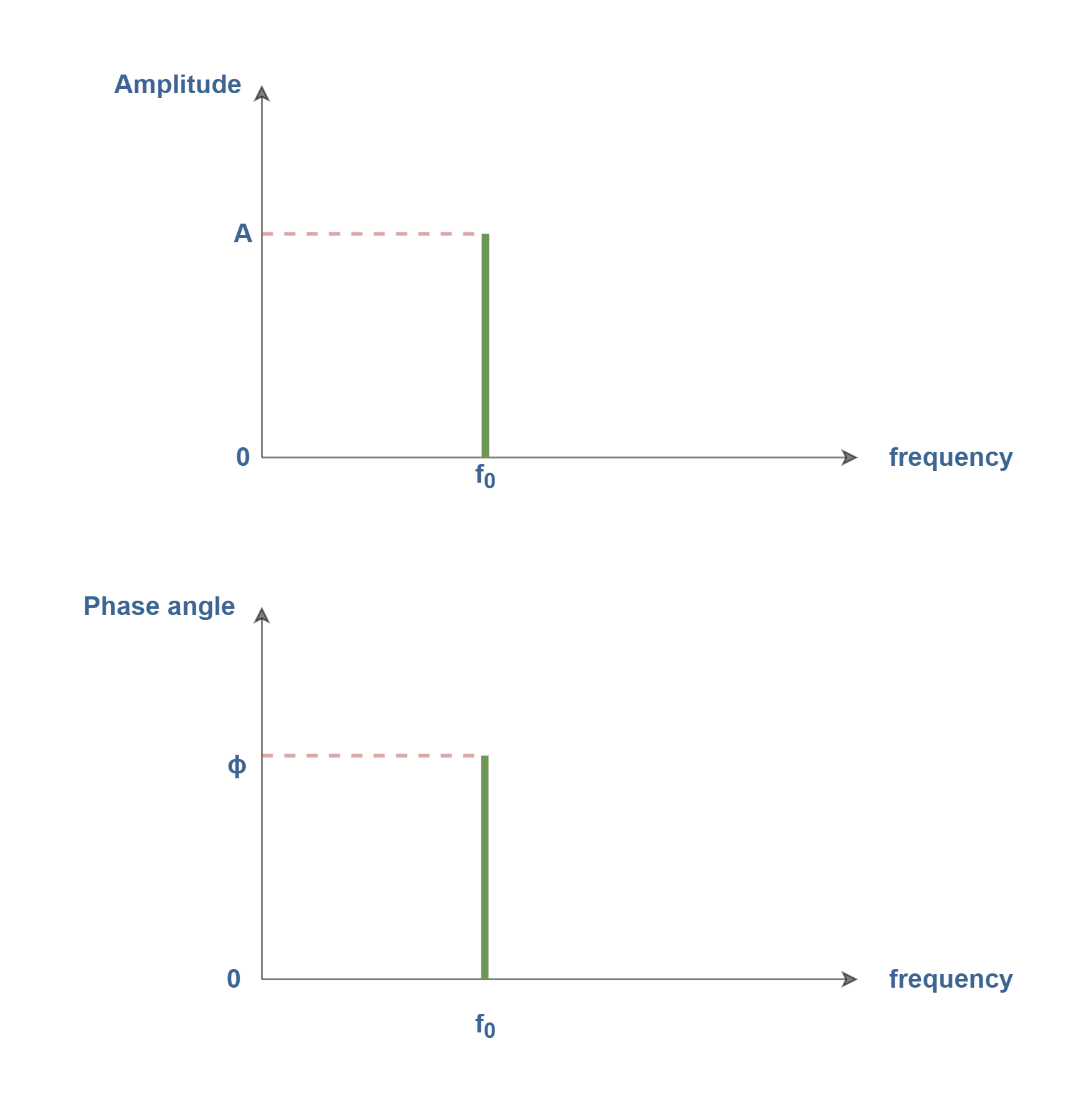
Only three parameters can completely specify a phasor: amplitude,phase angle, and angular frequency. To describe the same phasor in the frequency domain, we must associate the corresponding amplitude and phase with the particular frequency f0. By applying the phasor concept, a real function of v(t) in the time domain is converted to a complex number V(ω) in the frequency domain.
A suitable frequency-domain description would be the line spectrum shown in Figure 7, which consists of two plots: amplitude (of phasors) versus frequency and phase angle (of phasors) versus frequency.
Figure 7: line spectrum representation of the sinusoidal signal
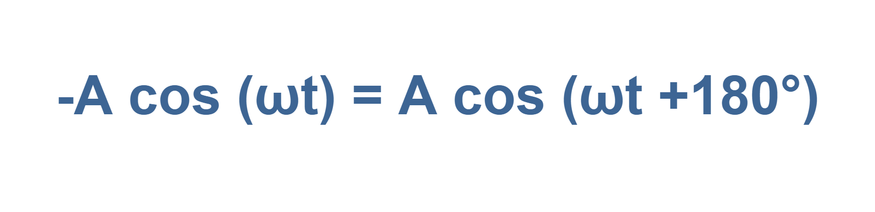
In this line spectra illustration, we regard amplitude as always being a positive quantity. When negative signs appear, they must be absorbed in the phase angle using the next equation:
Equation 6: Conversion of amplitude polarity to phase angle
The amplitude spectrum essentially conveys more information than the phase spectrum and it displays the signal’s frequency content, i.e., the amplitude spectrum tells us what frequencies are present and in what proportion. Drawings like Figure 7, called one-sided or positive-frequency line spectra, can be constructed for any linear combination of sinusoids.
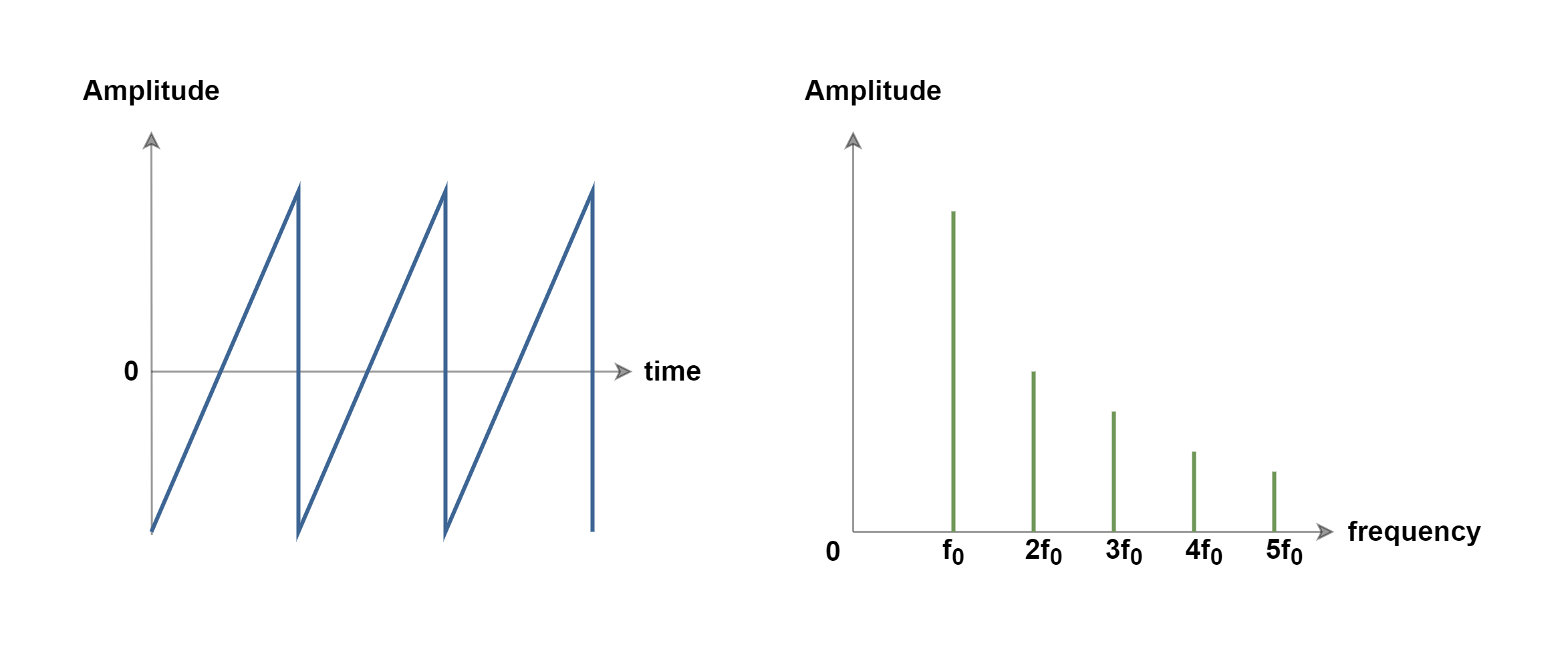
Figure 8 shows the illustration of a sawtooth wave shape signal in time and frequency domains. In both illustrations, the y-axis represents the amplitude of the signal. Each of them presents the same phenomenon from different viewpoints.
Figure 8: Time-domain versus frequency-domain representations of a sawtooth signal (not on a precise scale)
In Figure 8, the frequency-domain graph clearly shows that a sawtooth wave is a combination of many sine waves (with a line spectrum for each wave), which are all harmonics of the main sine wave with a fundamental frequency of f0. As the frequency of harmonics increases, the corresponding amplitude of line spectra decreases.
Representing the time-domain waveform in Figure 8 could be similar to displaying a signal on an electronic oscilloscope measurement device. On the other hand, looking from the frequency-domain viewpoint in Figure 8 is similar to monitoring the signal on a spectrum analyzer device which can show us information about the amplitude or power of frequency components.
Types of Signals: Continuous and Discrete
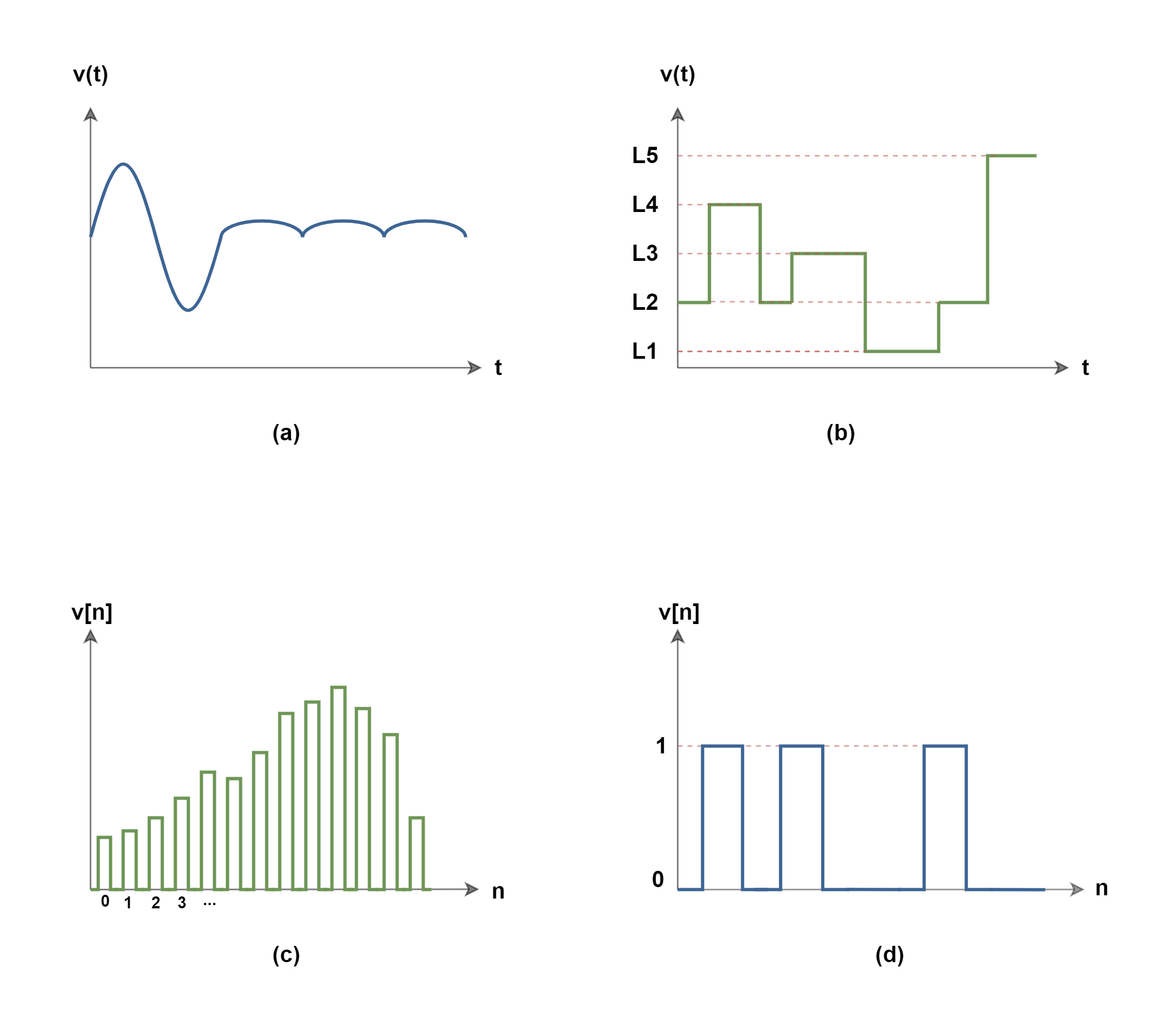
A continuous-time signal is a signal defined over a continuous range of time and its amplitude may have a continuous range of values (analog signal) or only a finite number of distinct values (quantized signal). The distinct values are called quantized values and they can be changed only by a set of distinct steps of magnitude.
Most of the signals naturally occurring in the world are analog and they provide a continuous stream of information on the physical quantity they represent. The main characteristics of analog signals are amplitude, frequency, and phase. The best example of an analog signal is a human’s voice.
A discrete-time signal is a signal defined only at discrete instants of time i.e. the independent variable of time (t) has been quantized. In a discrete-time signal, if the amplitude has a continuous range of values, the signal is called a sampled signal. In this case, if the amplitude contains a set of discrete values, the signal is usually called a digital signal.
In past decades, analog computers employed physical quantities that were approximations of continuous representations of signals. While discrete representations of both time and amplitude are necessary for digital computers in present decades.
If we consider both important variables of time and amplitude, which are essential to represent any type of signal, the categories can be expanded to 4 items:
(a) continuous-time with continuous amplitude (analog signal)
(b) continuous-time with discrete amplitude (quantized signal)
(c) discrete-time with continuous amplitude (sampled signal)
(d) discrete-time with discrete amplitude (discrete/digital signal)
Figure 9 shows an example for each of the categories. It is worth mentioning that in the case of discretization of signal in time, the variable of time (t) is usually replaced by the number of time intervals between amplitude samples and it is denoted by ‘n’.
Figure 9: 4 categories of signals from (a) to (d)
Summary
The term analog signal processing describes a body of techniques that can be implemented to process analog (or real-world) signals.
This includes the theory and application of filtering, coding, transmitting, estimating, detecting, analyzing, and reproducing analog signals.
The frequency f is in units of Hertz (abbreviated Hz) which is sec-1, or often called cycles per second.
ω is also the frequency in terms of radians/sec units and is known as radial or circular frequency. f and ω are related by ω = 2πf.
This is very useful in many applications to find the behavior of the signal in terms of time units. When we can monitor how the signal has changed with the passage of time, we call this the time-domain description of a signal.
A frequency-domain description uses some set of sinusoidal signals as a basis for describing a signal.
The observer can look at the amplitude variations of the signal from the time-domain or frequency-domain point of view.
The term periodic signal is usually applied to periodically varying voltages, currents, or electromagnetic fields.
The opposite of a periodic signal is an aperiodic signal. An aperiodic function never repeats.
Frequency-domain signal descriptions decompose the source signals into sinusoidal components. The frequency of the sinusoid that most closely matches the signal is the principal frequency component of the signal.
Non-periodic signals can also be represented in the frequency domain.
Signals can be categorized in continuous or discrete types, in amplitude or time.
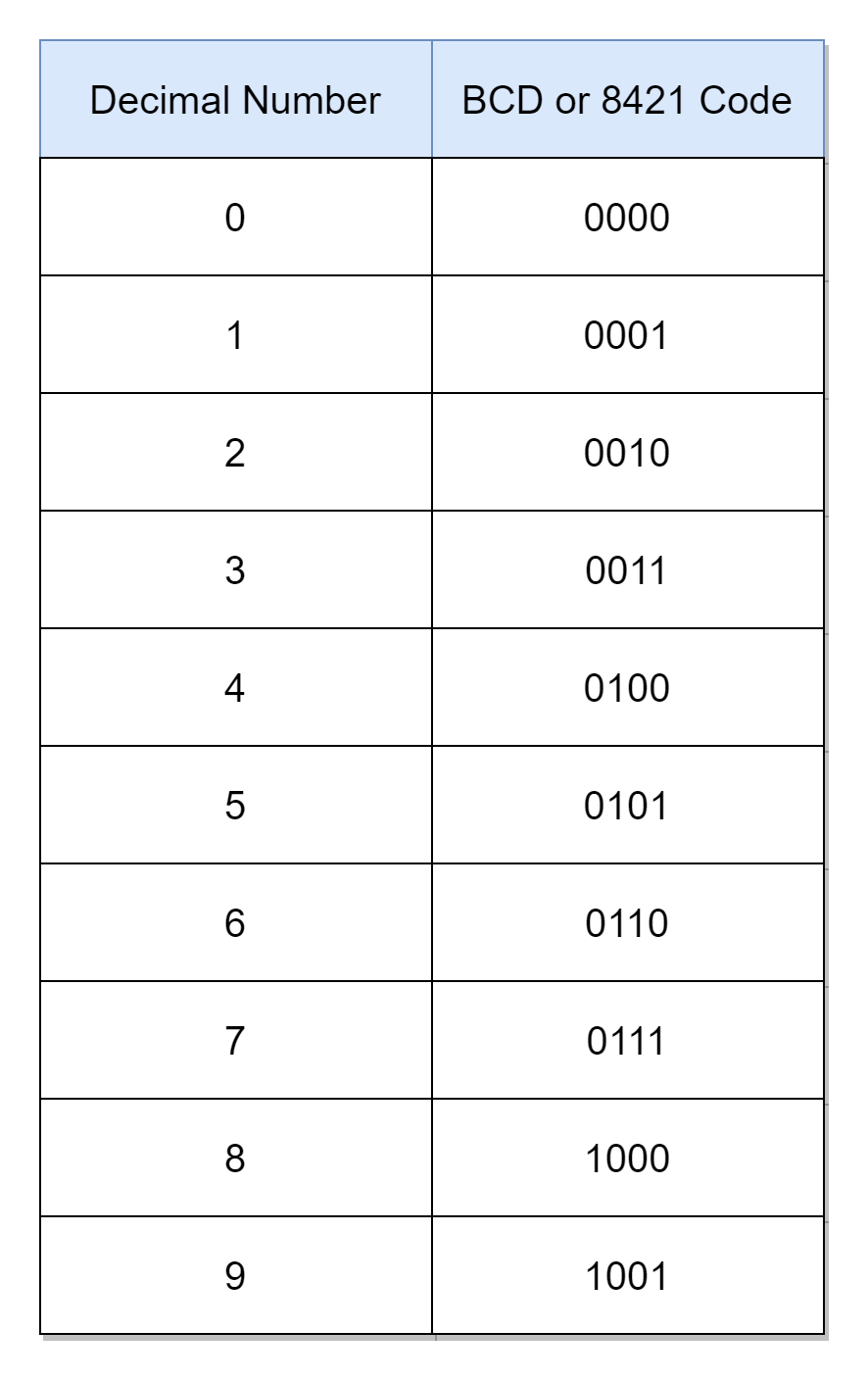
The Binary Coded Decimal is a 4-bit binary number coded to represent specifically a decimal number. The “coded” refers to the process of assigning a specific or unique binary code to a particular decimal number. In the Binary Coded Decimal or shortly BCD, the decimal numbers from “0” to “9” are binary coded. The binary code representing each decimal number is called a Binary Coded Decimal. The Binary Coded Decimals are used in digital systems for displaying decimal values, mainly.
The decimal numbers use a base-10 numbering system and, as such, there are a total of ten (10) decimal numbers from “0” to “9”. Likewise, binary numbers use a base-2 numbering system. In order to code “0” to “9” decimal numbers in binary, ten (10) unique combinations of binary numbers are required, each representing a single decimal number. The number of combinations that can be produced by binary digits or bits (n) is given by 2n. The representation of ten (10) decimal numbers requires a binary code having at least four (4) binary digits or bits. The Binary Coded Decimal uses the minimalist bits’ option of four (4) to represent decimal numbers.
The famous Hexadecimal numbering system also uses the four (4) bits to represent equivalent binary numbers. The hexadecimal number uses a base-16 numbering system and there is a total of sixteen (16) hexadecimal numbers. The Binary Coded Decimals are similar to Hexadecimal numbers. However, Binary Coded Decimal (BCD) encoding uses only “0” to “9” numbers, and the rest of the numbers i.e. from “A” to “F” or from “10” to “15” are not required. The hexadecimal numbers from “0” to “9” are similar to the binary coded decimals, “0” to “9”, respectively.
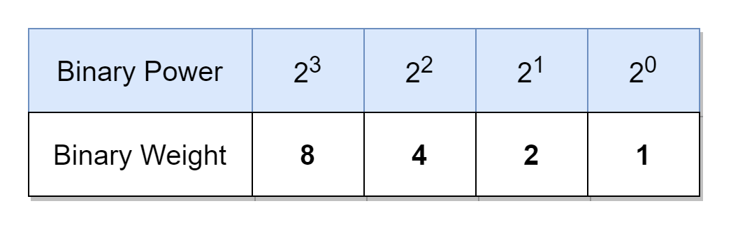
The usage of Binary Coded Decimals to represent decimal numbers has many advantages in digital systems and, amongst these, the main advantage is the ease of conversion from and to decimals. However, there is a wastage of six (6) numbers from “A” to “F” as discussed above. In Binary Coded Decimal, each decimal digit is represented by a four (4) bit binary number (BCD), and each decimal digit can be represented by a weighted sum of binary values. It is known from previous articles, that the weight of a decimal digit, from right to left, increases by 10 times, whereas, of a binary digit (bit) by 2 times. In four-bit BCD, the first, second, third, and fourth digit has a weight of 20 = 1, 21 = 2, 22 = 4, and 23 = 8, respectively. In the following table, the binary power or weight of each BCD bit is shown.
Using the above table, the weighted sum of bits of “0000” to “1001” binary numbers equalizes to “0” to “9” decimal numbers, respectively. Starting from the right, the four bits of BCD give a weight of 8, 4, 2, and 1, respectively. The weights (8, 4, 2, and 1) of a BCD sum up to constitute a decimal number. Due to this reason, a BCD is also called an 8421 code as it represents a relevant decimal number in a 4-bit format.
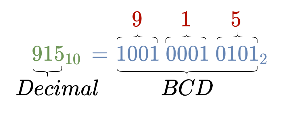
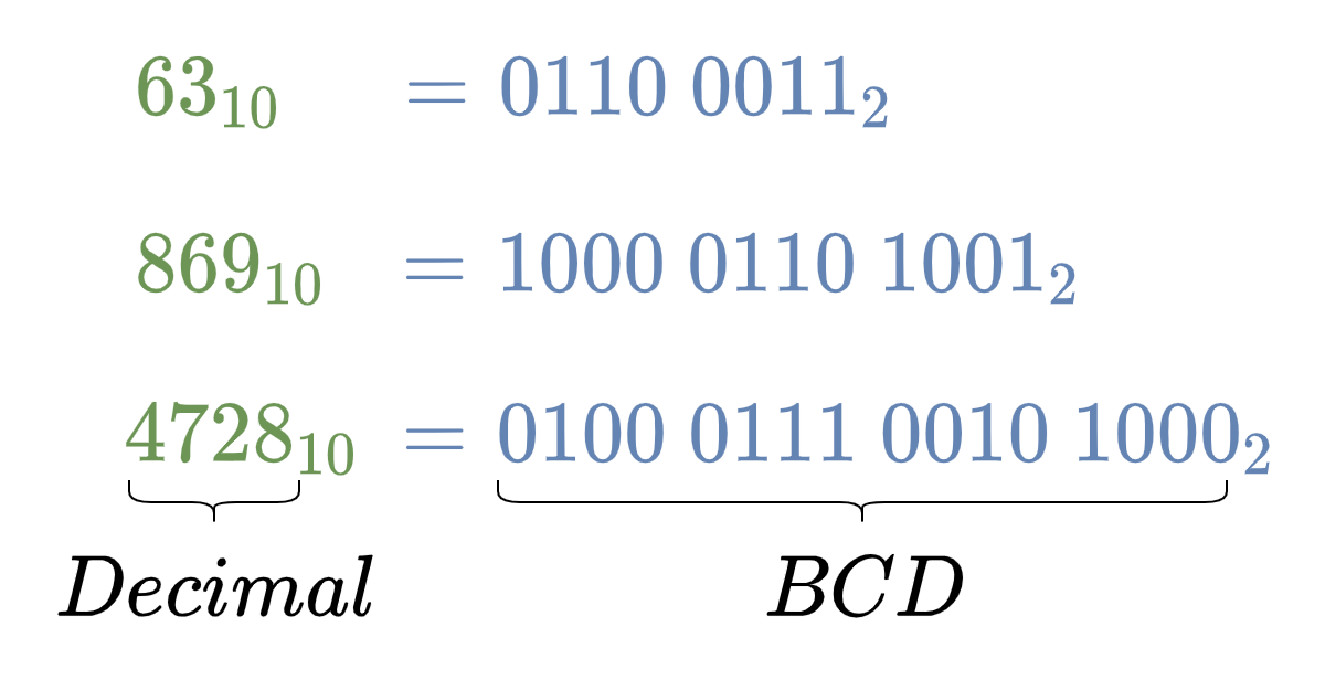
The conversion of a decimal number, consisting of multiple decimal digits, requires obtaining an equivalent BCD for each decimal digit. For example, consider a decimal number of 91510, having three decimal digits i.e. “9”, “1”, and “5”. These decimal digits “9”, “1”, and “5” have equivalent binary coded decimals “1001”, “0001”, and “0101”, respectively. The combination of these binary coded decimals is the equivalent of 91510 in BCD as given below.
The following table lists each decimal number against their respective binary coded decimal (BCD). The BCD or 8421 code is unique for “0” to “9” digits and for numbers greater than “9” such as “10”, “11”, and “12” etc. each decimal digit is given the respective unique 8421 code, separately. For example, the “10” would make up an 8421 code of “0001 0000” where “0001” and “0000” are unique 8421 codes of “1” and “0”, respectively.
Decimal to BCD Conversion
There are multiple methods to obtain the BCD or 8421 code of a decimal number. Each method requires the processing of each decimal digit, separately, not the whole decimal number. First, and the easiest, way is to memorize these ten (10) BCD codes or lookup the BCD truth table for each decimal digit and find the respective BCD/ 8421 code. The second method would require the application of decimal to binary conversion on each (single) decimal digit i.e. repeated-division-by-2. The third method is to split each decimal digit into weights of bits summing up to desired decimal digit. The weighted binary digits form the equivalent BCD/ 8421 code. A few examples of decimal to equivalent BCD conversions are given below.
Decimal to BCD Conversion Examples
The decimal numbers: 6310, 86910, and 472810 are converted into their equivalent BCD numbers by use of the above-given BCD truth table.
BCD to Decimal Conversion
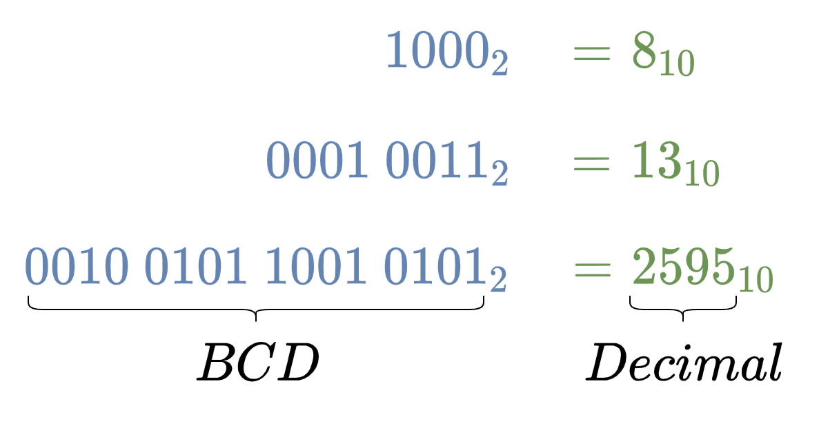
As each decimal digit is represented by a 4-bit BCD and, therefore, it is necessary to split the given binary number into groups of 4-bits. The 4-bit groups are formed from the least significant side (rightmost) to the most significant side (leftmost). Eventually, leading to the formation of the last 4-bit group which may require additional significant zero(s) to complete the 4-bit group. Each 4-bit group represents the respective BCD or 8421 code of that decimal digit. Using the above BCD truth table, equivalent decimal digits against respective BCD/ 8421 codes are obtained. The combination of decimal digits ultimately gives the representation of the desired decimal number. In the following examples, the BCD to decimal conversion is carried out to explain the conversion process.
BCD to Decimal Conversion Examples
The binary numbers: 10002, 100112, and 100101100101012 are converted into their equivalent decimal numbers by splitting into 4-bit groups of 8421 (BCD) codes and then finding equivalent decimal numbers against respective 8421 (BCD) codes using the above given BCD truth table.
The Binary Coded Decimal is a mere representation of a single decimal digit and a decimal number represented by BCD encoding is not the actual binary equivalent of that decimal number. For example, the BCD equivalent of 6310 is 011000112, whereas, the pure binary equivalent of 6310 is 001111112. The BCD representation of decimals is useful for displaying decimal values etc. but is not an efficient way of storing data and for performing arithmetic operations. The storage using BCD encoding would require an additional bit(s) compared to its equivalent true binary number. It is because of discarding six (6) binary numbers out of sixteen (16) as described above. For example, the representation of a three-digit decimal number requires 12-bits in BCD and, contrary to this, a 10-bit binary number can accommodate a decimal number up to “1024”. Moreover, BCD encoded binary numbers are not suitable for arithmetic operations. Consider a simple example of the addition of two BCD binary numbers which generates a carry bit, the addition of this carry bit to a BCD number of “1001” or “9” would lead to an invalid BCD code of “1010”. The solution requires conversion from binary to decimal i.e. 1010 and then reverting to BCD equivalent i.e. “0001 0000”. However, it is more suitable and convenient to convert BCD encoded numbers to pure binary numbers before performing any arithmetic operations.
Binary Coded Decimal Decoder IC
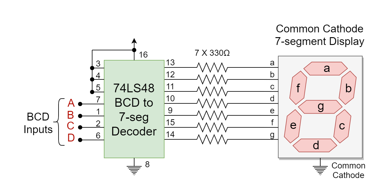
The usage of Binary Coded Decimal is useful in applications requiring the display of information in decimals. The digital or electronic systems display this information on LCD or 7-segment LED displays. In order to display decimal numbers, the binary numbers are converted to equivalent BCD numbers and a BCD decoder IC is used to display the decimal numbers on these displays. The widely used 7-segment display uses a BCD to 7-segment decoder IC to display BCD numbers. The 7-segment displays come in two variants depending on the configuration of LEDs with the supply voltage i.e. common anode, and common cathode. The common anode variant of the 7-segment requires a logic “LOW” at one of its segment’s inputs to turn it “ON”. Whereas, the common cathode 7-segment requires a logic “HIGH” to lit a segment. The commercially available BCD to 7-segment decoder ICs are 74LS47 and 74LS48. The 74LS47 produces an active-low output and, as such, is suitable for a common anode 7-segment display. On the other hand, a common cathode 7-segment display requires an active-high output BCD to 7-segment decoder IC i.e. 74LS48. In the following figure, a 74LS48 (active-high output) decoder IC with the common cathode 7-segment display is shown.
Figure 1: The common cathode 7-segment display with 74LS48 IC
Conclusion
The Binary Coded Decimal (BCD) is a 4-bit binary code meant to represent a decimal number. The Binary Coded Decimal has ten (10) unique binary codes each to represent a decimal number from “0” to “9”.
The Binary Coded Decimal is also known as 8421 code where 8, 4, 2, and 1 represent the weight of the 4th, 3rd, 2nd, and 1st bit, respectively.
The Binary Coded Decimal is similar to the Hexadecimal numbers but uses only “0” to “9” numbers and the rest of the numbers from “A” to “F” are wasted. Due to this, the storage of information in BCD format is not efficient and requires an additional bit(s) compared to pure binary equivalent.
The conversion from decimal to BCD requires obtaining equivalent BCD/ 8421 code from the truth table. Whereas, conversion from BCD to decimal is the exact opposite of the decimal to BCD conversion process. However, this requires splitting the binary (BCD) number into 4-bit groups and may require additional significant zero(s) in the last (leftmost) group.
It is appropriate to convert BCD numbers to pure binary numbers before performing any arithmetic operation.
The BCD encoding is useful for displaying information in the form of decimal numbers and, as such, is widely used in 7-segment displays. The BCD to 7-segment decoder i.e. 74LS47, 74LS48, etc. is used to display decimal numbers on 7-segment displays.
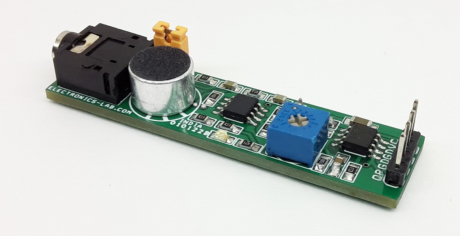
The project presented here is a sensitive sound sensor. The circuit converts sound frequency and outputs DC voltage. The board consists of LM358 OPAMP and LM2907 IC. LM358 is used as a dual-stage microphone preamplifier and LM2907 acts as a frequency to voltage converter. The circuit provides analog voltage output when it detects sound. The output of the sensor is proportional to the audio sound frequency detected through the condenser microphone. The output voltage swings from 3.5V to 10.8V proportional to frequency 330Hz to 933Hz. Output is zero when the sound frequency is below 330Hz. Users may try with other frequency ranges, which can be changed using the following formula, Vo = R9 × C6 × VCC × f. The sensor has better response and accuracy than many sound sensors available on the market. The operating Supply is 12V DC and consumes 20mA current. Jumper J1 and J2 are closed for normal microphone operation.
Accurate Acoustic Sensor – Sound Frequency to Voltage Converter – [Link]