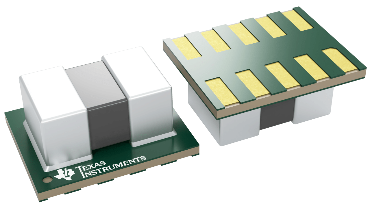
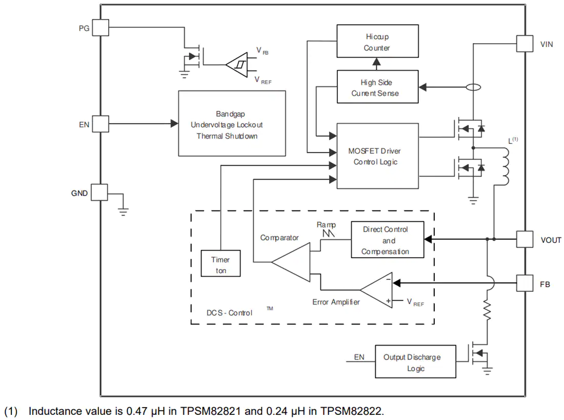
Texas Instruments TPSM8282x/TPSM8282xA 1A/2A/3A Buck Converter Power Modules are converters in a MicroSiP™ power module optimized for small solution size and high efficiency. The TI power modules integrate a synchronous step-down converter and an inductor to simplify design, reduce external components, and save the PCB area. The low profile and compact solution are suitable for automated assembly by standard surface mount equipment. To maximize efficiency, the converter operates in PWM mode with a nominal switching frequency of 4MHz and automatically enters Power Save Mode operation at light load currents.
In Power Save Mode, the device operates with typically 4µA quiescent current. Using the DCS-Control topology, the device achieves excellent load transient performance and accurate output voltage regulation. The EN and PG pins, which support sequencing configurations, bring a flexible system design. An integrated soft startup reduces the inrush current required from the input supply. Over temperature protection and hiccup short circuit protection deliver a robust and reliable solution.
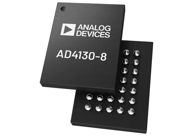
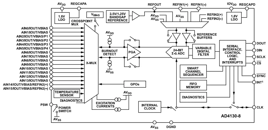
Analog Devices Inc.AD4130-8 Ultra Low Power 24-Bit Sigma-Delta ADC is a high precision measurement solution for low bandwidth battery-operated applications. The AD4130-8 features a fully integrated analog front end (AFE). It includes a multiplexer for up to 16 single-ended or eight differential inputs. The device also has a programmable gain amplifier (PGA), 24-bit sigma-delta (Σ-Δ) analog-to-digital converter (ADC), on-chip reference, and oscillator. These features improve the battery-operated lifetime, first in, first out (FIFO) buffer, and duty cycling.
Features
Ultralow current consumption (typical):
32µA continuous conversion mode (gain = 128)
5µA duty cycling mode (ratio = 1/16)
0.5µA standby mode
0.1µA power-down mode
Built-in features for system-level power savings
Current saving duty cycle ratio is 1/4 or 1/16
Smart sequencer and per channel configuration minimizes host processor load
Deep embedded FIFO minimizes host processor load (depth of 256 samples)
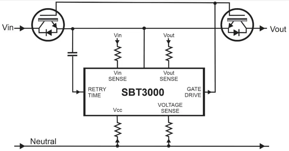
SiliconBrite SBT3000 Power Line Smart AC Switch Controller monitors incoming line voltage to ensure downstream loads operate within safe maximum continuous voltage ratings. The SBT3000 will automatically disable the AC switch in over-voltage line conditions. This will protect and isolate the load and minimize the potential of catastrophic failure modes.
The evolving embedded SIM technology in IoT devices offering cellular connectivity is increasingly becoming popular. More companies are adapting the concept of eSIM, especially for devices that reside in difficult-to-access locations or those that require you to pay a field technician to help change SIM cards in order to change carriers.
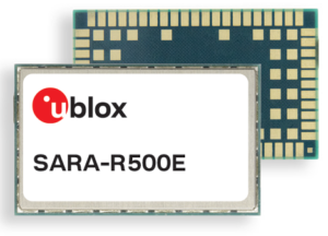
u-blox, a Swiss company expert in positioning and wireless communication technologies and services, has announced its first cellular module designed for size-constrained applications with high requirements in robustness and security. The SARA-R500E comes with an embedded SIM (eSIM) that lets you connect IoT devices to cellular networks thus eliminating the need for a separate SIM card and supporting components.
“SARA-R500E greatly simplifies logistics for device makers, as the eSIM is already integrated inside the module,” says Samuele Falcomer, Product Manager, Product Center Cellular at u-blox. “All the customers have to do is activate connectivity and choose the data plan that best fits their needs via the u-blox Thingstream IoT service delivery platform. Particularly those customers that are too small to negotiate dedicated data plans with mobile network operators will benefit from a competitively priced offering.”
The eSIM embedded in the module offers product developers and end-users some advantages:
Security of devices is increased since the eSIM cannot be stolen or removed.
End users do not need to insert the eSIM in by themselves, so product developers can build tightly sealed devices that meet the demanding IP67 and IP68 criteria (resistance to external forces like dirt, dust, sand and water).
IoT designs will use less board space as there will be no need for supporting hardware that normally holds and connects plastic SIM cards.
The SARA-R500E streamlines sourcing as it offers the module, data plans, and the SIM from one house.
Key Features of the SARA-R500E module include:
eSIM with various connectivity plans
Improved robustness and reliability
Reduced total solution footprint (cost-effective and power efficient)
Does not require external SIM or SIM holder
Pin-to-pin compatible with all the other modules in the u-blox SARA family
Uses the SARA-R5 AT command interface
Offers the option to access u-blox’s MQTT Anywhere service (this reduces bandwidth requirements for cellular data transfer, saving cost and power)
First variants to offer out-of-the-box connectivity on a North American LTE-M cellular network.
The module is suitable for rugged IoT applications such as smart meters, environmental sensors, surveillance cameras, etc.
Software protocol support:
Dual stack IPv4 and IPv6
PPP over IPv4 and IPv6
Embedded TCP/IP, UDP/IP, FTP, HTTP, DNS
Embedded MQTT and MQTT-SN
Embedded CoAP and LwM2M
Embedded TLS/DTLS
SIM provisioning (BIP)
u-blox has said that the first batch of the SARA-R500E modules will be available in September, this year. Other useful details on the module can be found on the product page.
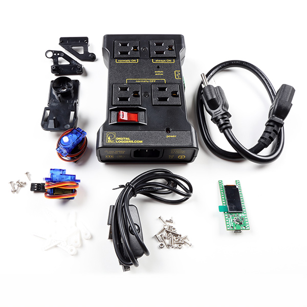
SparkFun, a Colorado-based embedded electronic device manufacturer, has announced the release of the Machine Learning and AI Concept Kit, which serves as a starting point for learning the fundamentals of prediction algorithms based on historical data and inputs. With the help of this kit, you can put your innovative idea into practice by utilizing artificial intelligence technology that “learns” from what you teach it. The kit will also provide you with an open-ended approach to machine learning and artificial intelligence, offering you many alternatives to realize new project ideas and enabling you to process incoming data against ML-trained datasets.
At the heart of the board is the Arducam Pico4MLTinyML Dev Kit, a single board system powered by Raspberry Pi’s RP2040 microcontroller. Furthermore, it is capable of powering TensorFlow Lite for Microcontrollers, a scaled-down machine learning program. The hardware has a monochrome sensor that makes image processing simple for most machine vision applications, a QVGA camera module with low power consumption, and a customizable 1-bit video data serial interface with video frame and line sync.
Meanwhile, you can view a live preview of the camera or the results of any of your ML models in real-time on the Pico4ML’s small 160×80 LCD TFT display, which is connected to the board through the SPI interface. The Pico4ML’s audio chip can generate PDM signals directly, and this integration enables the RP2040 to accept audio input. Additionally, a 2.5mW low-power 9-axis inertial measurement unit (IMU) is included for motion tracking.
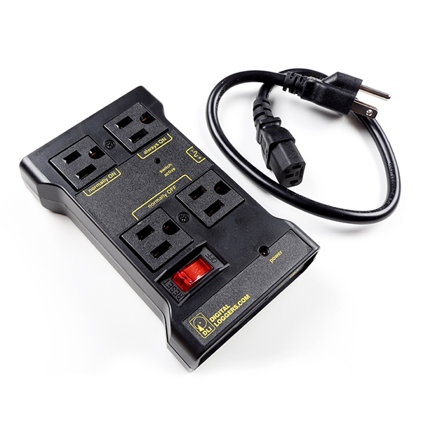
Besides Arducam, SparkFun includes an IoT Power Relay that allows you to design an Internet of Things project with reliable and secure power control. Therefore, using the Power Relay, you can simply manage the power going to a device with an Arduino, Raspberry Pi, or another single-board computer. Lastly, the pan/tilt included with this kit is an “easy to assemble” bracket that moves on two axes using servos, making it suitable for camera and helping-hand applications.
The Machine Learning and AI Concept Kit are available for $89.95 on the official product page. To get started, the company is directing electronic hobbyists to the Edge Impulse Studio platform, which offers full Pico4ML support.
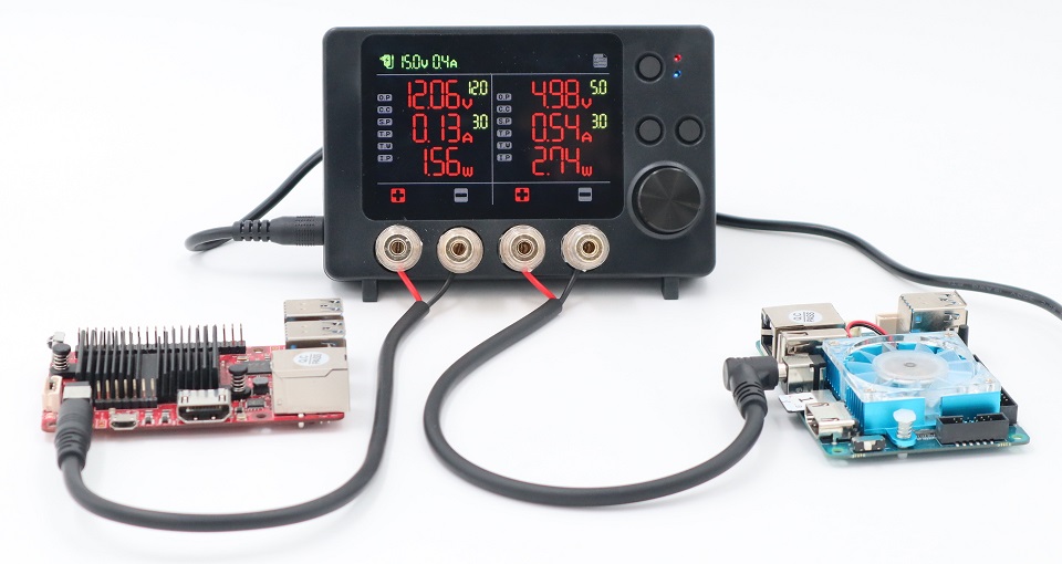
Low energy consumption is one of the key catalysts for scalable product launches. If your product is power-hungry, customers will certainly give you negative feedback. Consequently, every developer strives to make their products have extended battery lives, and they are increasingly looking for solutions to address the challenges with power consumption. Hardkernel, best known for its ODROID family of single-board computers, seeks to address this issue by making energy optimization more approachable. ODROID SmartPower 3, a compact, easily deployable power supply that monitors voltage, current, and power of the system load, can be used by embedded system developers to optimize energy consumption.
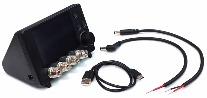
At the heart of the embedded device is the ESP32-S2 system-on-chip featuring a dual-core processor, but unfortunately no support for Wi-Fi or Bluetooth. Along with two DC plug cables that work with the ODROID-XU4, ODROID-N2, and ODROID-C4, the device comes with a USB-C data cable. The 15V/4A PSU is an optional power supply that you will additionally require. Additionally, it can be used for possible voltage drops, and software and hardware can be enhanced with applications that someday want to run on batteries.
Specifications of ODROID SmartPower 3
SoC: ESP32 dual-core processor via ESP32-WROOM-32E module
Rotary encoder to adjust voltage and ampere also works as Select/Setup button
CNX Software’s post has brought to our attention that, although the data is exhibited on display in real-time, the Smart Power 3’s capacity to transmit data to a host computer makes it most useful. The program only transmits data over USB to a serial interface at 921,000 bps even though ESP32 supports Wi-Fi communication. Further, a comprehensive report of the voltage, ampere, and wattage values is sent to a serial console programmer like GNU Screen rather than employing complex software to handle the data.
If you are interested in the SmartPower 3 tool, head to the product page where you can purchase the device for $45. For more information and links to the firmware source code, visit the official ODROID Wiki page.
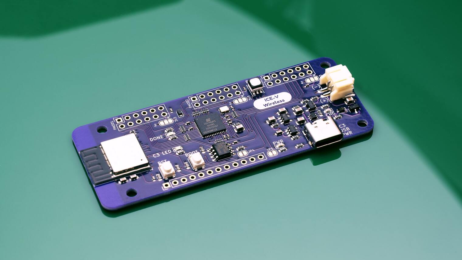
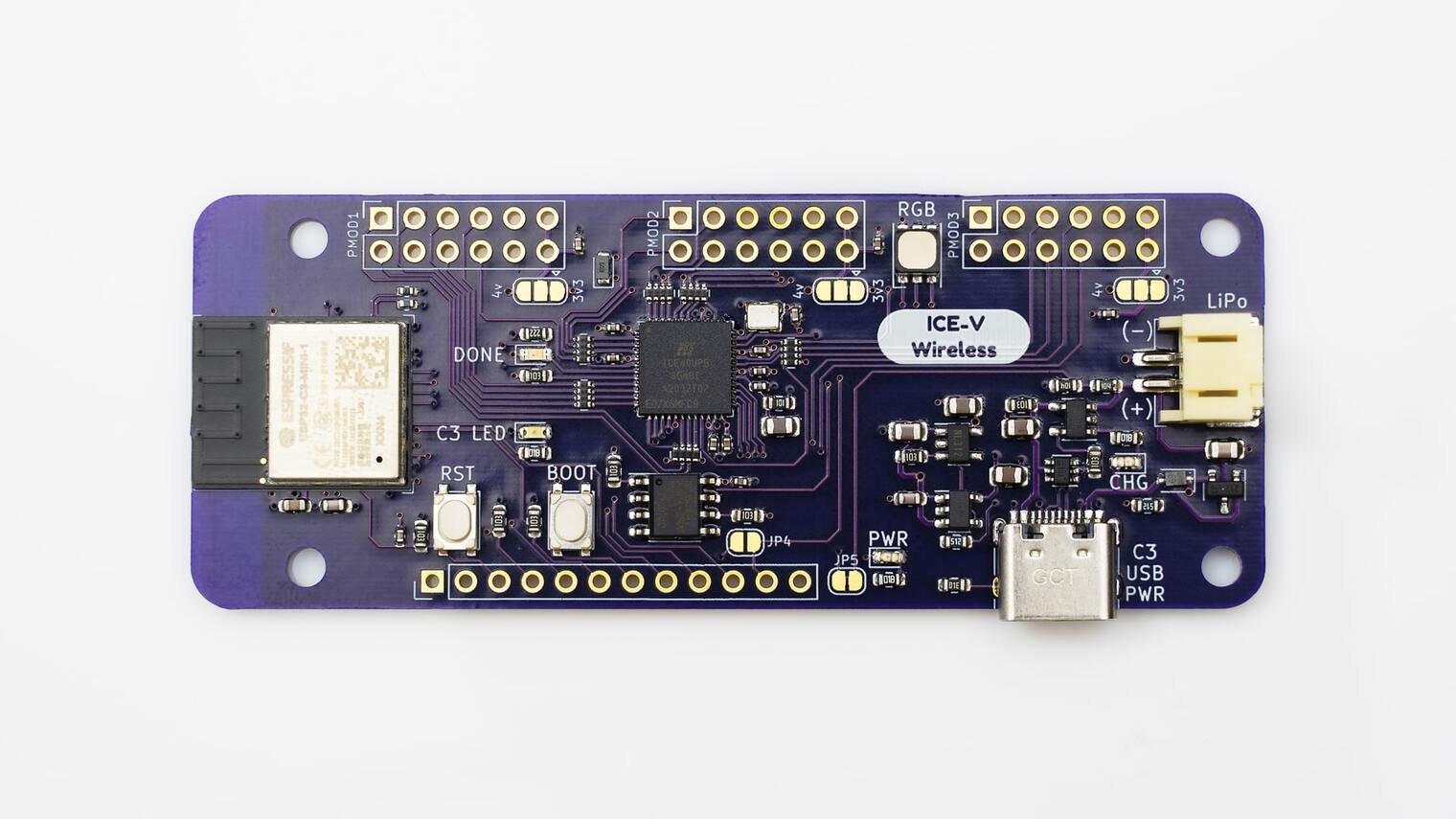
ICE-V wireless mini development board is currently active on GroupGets for community support, which features an ICE40UP5K FPGA and an ESP32-C3-MINI system on chip. The development board looks fairly similar to the Feather board, but there is no confirmation on the dimensions yet. The wireless interface driven by ESP32-C3 helps the hardware platform serve the growing demand for IoT use cases on an enterprise scale. The ESP32-C3 system-on-chip supports 2.4GHz Wi-Fi along with Bluetooth 5.0 powered by a RISC-V single-core microprocessor.
As mentioned earlier, the ICE-V wireless development board has the combined power of ICE40UP5K and ESP32-C3 SoC to deliver high computing performance in a small form factor. The interesting thing about ESP32-C3-MINI-1 is that it has an onboard PCB antenna. The general-purpose wireless connectivity module, ESP32-C3, has a rich set of peripherals making it an ideal choice for smart homes, industrial automation, healthcare, consumer electronics, etc.
Inside the ESP32-C3 system-on-chip is the ESP32-C3FN4 embedded 32-bit RISC-V single-core processor clocked up to a frequency of 160MHz and integrated 400kB memory and 384kB storage along with 4MB embedded flash. The key highlight of the SoC is the wireless connectivity, which includes support for Wi-Fi IEEE802.11b/g/n with simultaneous support for Infrastructure BSS in Station mode, SoftAP mode, Station + SoftAP mode, and promiscuous mode. Also comes Bluetooth Low Energy connectivity with speeds of 125 Kbps, 500 Kbps, 1 Mbps, 2 Mbps.
The other computing performance is delivered by the Lattice Semiconductor iCE40 ultra-low-power FPGA module for mobile applications, such as smartphones, tablets and hand-held devices. The flexible logic architecture features 5280 logic cells, offered in WLCS and QFN packages. The ultra-low power device has advanced 40nm low power process technology to deliver as low as 100µA standby current. The hardware includes integrated SPI and I2C blocks for interfacing with mobile sensors and application processors.
On the software side, the manufacturers, Qwerty Embedded Design, put out an update that the firmware development has been progressing well with over 65% funding reached. Eric, an engineer at Qwerty Embedded Design, was able to get the MicroPython port up and running on ESP32-C3 and has a script for flashing the FPGA. The GitHub repository has more details on the ICE-V-Micropython and how to get it working. If you are interested in supporting the project, head to the crowdfunding project page for more details.
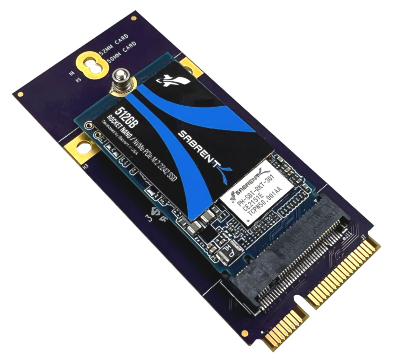
Gateworks is proud to announce the GW16148 Mini-PCIe to M.2 NVME storage adapter. It allows any of the Mini-PCIe slots with PCIe signalling on Gateworks SBCs to be used for a M.2 NVME storage drive. NVME allows for flash storage expansion that offers better performance than a microSD and provides an option when mSATA is not supported.
NVME is used widely in the consumer space, often featuring storage devices that are 80mm long and using 4x PCIe lanes built for desktop PCs. The Gateworks adapter allows for 1x PCIe lane with a maximum card length of 52mm. One of the ideal sizes for the GW16148 adapter is a 2242 form-factor. NVME drives are available from many different memory manufacturers and are not included with the Gateworks adapter.
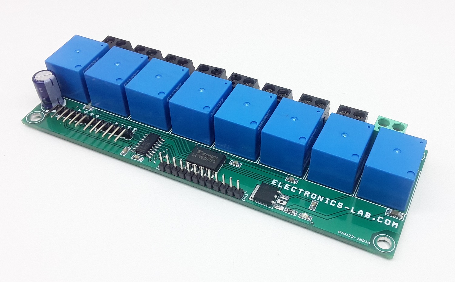
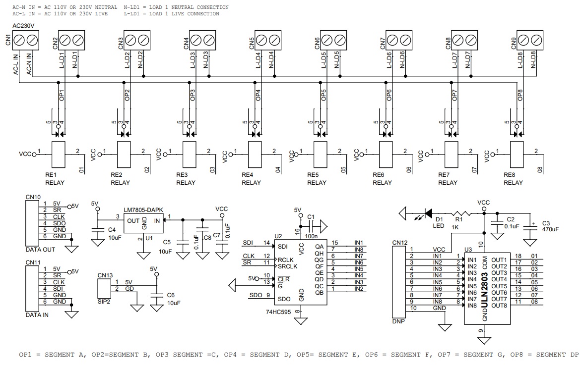
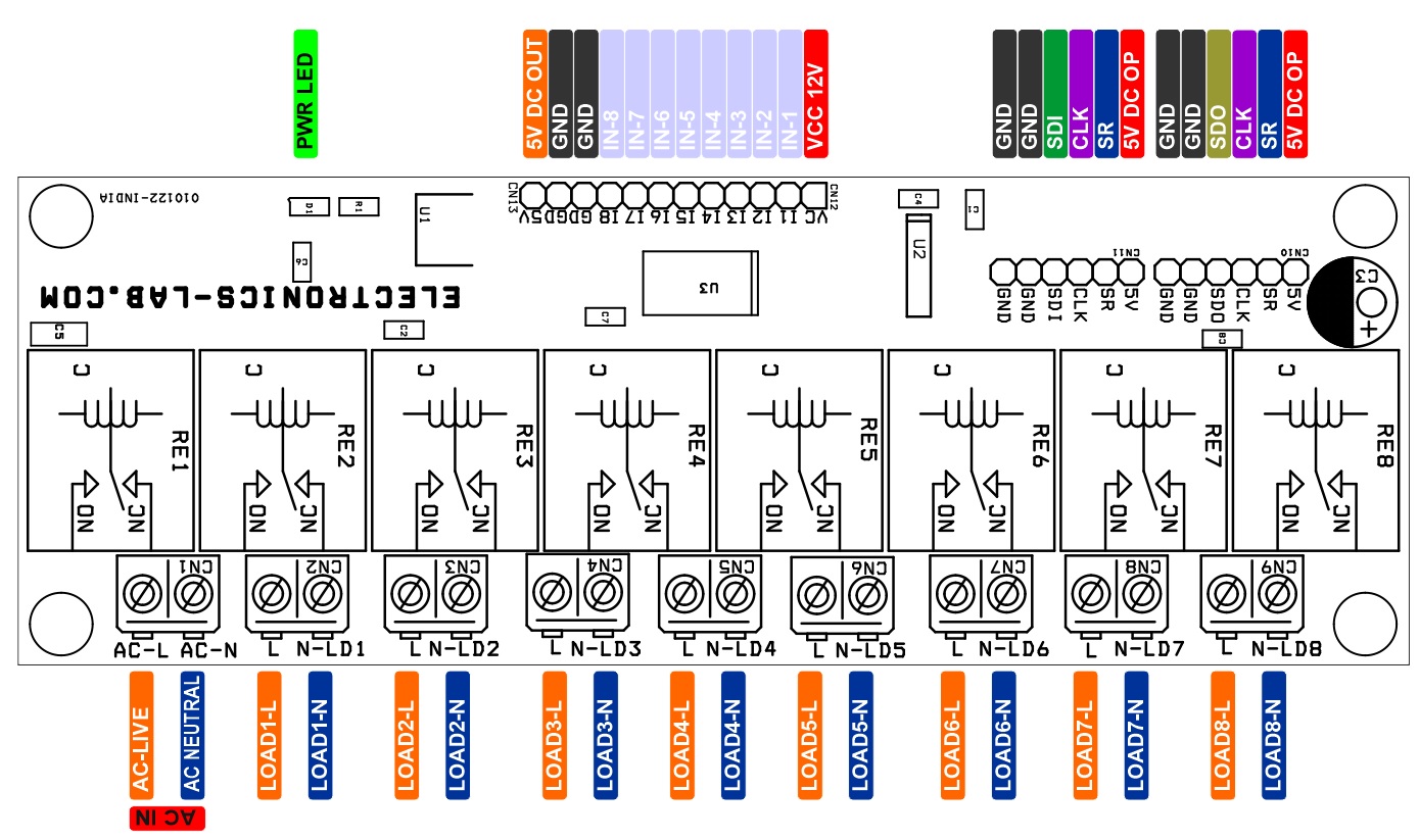
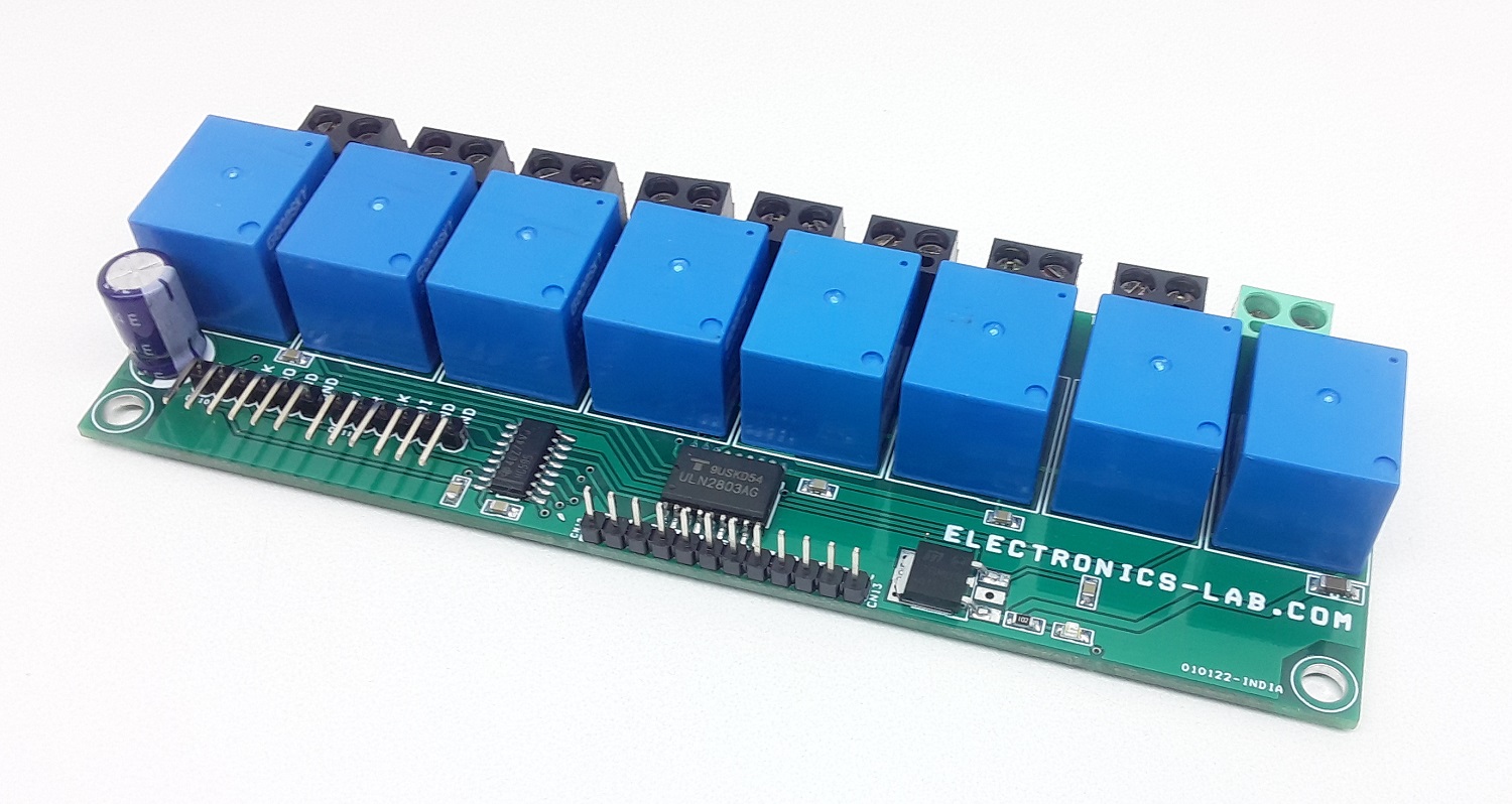
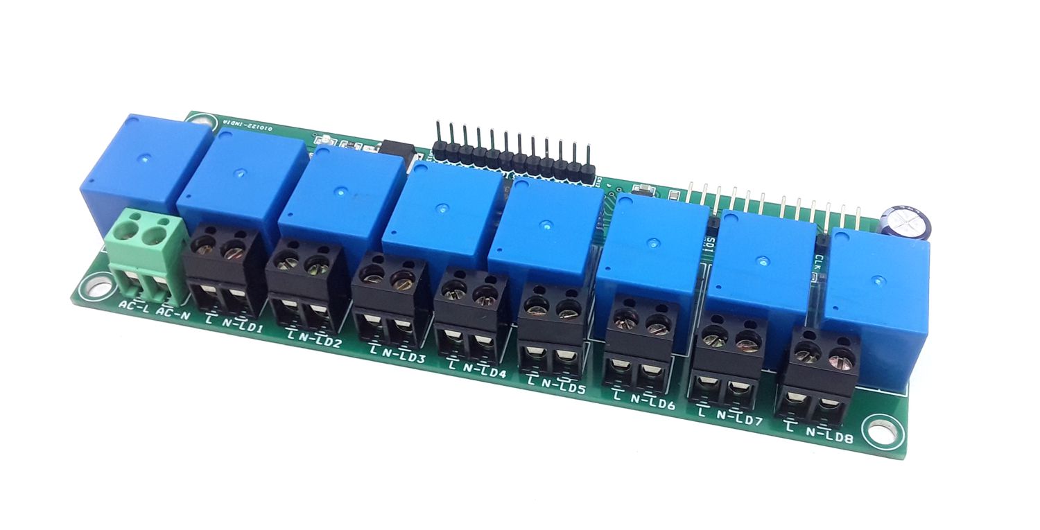
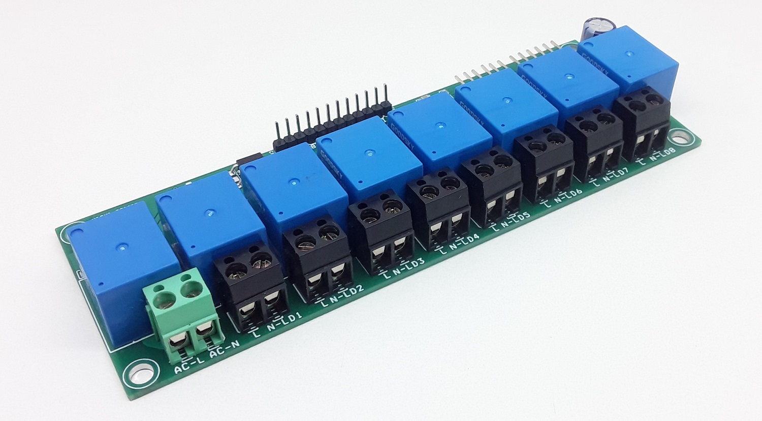
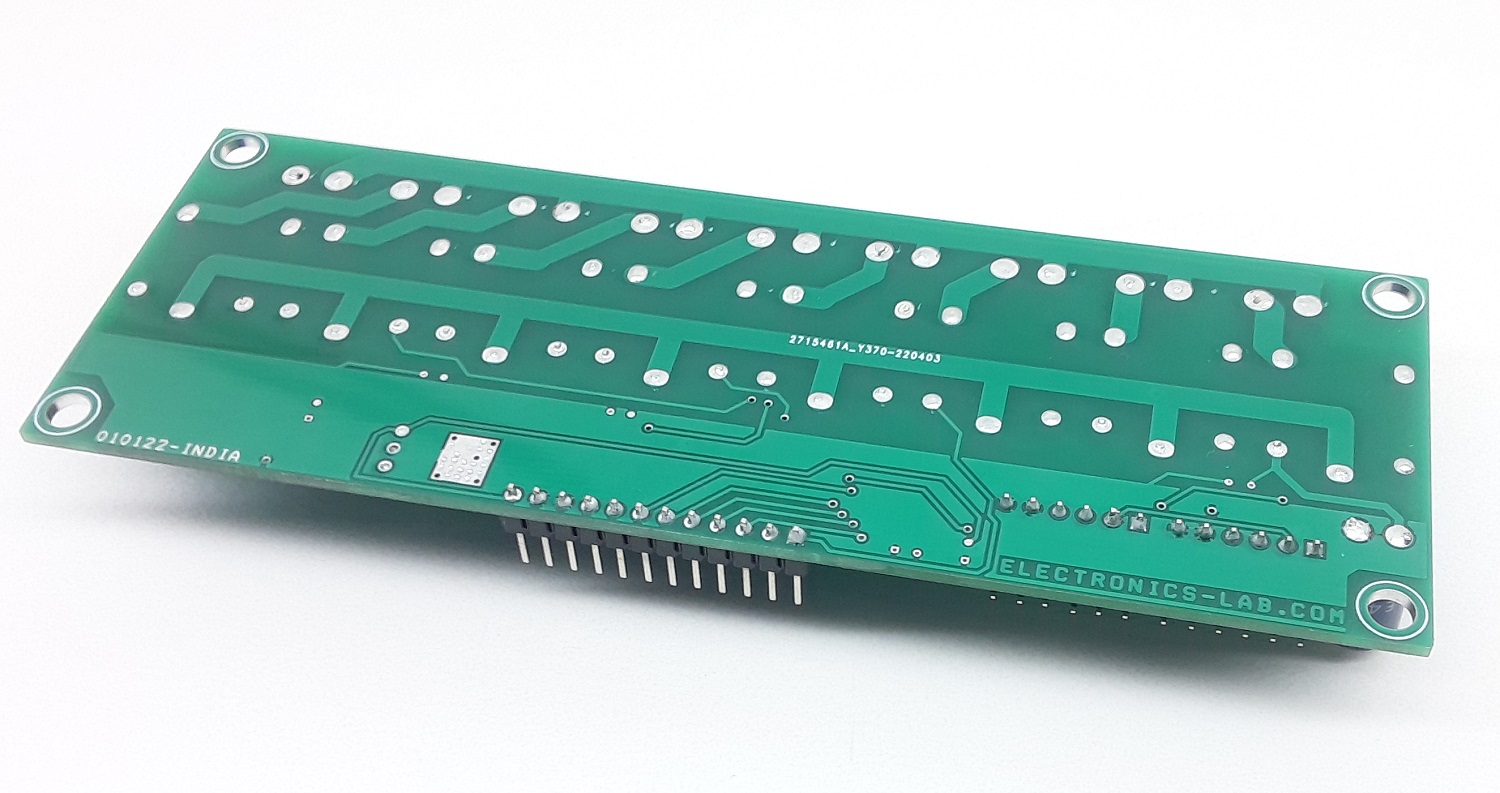
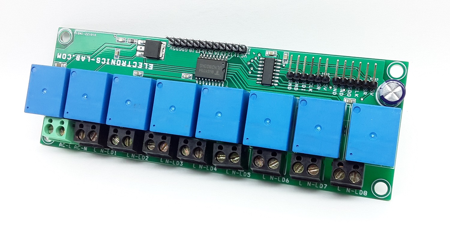
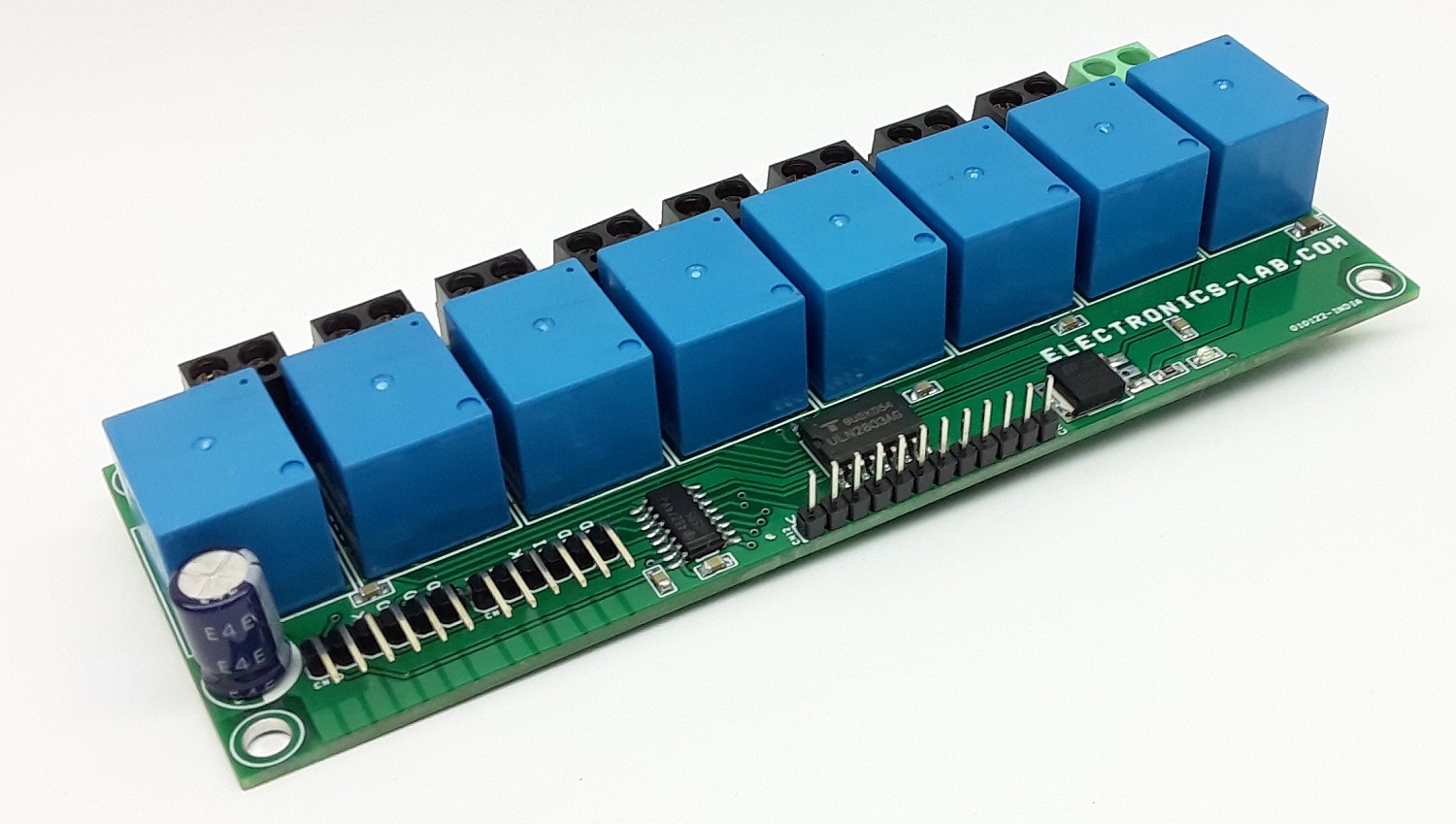
This is an SPI Interface multichannel relay board for high voltage AC or low voltage DC loads. It is ideal for controlling LEDs lights, coffee machines, fans, pumps, or other high-voltage electrical appliances. The board also breaks out the SPI header, so controlling other boards is still possible. Each relay can handle current up to 7A @ 250V AC/30V DC. This 8 x channel board is mainly designed for AC loads, but it can also drive DC loads, screw terminals on each channel enable the easy interface of the AC load, and each point is marked as AC-Live and AC Neutral. Refer to the connection diagram for the interface. The project consists of 8 x 12V relays with load capacity 7A @ 250V AC, ULN2803 8 channel relay driver, 74HC595 SPI to 8 output, 5V regulator 7805, power LED, screw terminals for loads and AC input, header connector for SPI input and output.
SPI Interface: 6-pin header CN11 is provided for data input and CN10 connector is the SPI output that can be interfaced with multiple boards.
Note1: This board also can be used with direct 8 channel TTL inputs by not installing the 74HC595 chip, use CN12 connector for 8 TTL inputs, IN1, 1N2,1N3,1N4, IN5, IN6, IN7, IN8
Note 2: Each relay can drive a load of up to 7 A, but it is not advisable to use full current as PCB tracks can not handle 7 A x 8 Channel = 56Amps. The maximum advisable load on each channel is 1.2A, the total load on each channel is 1.2A x 230V = 276W maximum.
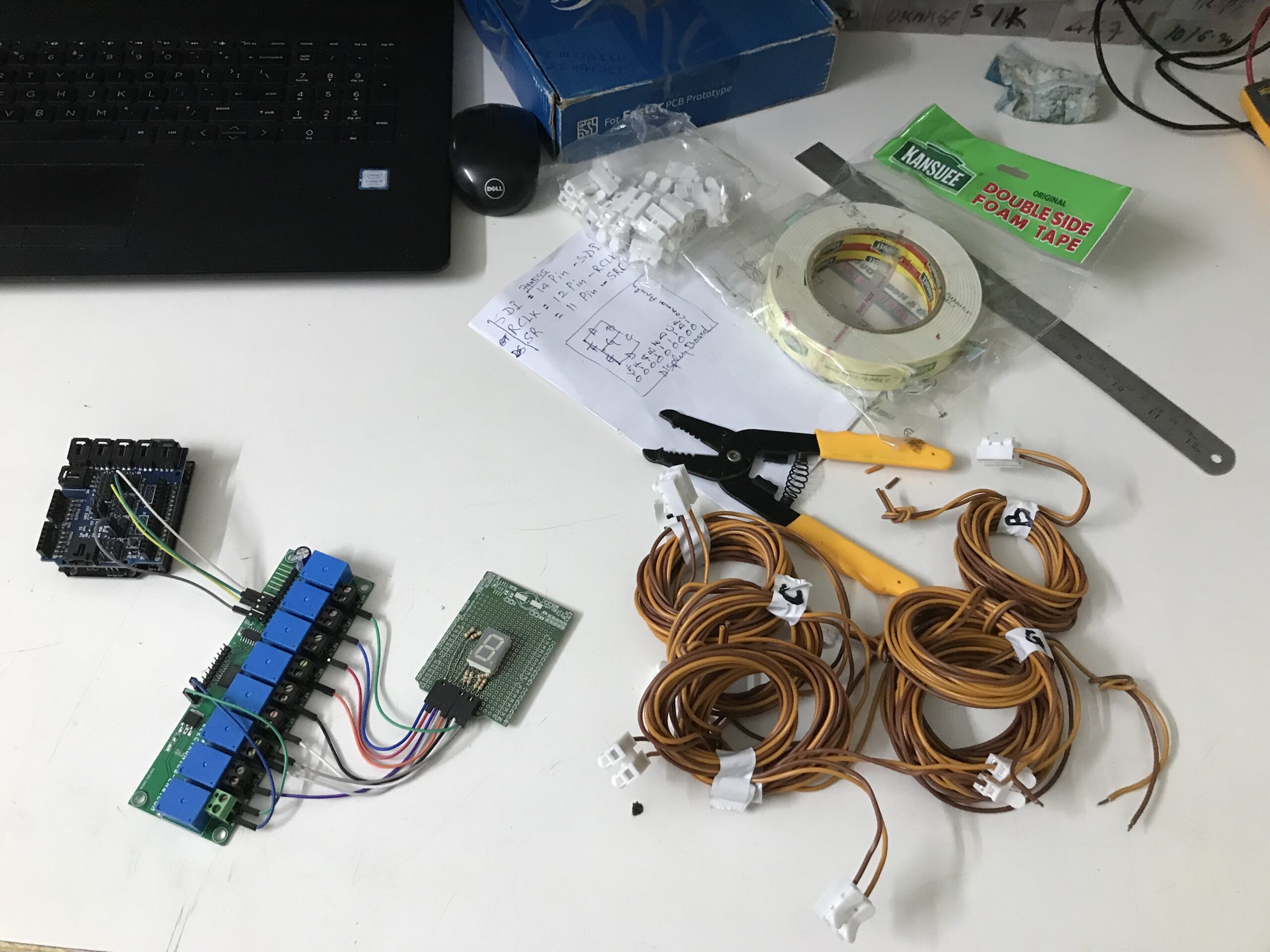
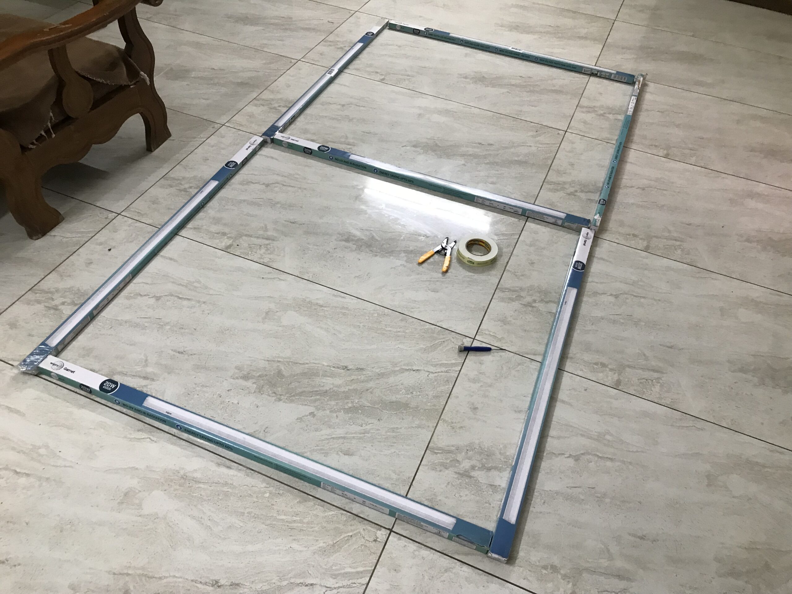
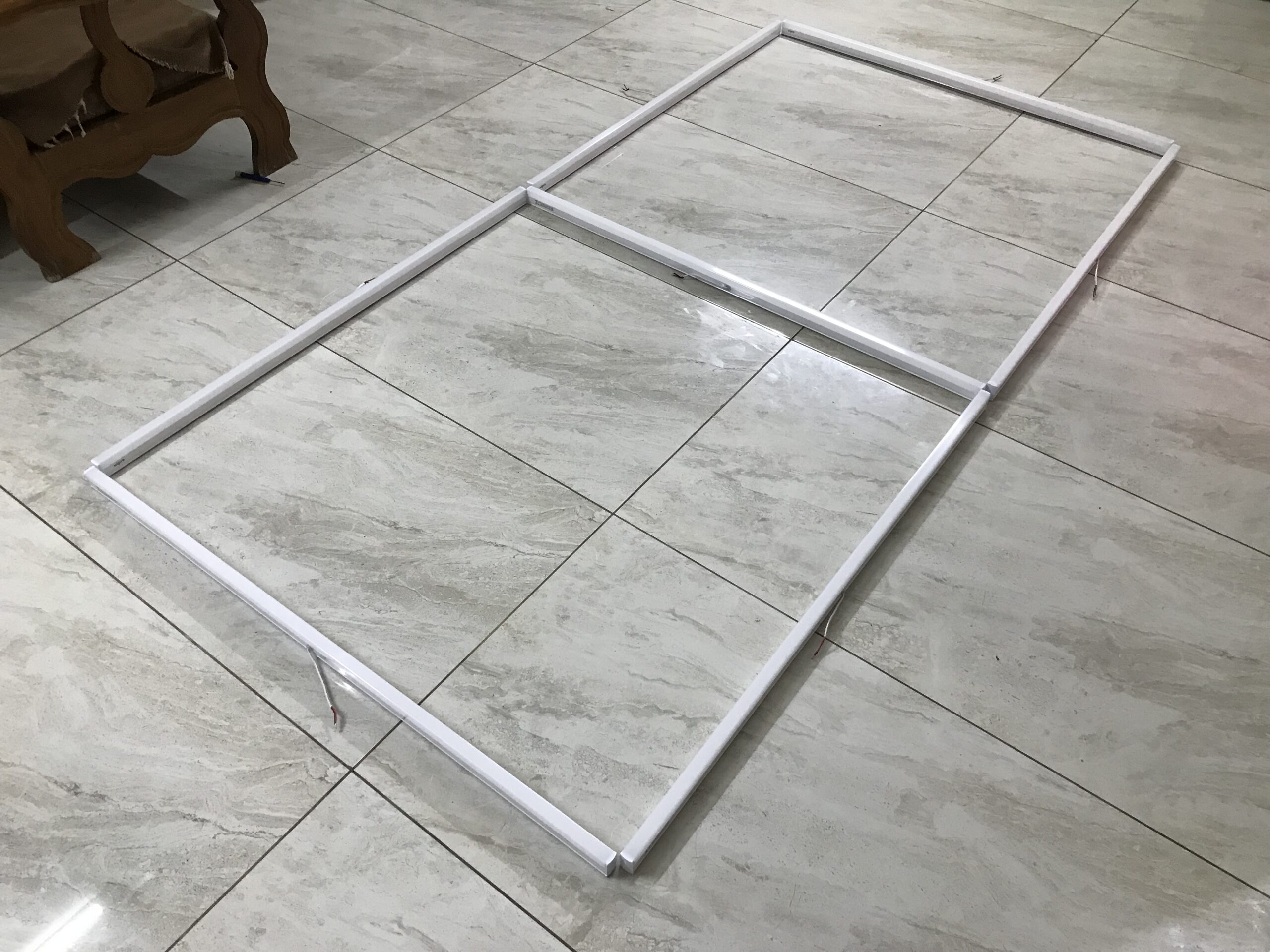
Controlling Large Size 7 Segment Display (Display size Approx. 8 Feet x 4 Feet)
We have created and tested a large-size 7-segment display with this board and an Arduino. Arduino example code is available as a download. Wiring between Arduino vs SPI 8 channel board as follows:
Pin 1:5V DC Output (200mA Maximum) >>Arduino 5V DC
Pin 2:SR/SRCLK/SH-CP (74HC595 Pin 11) >>Arduino Digital Pin D13
Each segment is made using 20W LED Batten (LED Tube Light) with Dimensions 113.5 x 2.8 x 6.8 cm, which works with 230V AC supply, user may use a smaller batten.
The project is tested with a single 7-segment display, but the user may use multiple displays with multiple boards, and use SPI outputs for other boards.
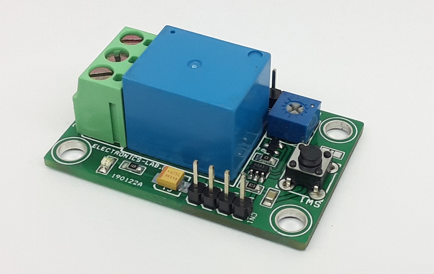
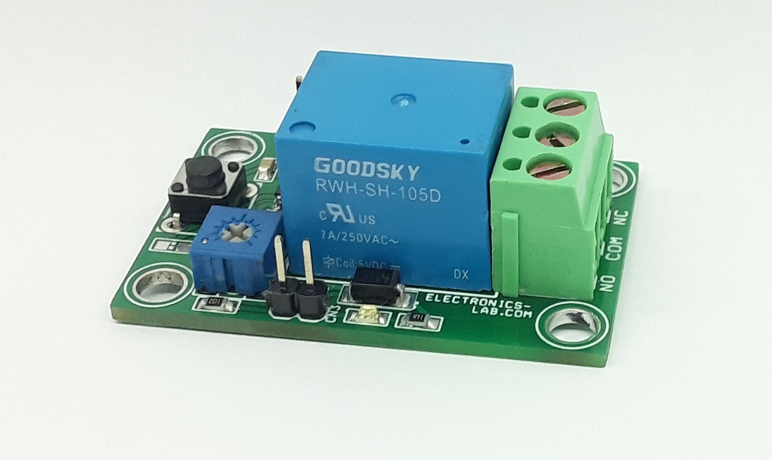
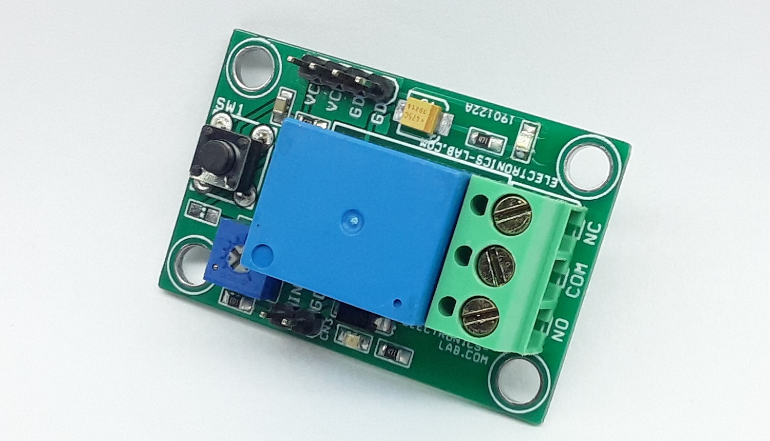
This project prevents/disconnects the load when an under-voltage condition occurs. The circuit latches the output when input sense voltage drops below the lockout threshold. Lockout threshold voltage can be adjusted using the onboard trimmer potentiometer PR1. Tactile switch SW1 is provided to reset the latch when input sense voltage is back to normal. The circuit consists of a MAX835 chip, 5V Relay, BC857 PNP transistor to drive the Relay, power LED, Relay/Output LED, and tactile switch. MAX835 chip features a level-sensitive latch, eliminating the need to add hysteresis to prevent oscillations in load-disconnect applications.
MAX835 micropower voltage monitors have a 1.204V precision bandgap reference, comparator, and latched output in a 5-pin SOT23 package. Using the latched output prevents deep discharge of batteries and disconnects the load from the power supply when Undervoltage is detected at input sense voltage. MAX835 has a push-pull output driver. Two external resistors set the trip-threshold voltage.
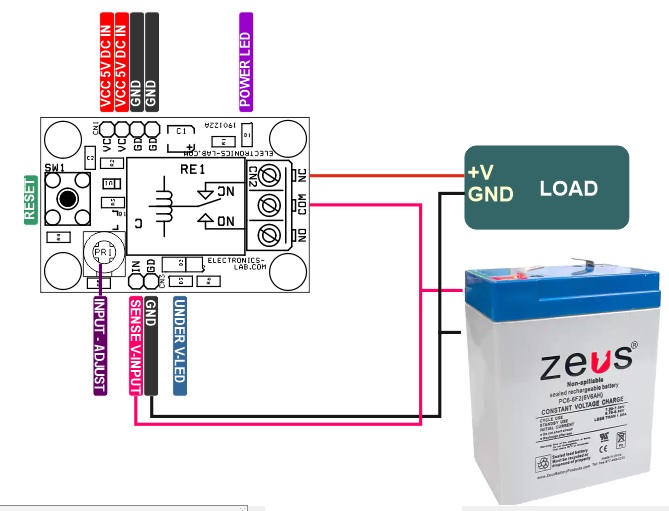
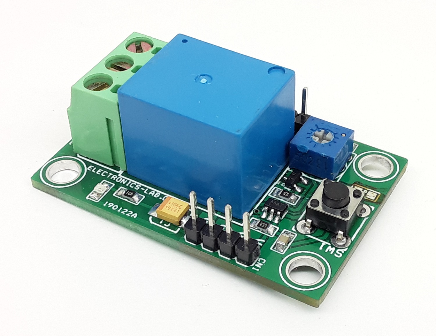
Operation
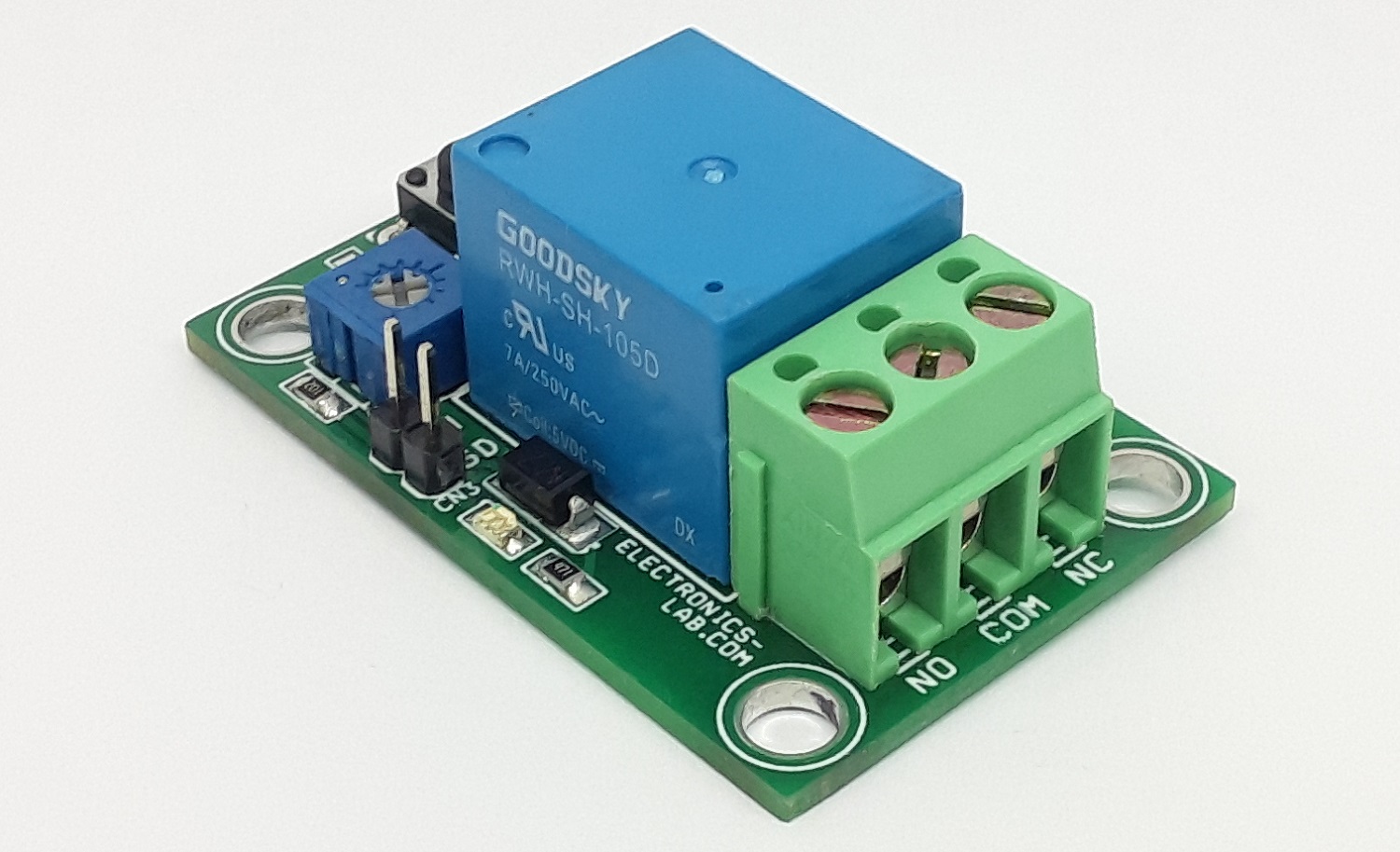
Connect an adjustable power supply to CN3 and apply input sense voltage in the range 3.4V to 8V, turn the PR1 trimmer potentiometer till the LED D3 is ON. Then the board is set for Undervoltage detection. For example, apply 4.90V to the CN3, rotate the PR1 so LED D3/Relay is on, the circuit is set for under-voltage detection threshold of 4.90V, now increase the input sense voltage to 5V and reset the latch using SW1.
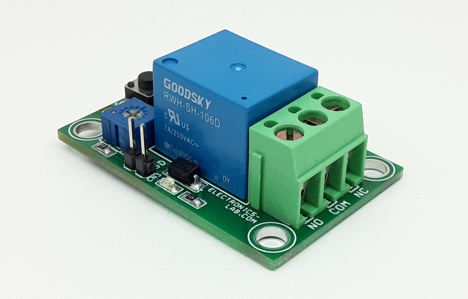
Note 1: Relay contacts can handle load current up to 7A, use higher contact relay for high current load. Relays up to 16A are available with the same PCB footprint (same dimensions)
Note 2: The project can also be used to prevent deep discharge of batteries, it disconnects the load when battery voltage drops below the set point, read the datasheet of MAX835 to configure the input voltage range of battery using PR1 trimmer potentiometer and resistor R5.
Note 3: Input sense voltage range is 3.4V to 8V and can be adjusted using trimmer potentiometer PR1. The circuit can be configured to detect higher voltage. To achieve that choose the right value for PR1 and R5. Read the datasheet of MAX835 for more info.
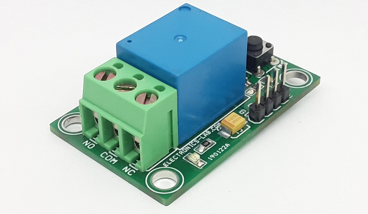
Connections
CN1 = Pin1 VCC, Pin 2 VCC, Pin 3 GND, Pin 4 GND
CN2= Pin 1 Sense Voltage Input, Pin 2 GND
SW1 = Reset Switch
D1 = Power LED
D3 = Function LED – Relay Output
PR1 = Trimmer Potentiometer Input Sense Voltage Adjust