First RISC-V-based SoC FPGA enters mass production with a smaller thermal footprint

Microchip Mi-V ecosystem

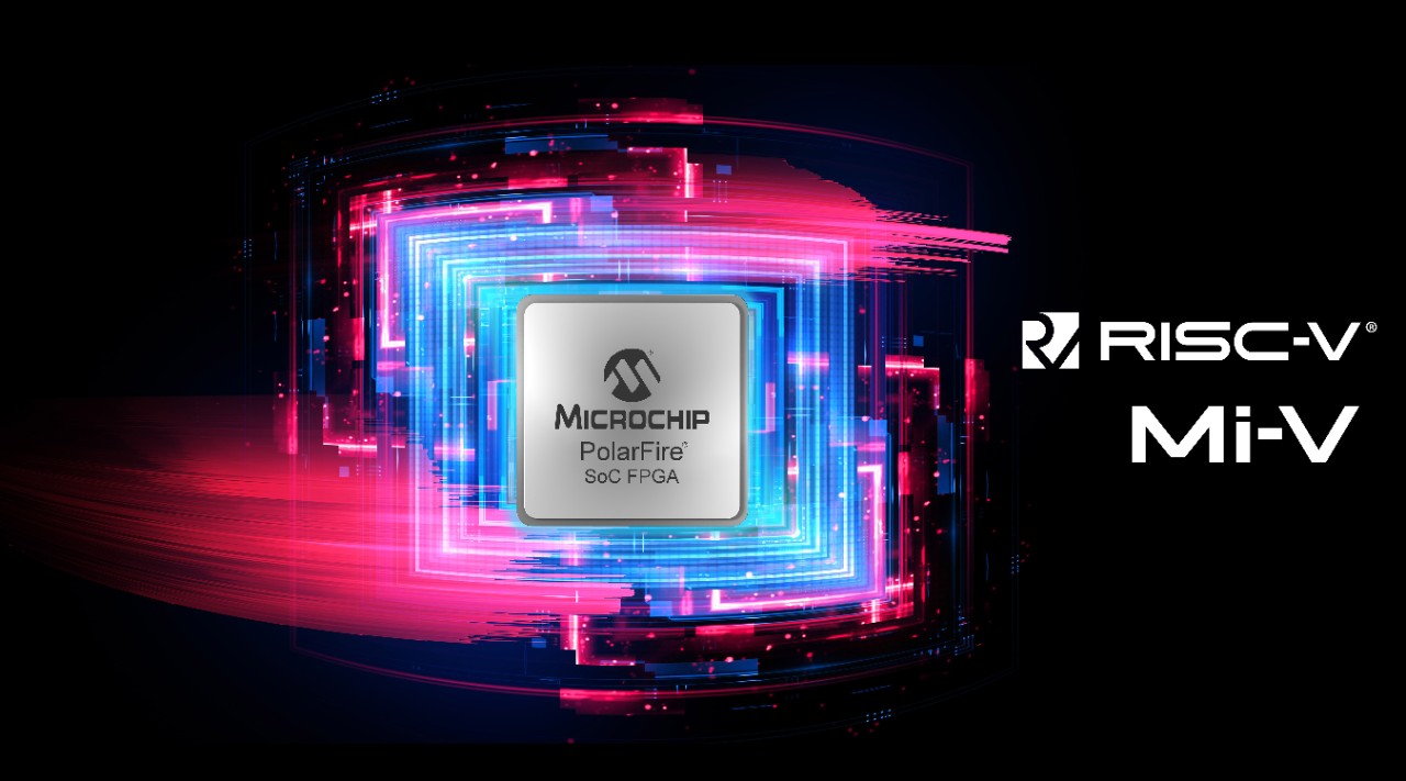
Microchip Technology has announced the first system-on-chip Field Programmable Gate Array (FPGA), MPFS250T, based on the open-standard RISC-V instruction set architecture to enter mass production. The news comes as the continued adoption of PolarFire SoC FPGA and exponential growth for the Mi-V ecosystem streamline RISC-V adoption across various industrial, IoT, and edge computing embedded devices.

Microchip previously announced the production qualification of MPFS025T, and the company has started taking orders for both the RISC-V SoC FPGAs. The volume production of Microchip MPFS250T extends the PolarFire SoC portfolio of multi-core RISC-V FPGAs to deliver a smaller thermal footprint and low power for embedded vision applications. Other applications include automotive, industrial automation, communications, defense, and IoT systems.

“We now have a large funnel of customers who have designed in the PolarFire SoC family with our suite of Mi-V tools and solutions,” said Shakeel Peera, vice president of marketing for Microchip’s FPGA business unit. “These customers have developed innovative products that bring best-in-class solutions to the market with superior thermal and power efficiency, as well as unprecedented compute capability in small form factors. We are now writing a new chapter in the history of RISC-V with the availability of production-qualified SoC PolarFire devices.”

The PolarFire SoC FPGAs provide configurable processing capabilities with real-time Linux-capable RISC-V-based microprocessor subsystems in the FPGA fabric. All developments are aligned to the Microchip Mi-V ecosystem roadmap and long-term commitment to public availability of the RISC-V SoC FPGAs. These devices leverage open-standard RISC-V ISA to enhance power efficiency, security, and reliability. Some new functionalities include deterministic Asymmetric Multiprocessing mode, which allows users to run Linux operating systems while running high-performance, real-time applications.

The PolarFire SoC FPGAs family delivers the combination of low-power consumption, thermal efficiency, and defense-grade security with a RISC-V CPU cluster and L2 memory subsystem. As part of the Microchip Mi-V ecosystem, several partners contribute to increasing RISC-V adoption through a comprehensive variety of IP, hardware, OS, middleware, debuggers, compilers, and design services.

“Microchip’s PolarFire SoC FPGA and Mi-V ecosystem provide an excellent platform to evaluate a Linux-capable multicore RISC-V-based SoC,” said Calista Redmond, CEO at RISC-V International. “The market now has a production-qualified RISC-V solution to procure and adopt in their designs. The FPGA fabric is an innovative platform that enables hardware acceleration for system design.”

At Mi-V Virtual Summit held on July 20-21, 2022, sixteen Mi-V partners will demonstrate their use cases using Microchip PolarFire SoC FPGA. For more information on the Microchip PolarFire SoC FPGA family, head to the official website.

SONOFF POW Elite enables Smart Power Consumption

SONOFF POW Elite

The SONOFF POW Elite is a smart meter switch that tracks the real-time power consumption of an appliance. This smart monitoring device aims to serve household appliances. It can withstand a maximum load of 20A to monitor the power consumption in an entire room. Driven with the new dual-core ESP32 chip offering 300 % more RAM and 200% higher clock frequency than the previous single-core ESP8622 chip. This smart power meter switch comes with reliable protection against overloading offering more safety.

Technical Specifications of SONOFF POW Elite

  • New dual-core ESP32 Xtensa Processor running at 240 MHz.
  • Supports 2.4GHz 802.11 b/g/n Wi-Fi 4 for fast connectivity.
  • The power input/output ratings are-
    POWR316D model – 100-240V~ 50/60Hz 16A Max
    POWR320D model – 100-240V~50/60Hz 20A Max
  • SONOFF POW Elite has 98 x 54 x 31mm with mountable DIN Rail.
  • The casing material used here is UL94v-0 standard tested PC VO

For more technical details see the user manual.

SONOFF POW Elite's features

Safety Protections by SONOFF POW Elite

Along with high-power appliance measuring capability, SNOW POW Elite comes with CE, FCC and SRRC certifications. The ability to prevent fire outbreaks makes this smart switch the highest flame retardant with a great safety grade. This device has been rigorously tested to meet the UL94v-0 safety standards.

SONOFF POW Elite's Safety Parameters

The built-in reset chip assures the device’s long-term reliability along with 0.87mm thicker and 2.5g heavier terminal wirings. Made with the most stable and dependable cold-rolled steel, the terminal wirings offer safe operation while carrying high currents. The presence of Tin in this smart power meter reduces the chances of safety hazards. The terminals that allow enormous current to flow use Tin in order to reduce overheating and hence ensure long-term reliability.

Smart Power Consumption at Fingertips

A user can access this SONOFF POW Elite smart power meter switch via the eWelink app. This app provides real-time data visualizations with timers to turn appliances on/off, LAN Control, and many more functions. It can also save up to 6 months of power consumption data. A user can view this data in the excel sheet on the linked phone. In order to receive an efficient electricity bill, a user may also establish a goal threshold restricting power use. This app also sends push notifications alerting the user after reaching the set threshold. Smart Power Consumption 
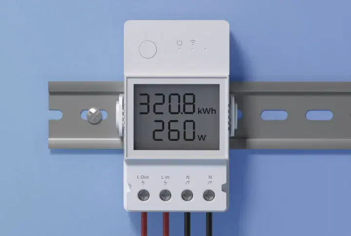
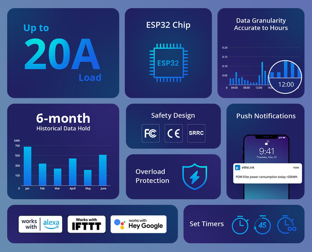
With such smart features, a user can easily save energy and money. The SONOFF POW Elite also gets access to third-party solutions such as Home Assistant, IFTTT, and Alexa Energy dashboard, making it a truly smart device. For more details on this smart power meter visit the official website.

A user can also check the accurate cumulative power consumption with the app. SONOFF POW Elite is a user-friendly gadget with smart features and excellent safety solutions. For pricing and more details about the device, visit the official website.

Maxim Integrated DS28E30 1-Wire® ECDSA Secure Authenticator

Maxim Integrated DS28E30 1-Wire® ECDSA Secure Authenticator is a cryptographic-based authentication solution that provides a root-of-trust to detect and prevent counterfeit products and to enable secure use management of limited life peripherals. The DS28E30 provides a highly secure and easily deployed turnkey authentication solution based on the FIPS-186 ECDSA standard. The DS28E30 combines ECDSA challenge and response authentication with secured EEPROM to store the keys and user data.

The DS28E30 features a core set of cryptographic tools derived from integrated blocks. These tools include an asymmetric hardware engine, a true random number generator (TRNG), 3Kb of secure EEPROM, a decrement-only counter, and a unique 64-bit ROM identification number (ROM ID). The ECC public/private key capabilities operate from the NIST-defined P-256 curve to provide a FIPS 186-compliant ECDSA signature generation function to support a bidirectional asymmetric key authentication model. The unique ROM ID is used as a fundamental input parameter for cryptographic operations and serves as an electronic serial number within the application. In addition, the authenticity of the chip can be verified with a Maxim-provided public key certificate.

The DS28E30 communicates over the single-contact 1-Wire bus at overdrive speed. The communication follows the 1-Wire protocol with the ROM ID acting as a node address in the case of a multidevice 1-Wire network.

The Maxim Integrated DS28E30 1-Wire ECDSA Secure Authenticator is offered in a tiny 1.2mm x 1.4mm Wafer-Level Package (WLP) ideal for space-constrained applications.

Features

  • Robust countermeasures protect against security attacks
    • All stored data is cryptographically protected from discovery
  • ECC P-256 secure compute engine
    • Preprogrammed and write-protected ECC P-256 key pair
    • FIPS 186-4 compliant ECDSA for strong challenge and response authentication
    • ECDSA authenticated R/W of configurable memory
  • SP800-90B TRNG used for secure ECDSA nonces
  • Supplemental features enable easy integration into end applications
  • 17-bit, one-time settable, nonvolatile decrement- only counter with authenticated read
  • 3Kb of secure EEPROM for user data, keys, certificate, and secure counter
  • Unique and unalterable factory-programmed, 64-bit identification number (ROM ID)
  • Authenticity verification with ECDSA Using preprogrammed maxim certificate
  • Advanced 1-wire protocol minimizes interface to single contact
  • Full-time overdrive communication speed
  • 1.62V to 5.0V input voltage range
  • 5µA typical input load current
  • High ESD immunity of 1-wire pin: ±8kV Human Body Model (HBM)
  • 40°C to +85°C operating temperature range
  • 1.2mm x 1.4mm WLP-4 package

Typical Application

more information: https://www.maximintegrated.com/en/products/embedded-security/secure-authenticators/DS28E30.html

LED Dimmer for Super High Brightness LEDs

This is a high-efficiency and reliability DC/DC converter with a dimming feature for super high brightness LEDs.  The project is built using L6902D chip. L6902 is a complete and simple step-down switching regulator with adjustable current limit. The current control loop with external sense resistors R6, R7, and R8 are able to work in constant current mode providing up to 350mA output current with an accuracy of 5%.  Potentiometer PR1 helps to control the dimming of the LEDs. PR1 is connected to the 3.3V reference pin of the chip. When the dimming (CS+) pin is grounded (0V) the maximum output current is provided (350mA) and vice versa when 3.3V is applied to the pin, the current provided is zero and so the LED is off.

Features

  • Supply 24V DC (Range 8 to 24V DC)
  • Load 6 x LEDs in Series (High Brightness LEDs)
  • Output Current Adjustable 0 to 350mA
  • Short Circuit or Over Current Protection
  • Switching Frequency DC-DC Converter 250Khz
  • 4 x 2.5MM Mounting Holes -PCB
  • PCB Dimensions 40.64 x 26.04 mm

Schematic

Parts List

NO.QNTY.REF.DESC.MANUFACTURERSUPPLIERPART NO
11CN12 PIN MALE HEADER PITCH 2.54MMWURTHDIGIKEY732-5315-ND
21CN22 PIN MALE HEADER PITCH 2.54MMWURTHDIGIKEY732-5315-ND
31C122uF/50VPANASONICDIGIKEYPCE4797CT-ND
41C210uF/35VYAGEO/MURATADIGIKEY
51C322KPF/50V SMD SIZE 0805YAGEO/MURATADIGIKEY
61C4220PF/50V SMD SIZE 0805YAGEO/MURATADIGIKEY
71D1MBRS360ONSEMIDIGIKEYMBRS360T3GOSCT-ND
81L1100uH/1AMPTDKDIGIKEY445-180842-1-ND
91PR15K TRIMMER POTENTIOMETERAMPHENOL PHIERDIGIKEY1993-1136-ND
101R12.2K 5% SMD SIZE 0805YAGEO/MURATADIGIKEY
111R28.2K 1% SMD SIZE 0805YAGEO/MURATADIGIKEY
121R31K 1% SMD SIZE 0805YAGEO/MURATADIGIKEY
131R49.1K 1% SMD SIZE 0805YAGEO/MURATADIGIKEY
141R527K 1% SMD SIZE 0805YAGEO/MURATADIGIKEY
153R6,R7,R81E 1% SMD SIZE 1206YAGEO/MURATADIGIKEY
161R9510E 1% SMD SIZE 0805YAGEO/MURATADIGIKEY
171R105.1K 1% SMD SIZE 0805YAGEO/MURATADIGIKEY
181U1L6902 SOIC8STDIGIKEY497-5330-1-ND
191D2LED RED SMD SIZE 0805LITE ON INCDIGIKEY160-1427-1-ND

Connections

Gerber View

Photos

Video

L6902D Datasheet

Linear Actuator Controller with Limit Switch to prevent Overextension and Retraction


The project described here is a very useful device for use with linear actuators. This controller prevents the actuator from reaching the physical movement limits of the actuator, thus it prevents burnout of motor and physical/mechanical damage to the actuator itself to the mechanical machine associated with it. It also allows for a smoother stopping motion once the end of travel is reached. The project is capable to drive DC brushed motor up to 3A, it supports 12V DC or 24V DC motors with few changes. Two limit switches are used on both sides of the actuator. The limit switches are available with 2 contacts normally open and normally closed. It is advisable to use normally closed contacts. The project consists of 2 DPDT relays, two 1N5402 diodes, Power LED, Motor direction LEDs, 2 x tactile switches, DC supply capacitor, screw terminals, etc.

Operation

Make all the connections as per the diagram, and install the limit switches at the end of the actuator. It is important to provide little offset space for motor movement. Power the board. Press any of the tactile switches SW1 or Sw2, actuator starts moving in one direction, once it hit the end limit switch, the switch is open, and the diode which is connected across the switch stops the current flow in that direction, and the motor stops. Now press the other switch, in this case, the current flow is reversed and the associated diode allows the motor to run in reverse directions and continue till it hit the other side of the limit switch. It is important to check the motor direction as per diode polarity, and swap the motor connections if the system doesn’t work properly or misbehaves.

The controller can drive 12V or 24V Motor (Maximum Current 3A)

12V DC Motor

  • Do Not Use Regulator U1, Jumper J1 closed, rest components as per schematic.

24V DC Motor

  • Open the Jumper J1
  • Resistor Value R1, R2, and R3 = 2.2K Ohms
  • Install U1 Regulator LM7812
  • In the case of a 24V Relay, don’t install the regulator, and use jumper J1.
Note: It is advisable to use an appropriate high current limit switch, as it should be able to handle the high current of the DC Motor, considering the peak current of the motor.

Features

  • Motor Supply 12V DC (for 24V Motor Read Note)
  • Maximum Load Current 3A
  • 2 x Tactile switch to drive Motor in CW/CCW
  • 2 x LEDs for Motor Direction
  • On-Board Power LED
  • Screw Terminals for Motor Connections, Limit Switch, Power Supply
  • 4 x 3mm Mounting Holes
  • PCB Dimensions 63.98 x 43.18 mm

Applications

  • Linear Actuators
  • Rotary Actuators
  • Machines
  • Automation
  • Furniture (Hospital Beds)

Schematic

Parts List

NOQNTY.REF.DESC.MANUFACTURERSUPPLIERPART NO
13CN1,CN2,CN32 PIN SCREW TERMINAL PITCH 5.08MMPHOENIXDIGIKEY277-1247-ND
22C1,C20.1uF/50V SMD SIZE 0805YAGEO/MURATADIGIKEY
31C3220uF/50V OR 470uF/35VWURTHDIGIKEY732-8463-1-ND
43D1,D4,D5LED SMD SIZE 0805LITE ON INCDIGIKEY160-1427-1-ND
52D2,D31N5402SMC DIODE SOL.DIGIKEY1655-1N5402CT-ND
61J12 PIN MALE HEADER PITCH 2.54MMWURTHDIGIKEY732-5315-ND
71MG12 PIN SCREW TERMINAL PITCH 5.08MMPHOENIXDIGIKEY277-1247-ND
82RE1,RE2RELAY DPDTOMRONDIGIKEYG2RL-24 DC12
93R1,R2,R31K 5% SMD SIZE 0805YAGEO/MURATADIGIKEY
102SW3,SW4TACTILE SWITCHNKK SWITCHDIGIKEYHP0215AFKP2-ND
111J1JUMPER SHUNTSULLIN INCDIGIKEYS9001-ND
121U1LM7812TIDIGIKEYDNP
RE1 & RE2 : 12VDC Coil Through HoleGeneral Purpose Relay DPDT (2 Form C)
RE1 & RE2 : OMRON Or GoodskyMI-SH-212L

Connections

Linear Actuator Diagram

Gerber View

Photos

Video


MI-SH-212L Datasheet

Under Voltage and Over Voltage Monitor for 5V

This project is built using MC33161 IC, which is a universal voltage monitor intended to be used in a wide variety of voltage sensing applications. The project offers an economical solution for positive and negative voltage detection. The circuit consists of two comparator channels each with hysteresis, a unique Mode Select Input for channel programming, a pinned out 2.54 V reference, and two open collector outputs installed with LED for visual alert for under-voltage and over-voltage situations. The project is configured for a 5V supply by default. It provides a visual indication when supply is lower the 5V and over 5V. Yellow LED indicates undervoltage and Red LED indicates overvoltage. Trimmer potentiometers PR1 and PR2 were provided to adjust the Undervoltage and Overvoltage range. Both inputs can be used as independent or combined (Single Input)

Note: The board is configured to detect Undervoltage and Overvoltage for 5V Supply, however, it provides the user with multiple choices and extensive flexibility for different applications circuits and configurations. It may be used in many combinations for various options, refer to the datasheet of the chip for various options, following components R7, R9, R10, Jumper J2, Buzzer BZ1-BZ2 provided to implement various circuits.

Connections

  • D1 Power LED – Green
  • D2 Under Voltage Alert LED – Yellow
  • D3 Over Voltage Alert LED – RED
  • CN2 Pin1 VCC, Pin2 Output 1, Pin 3 Output 2, Pin 4 GND
  • Jumper J1 Single or Independent Input Selection (Dual)
  • CN1: Pin 1 = VCC, Pin 2 = Optional, Pin 3= Input 1, Pin 4 = GND, Pin 5 = Input 2, Pin 6 = GND
  • PR1 Trimmer Potentiometer – Under Voltage Range Adjust
  • PR2 Trimmer Potentiometer – Over Voltage Range Adjust

Testing the Circuit

Close Jumper J1, Connect the 5V DC power supply to CN1 Pin1 +VC and Pin6 GND. Set the Adjustable power supply to 4.5V DC and connect it to Pin 3 or Pin5 of the CN1 Connector.  Turn the PR1 trimmer potentiometer carefully so the Yellow LED glows, now set the adjustable power supply to output 5.5V and turn the trimmer potentiometer PR2 such Red LED D3 should glow. Now, the project is configured and ready to be used. It is set to detect and indicate undervoltage of 4.5V and Over voltage of 5.5V. Connector CN2 can help for microcontroller interface, Output 1 and Output 2 Normally goes High or low when under/over voltage conditions are detected.

Features

  • Power Supply 5V DC (Range 5 to 12V DC)
  • Yellow LED for Under Voltage detection
  • Configured for 5V Detection
  • Red LED for Overvoltage Detection
  • Provides Visual Alerts when Under-Over Voltage is Detected at input 1 and Input 2
  • Output 1 and Output 2 for Micro-Controller Interface
  • LEDs can be Replaced with Audible Buzzer (Low Current Buzzer 10mA maximum)
  • 4 X 2.5 MM Mounting Holes
  • PCB Dimensions 53.66 x 24.92mm

Schematic

Parts List

NO.QNTY.REF.DESC.MANUFACTURERSUPPLIERPART NO
18BZ1,J2,BZ2,R3,R5,R7,R9,R10DNPDO NOT INSTALL
21CN16 PIN MALE HEADER PITCH 2.54MMWURTHDIGIKEY732-5319-ND
31CN24 PIN MALE HEADER PITCH 2.54MMWURTHDIGIKEY732-5317-ND
41C10.1uF/50V SMD SIZE 0805YAGEO/MURATADIGIKEY
51C210uF/16V SMD SIZE 1210 CERAMIC OR TANTLUMMANUFACTURERDIGIKEY
61D13MM LED GREENAMERICAN OCTODIGIKEY2460-L314GT-ND
71D23MM LED YELLOWAMERICAN OCTODIGIKEY2460-L314YD-ND
81D33MM LED REDAMERICAN OCTODIGIKEY2460-L314HD-ND
91J12 PIN MALE HEADER PITCH 2.54MMWURTHDIGIKEY732-5315-ND
102PR1,PR25K TRIMMER POTENTIOMETERBOURNSDIGIKEY3362H-502LF-ND
113R1,R2,R4470E 5% SMD SIZE 0805YAGEO/MURATADIGIKEY
122R6,R810K 1% SMD SIZE 0805YAGEO/MURATADIGIKEY
131U1MC33161 DIP8 or MSOP8ONSEMIDIGIKEYMC33161DMR2GOSCT-ND
141J1/SHUNTSHUNTSULLINS CONCTDIGIKEYS9001-ND

Connections

Gerber View

Photos

Video

MC33161 Datasheet

SmartCow announces FleetTrackr– AIoT device management platform

SmartCow FleetTrackr

Malta-based AI startup SmartCow has announced the availability of a new AIoT device management platform, FleetTrackr, for simplified deployment and centralized management of edge AI systems. All of this will be done through a unified platform using a hybrid-cloud service, specifically for applications, including smart cities, security, surveillance, and traffic management. This is an essential tool for enterprises where thousands of edge IoT devices are deployed in the edge network.

For enterprise-edge AI applications, thousands of edge sensors are simultaneously transmitting data for processing and real-time response. SmartCow FleetTrackr will be used in such situations where there are several AIoT devices connected for smart manufacturing using AI for inventory management, large-scale surveillance, security deployments, and smart retail automation.

“Fleet management software will revolutionize companies’ ability to digitally transform their business operations, and FleetTrackr is at the forefront of specialty AIoT device management software,” said Ravi Kiran, SmartCow at CEO. “We recognize the need for responsive, flexible, and remotely-operated AI solutions as demand increases for efficient, smart technology.”

SmartCow FleetTrackr Architecture

One of the concerns of the thousands of edge devices deployed on the edge network is reprogramming and updating these devices. With SmartCow FleetTrackr, there comes Firmware-Over-the-Air (FOTA) functionality, which allows the user to manage, monitor, and update edge devices over the air. FleetTrackr’s 24×7 remote management also includes security and privacy features with a 30% reduction in maintenance, time, and labor costs.

There are several key features provided by the company, but some of the important ones, include device lifecycle management, Firmware-Over-The-Air updates, predictive maintenance capabilities, issue management, Out-Of-Band functionality, and support for multiple IT environments. The Out-Of-Band functionality gives you the flexibility to remotely send updates to your device and allows firmware backup and recovery whenever the device goes wrong.

“FleetTrackr allows administrators to update all the devices in the desired network with new software without spending weeks planning and executing deployment plans,” continued Kiran. “FleetTrackr enables users to not only identify problems with large fleets of devices, but to perform software updates as well as backup and restore firmware when a device turns out to be faulty, making the experience seamless, efficient, and secure.”

SmartCow recently introduced the Apollo development kit integrated with the Jetson Xavier NX supercomputer. The SmartCow Apollo development platform is equipped with onboard sensors, such as four microphones, two speaker terminals, two 3.5mm phone jacks, an 8MP IMX179 camera module, and an OLED display.

Miniware MDP-XP Smart Digital Power Supply kit

MDP-XP Smart Digital Power Supply Kit

Miniware is one of the versatile technical service companies that has introduced its programmable linear DC power supply, MDP-XP. During the interfacing procedure, this MDP-XP (Mini Digital Power Supply) can link numerous devices at the same time. With MDP-XP’s modular design, it enables you to improve the fundamental capabilities of a device. Along with its unique user interface, it is a low-cost, reliable, and stable DC power supply. An STM32 smart chip controls this MDP-XP, allowing the users to customize the parameters and upgrade the firmware at any time. It includes a Display Control Module (MDP-M01) and a Digital Power Module (MDP-P905).

MDP-M01 Display ControlMDP-M01 display control

With the MDP-M01 Display Control, you get a quick and easy-to-learn interface that enhances the user experience. Equipped with a 2.8-inch 90° flipping TFT screen, it has the potential to display the real-time voltage/current waveform. It also supports data statistics, and automatically pairs and controls 6 sub-modules or the display power modules. This Display Control features dual thumb wheels which consist of a value wheel and the menu wheel. The value wheel controls the adjusting values whereas the menu wheel can be utilised for selecting the options.

MDP-P905 Digital Power ModuleMDP-P905 digital power module

On the other hand, the MDP-P905 Digital Power Module provides a high-efficient linear output of up to 95% with 0.25mV ultra-low ripple. This Power Module delivers a 4µs high transient response along with precise fine-tuning of 0.001V and 0.001A. The 4MM high-quality copper interface plays a big role in providing protection against high current corrosion. The DC input voltage range is between 4.2V and 30V, which further reduces to 2.7V after startup, meanwhile, the output voltage is 30v/5A.

Features of MDP-XPMDP-XP features

  • A wireless connection of 2.4G makes it possible to achieve a multichannel combination at the power of 90W per channel. This wireless connection supports the Display Control, as well as the six Digital Power Modules.
  • The low load regulation contributes to the accurate power supply. On the other hand, the intelligent line loss compensation ranging from 5mR to 100mR results in tremendous power transfer.
  • In addition to presenting precise waveforms, this software can save data up to 7MB with a maximum recording limit of 24 hours. The load and the power adjustment rates are <±0.01^% and it also supports Qualcomm’s quick QC3.0 port.
  • In addition to its high cost-effective programmable linear DC power supply, it is necessary to consider the safety parameters too. Hence, MDP-XP offers 6 safety protections, including input overvoltage, under-voltage, anti-reverse connection, anti-backflow, overtemperature, and overcurrent.
  • The programmable output, timing output, sequential control, automatic compensation, and other innovative features fulfil a huge spectrum of testing requirements.

MDP-XP Kit

This high power supply unit can be used in R&D laboratories for universal testing and teaching experiments, maintenance of digital devices, testing of power supplies in devices, or to provide refined power for digital-analog hybrid circuits which have high accuracy and for devices that deliver Hi-Fi audio and for more applications and detailed specification visit the product page.

The smart MDP-XP Digital Power Supply kit is available at a price of just $210.00. With this price, you get an MDP-M01 display module, an MDP-P905 power module, a 2.5mm Audio to Micro USB Cable for data, and two 4mm Banana Plug to Alligator Clip output cables, a 2.5mm Audio to USB Type-A cable, and a user manual. For more information about this product visit Dfrobot’s official website.

Espressif ESP32-C5 SoC with dual-band Wi-Fi 6 and Bluetooth 5 Low Energy

Espressif ESP32-C5

One of the very famous embedded SoC designers and manufacturers, Espressif, has recently announced the launch of yet another 32-bit microcontroller– ESP32-C5 featuring its first dual-band Wi-Fi solution. As the company claims, the ESP32-C5 system-on-chip is a follow-up module to the ESP32-C6 SoC which was announced last year. ESP32-C6 came with the support for Wi-Fi 6 and Bluetooth 5 Low Energy wireless connectivity which was an upgrade from ESP32-C3 SoC. The new ESP32-C5 SoC has an integrated MCU of 2.4GHz and 5GHz dual-band Wi-Fi 6 along with Bluetooth 5 Low Energy connectivity.

The ESP32-C5 SoC is equipped with dual-band Wi-Fi 6 (IEEE 802.11ax) radio and IEEE 802.11b/g/n standard for back compatibility. Wi-Fi 6 support has been an important parameter for its adoption due to its optimized performance for edge IoT devices. The SoC supports 20MHz bandwidth for IEEE 802.11ax mode and an optional 20/40MHz bandwidth for standard IEEE 802.11b/g/n modes.

At the heart of the ESP32-C5 is the 32-bit RISC-V single-core processor that can be clocked up to a frequency of 240MHz. The hardware comes with a 400kB of SRAM and 384kB ROM with support for external flash storage. There are 20 programmable GPIOs that support commonly used peripherals that allow the user to interface camera and display modules. The module also incorporates SDIO 2.0 Slave interface.

Espressif ESP32-C5 SoC

“The ESP32 SDIO Card peripherals (Host, Slave) share two sets of pins as below table. The first set is usually occupied by the SPI0 bus, which is responsible for the SPI flash holding the code to run. This means SDIO slave driver can only run on the second set of pins while SDIO host is not using it.”

Enterprise customers who deploy thousands of edge devices into the edge network are looking for low latency and stable connectivity using the 5GHz band. Espressif ESP32-C5 SoC will provide robust wireless connectivity across this spectrum for less traffic and lower interference for mission-critical applications. Wi-Fi 6 is supported by ESP32-C5 and comes with several upgraded features to provide benefits for edge devices. An example taken by the company is the support for the OFDMA mechanism for uplink and downlink communication along with MU-MIMO capacity for download. This feature is a key highlight of the hardware as it improves efficiency and provides low latency communication even in a congested wireless environment.

On the software side, Espressif ESP32-C5 can be used on Espressif’s open-source ESP-IDF suite, which already powers other ESP modules. Due to its robust wireless connectivity, several customers might want to use ESP32-C5 as a communication co-processor with an external host, for which the company has provided ESP-AT and ESP-hosted SDKs. For more information on the Espressif ESP32-C5, visit the official press release.

Imagination’s first real-time 32-bit RISC-V Catapult CPU: IMG RTXM-2200

Imagination Tech IMG RTXM-2200

In 2021, Imagination Technologies revealed that it was developing multiple processors based on Catapult’s open RISC-V architecture. IMG RTXM-2200, a 32-bit RISC-V real-time embedded CPU core, is the first addition to the Catapult family introduced by the firm. The latest news found the IMG RTXM-2200 processor is proposed to focus on real-time computing in sensors, storage controllers, and networking solutions. The all-new design is a 32-bit embedded solution with a wealth of features that can be adapted to a number of high-volume applications.

“We are excited to announce IMG RTXM-2200, our first real-time RISC-V CPU, which underpins our continued commitment to driving growth for the RISC-V ecosystem. Imagination now has a unique and broad portfolio of computing IPs, including GPU, AI accelerators, and now CPU, designed for this innovative architecture”, says Chris Porthouse, Chief Product Officer of Imagination.

The new core is highly scalable and offers Level 1 cache sizes of up to 128 KB for reliable performance, as well as up to 128 KB of tightly coupled memory (both instruction and data). The architecture provides several floating-point formats, such as single-precision and the BFloat16 format for compact AI frameworks, and a RISC-V Bit Manipulation extension to improve code density. Thereby, manufacturers can deploy AI applications through this core without needing an extra chip, which reduces silicon space and enables a more optimized and cost-effective design for AI cameras and smart metering applications. The company has also disclosed an optional interrupt module, debug module, breakpoint triggers, and trace systems for development and debugging.

 “RISC-V International is excited to witness Imagination maintaining its momentum by launching its first licensable 32-bit embedded real-time processor since the announcement of its entry into the RISC-V CPU IP market”, said Calista Redmond, CEO of RISC-V International. “This underlines the expansion of the RISC-V architecture as developers take advantage of this flexible technology to address multiple market requirements. We are pleased to see Imagination’s commitment to driving ecosystem growth with the delivery of its SDK and the support of open-source operating systems.”

Imagination claims that it will offer extensive support for software development kits (SDKs) in addition to compatibility with both Linux-based and FreeRTOS real-time operating systems. Catapult Studio Integrated Development Environment is a cutting-edge IDE built on Visual Studio code that provides a familiar environment for modern developers and designers. IDE supports all Linux distributions and is compatible with Windows, Ubuntu, CentOS, and macOS. To simulate power consumption and energy efficiency, it is also compatible with gem5 software.

More details on the RISC-V CPU are available on Imagination’s official product page and in the press release. However, there are no details on the pricing yet.

TOP PCB Companies