A Chinese tech company in partnership with EIM Technology has announced its STEPFPGA series, which includes the MXO2Core board. Beginners to the field-programmable gate arrays (FPGAs) can make use of the STEPFPGA development board as it is compact, reliable, inexpensive, and simple to learn.
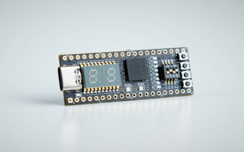
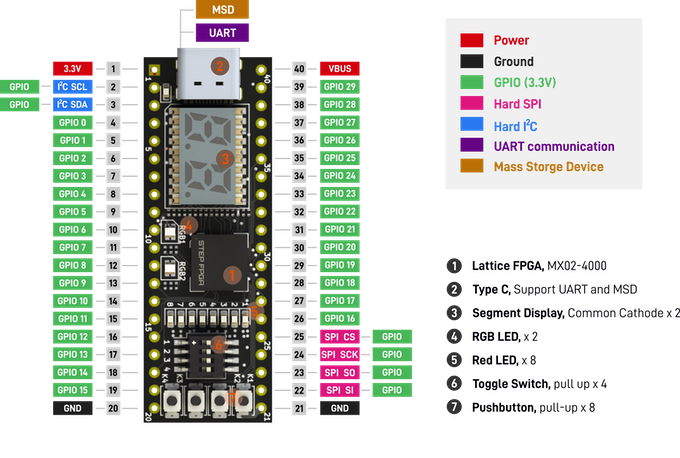
The miniature FPGA development board, the STEPFPGA MXO2Core is based on the Lattice MXO2-4000 FPGA chip. This chip is multi-purposeful and multi-functional as it incorporates features of both FPGAs and CPLDs (complex programmable logic devices). The chip’s built-in flash memory enables quick hardware configuration, which takes less than 10ms, while still incorporating 4000+ LUTs for moderate to commercial digital system design.
The board has 36 GPIO pins and by employing an internal phase-locked loop (PLL), the STEPFPGA MXO2Core’s clock frequency can be boosted from 12MHz to 400MHz. The MXO2Core board does not require the installation of any driver and takes only a few seconds to flash the chip. Additionally, the board also features a UART TX and RX module which aid in debugging with a serial COM port on your computer. The board also offers a block of RAM of 92 Kbit and a user flash of 64 Kbit.
The components of this delicate board are lead-free, and Kickstarter mentions that some of the “0201 footprints parts are just a bit thicker than your hair”. Made up of a four-layer PCB with immersion gold technology, the board features interactive components like LEDs, segment displays, switches, and push buttons allowing people to interact and examine outcomes in a tangible way. Furthermore, the DIP40 footprint offers you the option of expanding your projects on a breadboard or embedding the board in your projects.
The STEPFPGA MXO2Core board supports development on its Web-based IDE and Diamond IDE platforms. The user-friendly MXO2Core board facilitates the development of FPGA projects using the cloud-based IDE, Verilog which provides abundant pre-built examples and a simple interface. It is also compatible with the MacBook, Windows, and Linux operating systems.
Priced at $54.99, EIM Technology’s STEPFPGA MXO2Core board, also known as the STEP-MXO2, can be ordered from EIM’s Tindie store, with an expected delivery of the boards starting in July.
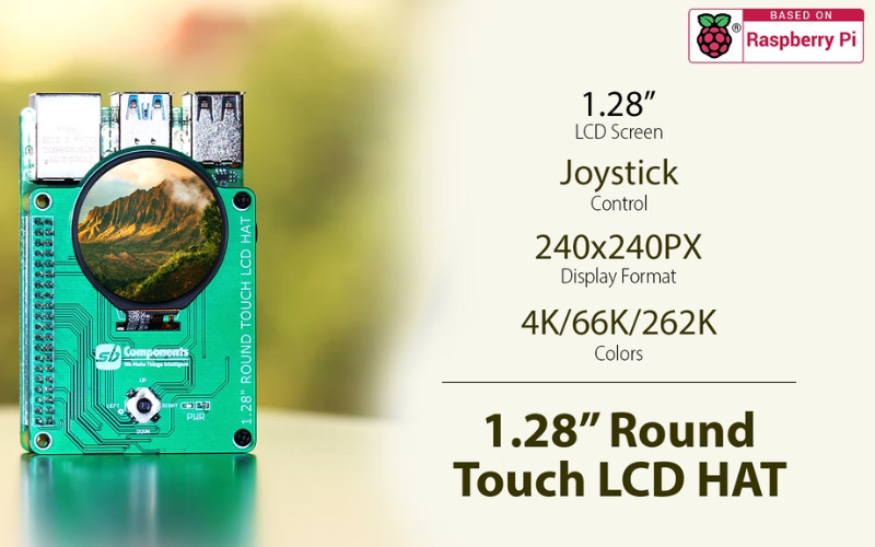
UK-based embedded device manufacturer, SB Components, has launched a crowdfunding campaign for a 1.28-inch touch LCD HAT with a goal of £3,000. The Kickstarter product page gives us more details on the 1.28-inch display, which has been over-subscribed to reach £3,522 (as of writing). This shows the community’s support to send the hardware into mass production, and the pledging options start at £38 to get the round-touch LCD HAT for your Raspberry Pi computer. The early bird £35 has been sold out, and interested people had to pledge to buy the expensive options.
At the heart of the SB Components 1.28-inch round LCD HAT is a capacitive touch control ICU with a high-performance self-capacitance touch clip. The LCD HAT has three main components as part of the hardware– a full-touch LCD display, a touch panel, and a joystick to move around for various actions. The full HD display has a resolution of 240×240 pixels and the 1.28-inch colour IPS TFT display panel has a GC9101A controller and panorama view angle. The touch panel is a capacitive screen with support for up to 13 sensing channels, and >100Hz refresh rate. The single-point gesture and two-point options are key highlights of the onboard touch panel.
Specifications of the 1.28-inch round touch LCD HAT:
Display: 1.28-inch TFT display
Resolutions: 240×240 pixels
Display connector: FPC
Color: 4K, 65K, 262K
Contrast: 500:1
Operating temperature: -22 to 70
LED lifetime: 30,000 hours
Interface: 4-wire serial SPI
Response time: 20ms
Power supply: 2.5V to 3.3V
The joystick can be seen below the display panel which is designed to provide comfort and ease while switching between different functions. It uses an SPI serial communication protocol to provide a unified platform through the standard 40-pin GPIO interface. The 5-input manual command is connected to the 1.28-inch round touch LCD HAT through a GPIO connector header. Some of the applications that can be developed using this SB Components’ 1.28 round touch LCD display HAT are weather broadcasting, security systems, home automation, multimedia applications, etc.
More details on the product are available on the crowdfunding product page. If you are interested in pledging the 1.28-inch round touch LCD display HAT, the product will be accepting pledges until July 9, 2022.
While negative feedback controls and corrects the behavior of a system, positive feedback encourages and strengthens the behavior of the system. For this reason, it is also known as regenerative feedback. Positive feedback generally occurs when the fed-back signal is in phase with the input signal and it causes the magnitude of the input signal to be increased i.e., it improves the overall gain of the system.
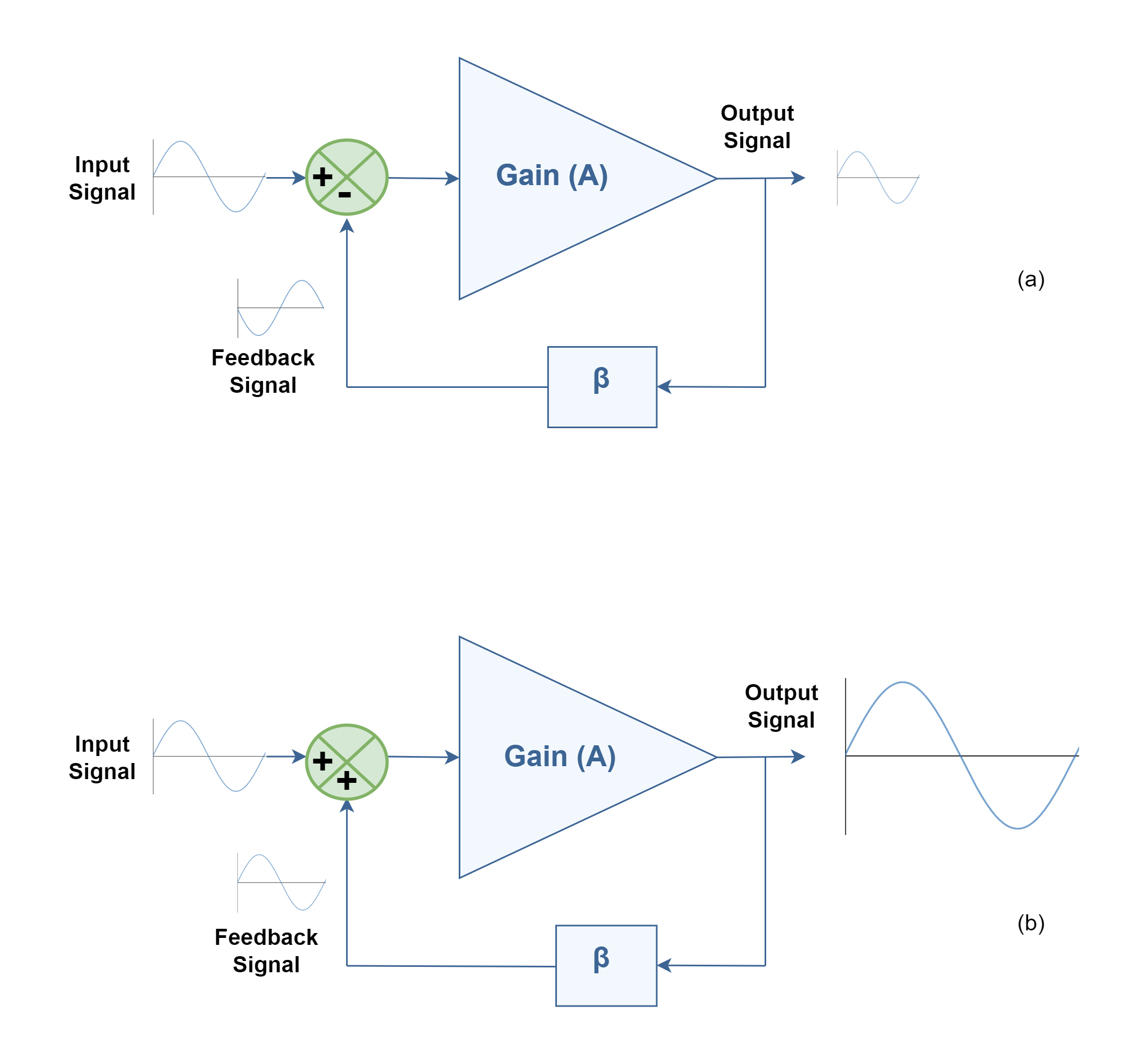
Figure 1 shows the difference between mechanisms of feeding output signal to the input terminal in the case of in-phase (positive feedback) and 180° phase-shifted (negative feedback) feeding signal. The main 2-port linear network, like an amplifier, has the open-loop gain of ‘A’ and the feedback network has the transfer function with the magnitude of ‘β’. Obviously, the feedback signal comes to the input terminal after a small delay time, and then it is combined with the input signal which is sketched here as a sinusoidal waveform.
Figure 1: Comparison of 2 types of feedback configurations containing negative feedback (a) and positive feedback (b)
A key feature of positive feedback is that small disturbances get bigger. When a change occurs in a system, positive feedback causes further change, in the same direction until the output gets as high as it can go. Under certain gain conditions, positive feedback reinforces the input signal to the point where the output of the device oscillates between its maximum and minimum possible states (upper- and lower- rails). Therefore, the amount of positive feedback allowed is typically very limited to cause only small changes to the input signal.
In practical domains, while negative feedback is often used to create controlled amplifiers and filters, positive feedback is seldom used in amplifiers, since it normally increases distortion and instability. However, the positive feedback mechanism is employed in oscillator circuits.
It should be noticed that there are also certain conditions in which positive feedback is not good for semiconductor junctions and can harm them by thermal runaway.
Positive Feedback In Op-amps
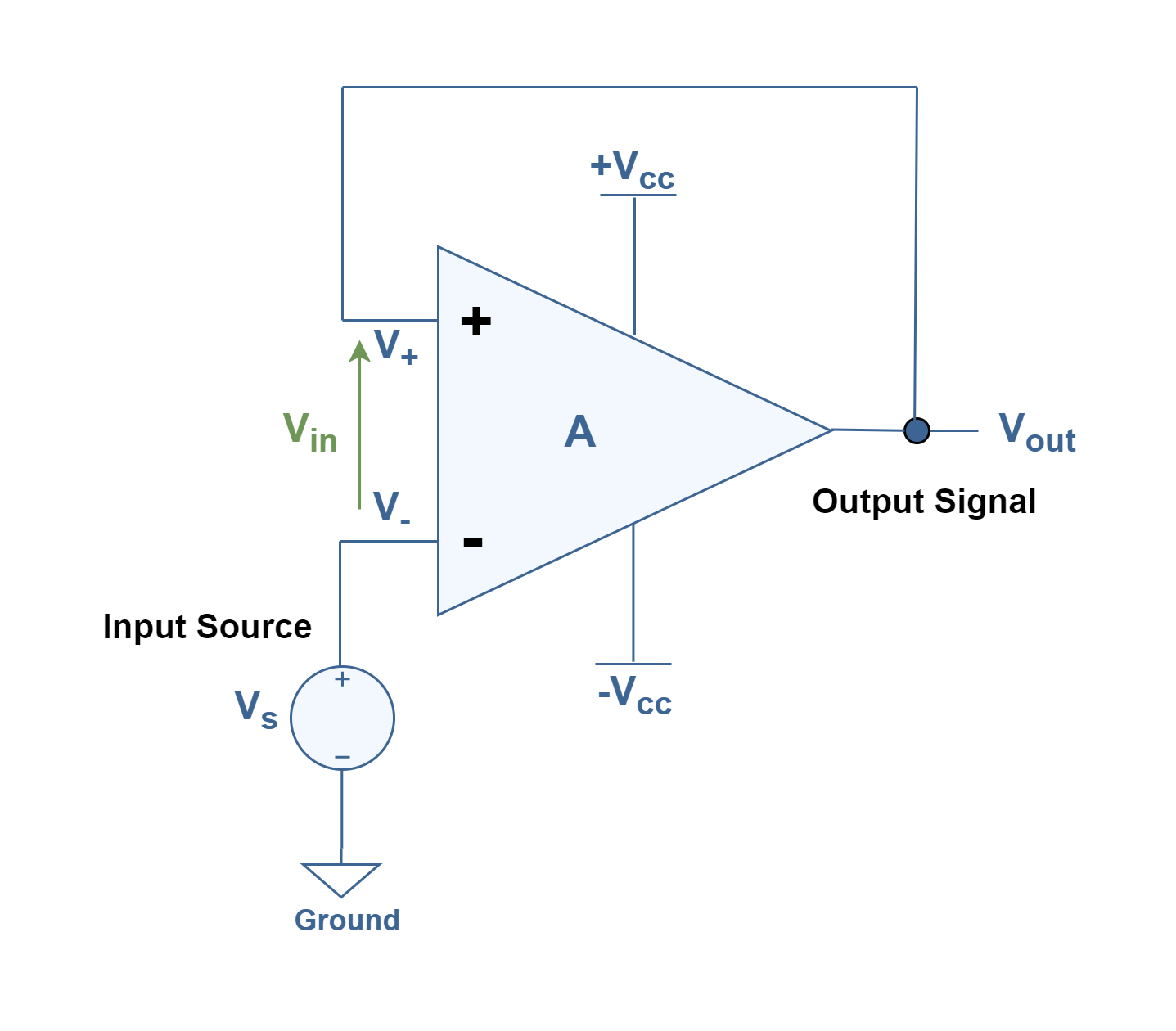
With positive feedback in Op-amp amplifiers, the feedback voltage to the noninverting input will drive the op-amp harder in the direction of the output generated signal i.e., toward saturation. Figure 2 shows the simplest schematic circuit of an op-amp positive feedback configuration by connecting directly the output terminal (Vout) to the noninverting input terminal (V+). In this arrangement, the external input voltage source (Vs) can be inserted at the inverting terminal (V–). Two positive and negative DC power supplies provide biasing of the op-amp.
Figure 2: An op-amp circuit with simple positive feedback
If the inverting input is grounded (maintaining V– terminal at zero volts by removing the input voltage source of Vs), the output voltage will be manipulated just by the magnitude and polarity of the voltage at the non-inverting input (V+). If this voltage happens to be positive, the op-amp will drive its output positive as well. Feeding that positive voltage back again to the noninverting input will result in positive output saturation which is equal to the positive power supply voltage of Vcc i.e., the upper rail. Thus:
Case 1: if V– = 0 and V+ > 0 then Vout = +Vcc
On the other hand, if the voltage on the noninverting input happens to become negative, the op-amp’s output will drive in the negative direction, feeding back to the noninverting input and resulting in full negative saturation (-Vcc or the lower rail). So:
Case 2: if V– = 0 and V+ < 0 then Vout = -Vcc
This simple analysis can be completed by applying input external excitation (Vs) and changing the voltage at inverting terminal (V–) and obtaining the same results. Therefore, what we have here is a circuit whose output is bistable; it means being stable in one of two states (saturated positive or saturated negative). Once it has reached one of those saturated states, it will tend to remain unchanged or latch in that state. By placing a voltage upon the inverting (V–) input with the same polarity, but with a slightly greater magnitude, the present state will be switched to the next.
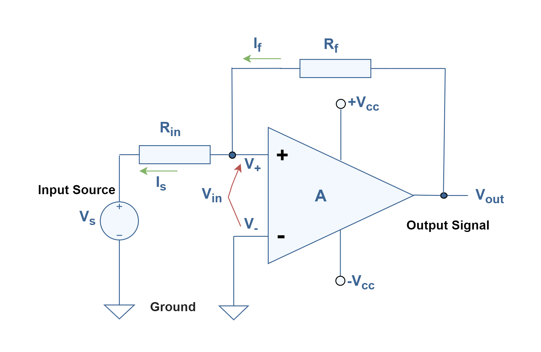
It is possible to have better control of the performance of this feedback system by adding 2 resistors between the input and the output terminals in the path of feedback. Figure 3 illustrates such a configuration by adding Rf and Rin to the op-amp and inserting an input voltage source (Vs) at the noninverting terminal (V+) while the inverting terminal (V–) is grounded.
Figure 3: Configuration of a positive feedback op-amp circuit as a comparator
One application of this circuit is a digital comparator, to convert a continuous analog signal to a two-state discrete signal. Also, by adjusting the size of the feedback resistor, a comparator can be made to experience what is called hysteresis. In effect, hysteresis gives the comparator two thresholds. By obtaining these thresholds, the comparator circuit becomes more immune to noise voltages that can produce unwanted swings in the output. The hysteresis causes the output to remain in its current state unless the input voltage undergoes a major change in magnitude.
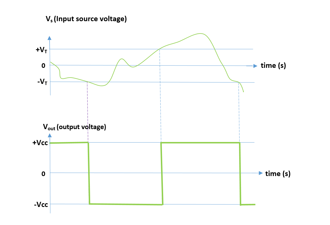
Figure 4 displays the amplitudewaveforms of the input signal (Vin) and the output signal (Vout) versus time. Vin is defined as the difference between noninverting and inverting voltages while:
Vin = V+ – V–
Figure 4: Waveforms of the input signal (Vs) and the output signal (Vout) versus time
To analyze the operation of the system we can first assume that the op-amp’s output is at positive saturation (+Vcc). Since V– is grounded, it is equal to 0 V. Because of the high impedance input characteristic of the op-amp, there is not any current inside the op-amp and the main current goes just through resistors of Rf and Rin. So, the two currents are equal; If = Is.
Using Ohm’s law:
If = (Vout – Vs) / (Rf + Rin)
By using the superposition principle, we first assume that Vs = 0, i.e., Rin is grounded. So:
Vin = Rin . If
The output remains at positive saturation (+Vcc). Now we assume that Vs has a non-zero value. If Vs is gradually reduced, there will be a point when Vin goes to 0 V, and the state of the output will be switched to another state (-Vcc). This voltage is called the negative threshold voltage (Vs = -VT) at the input. The negative threshold voltage can be determined by using the previous equations:
If = -VT / Rin = Vout / Rf = -Vcc / Rf
and then,
VT = Vcc (Rin / Rf).
Therefore, the width of the hysteresis region can be controlled by the ratio of the input and the feedback resistors. Now, if the output is at negative saturation (-Vcc) and 0 V is applied to the input (Vs = 0), Vin becomes negative and the output remains at (-Vcc). However, if the input voltage (Vs) is non-zero and it becomes increased, there is a point where Vin goes to zero, and the output switches states. This point is called the positive threshold voltage (Vs = +VT), which is equal to +Vcc. (Rin/Rf). In most applications, Rf is much larger than Rin.
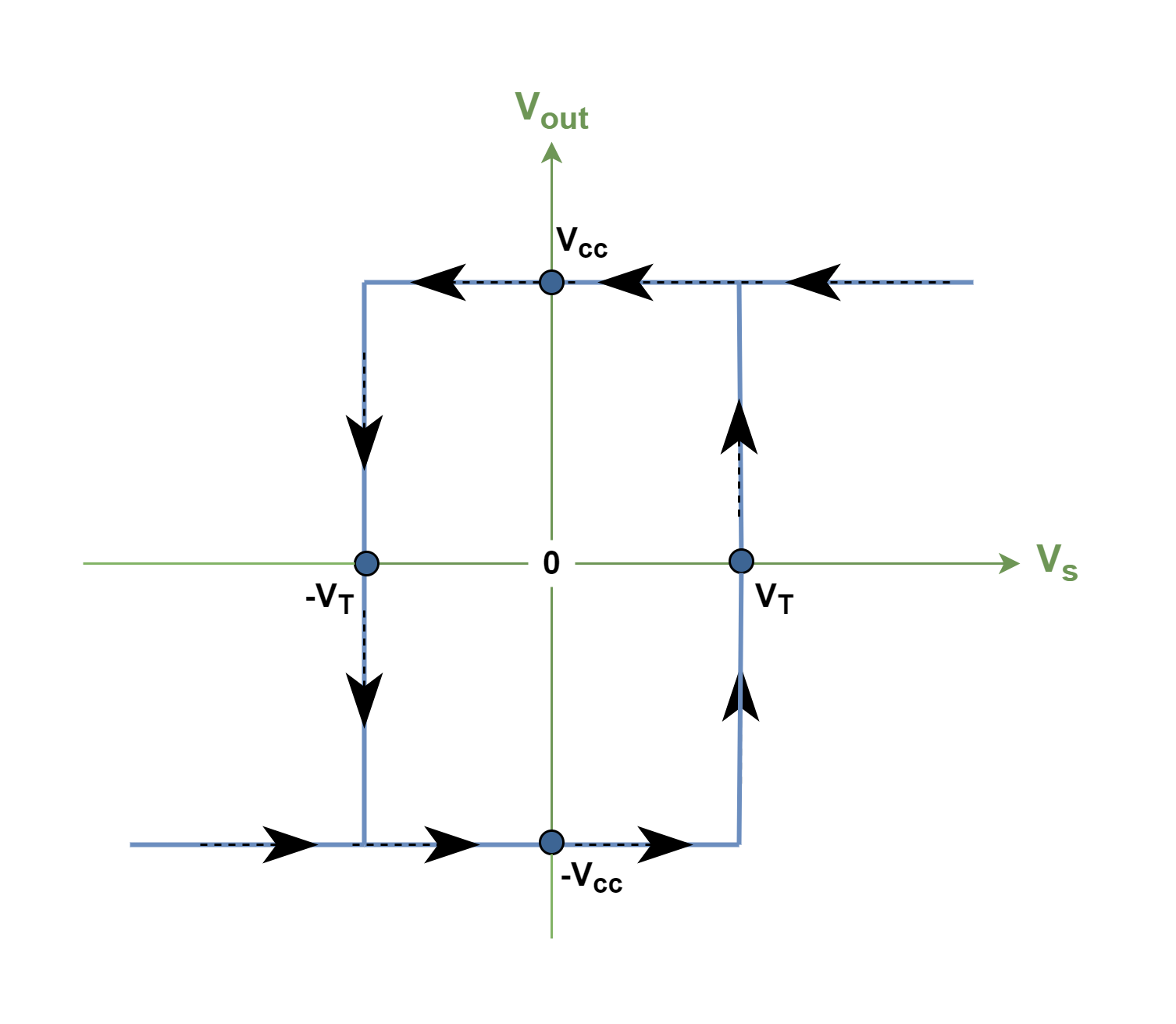
Figure 5 shows the relationship between the output saturation voltages and the margin of threshold voltages at the input. Arrows show the possible paths of changing the output voltage due to changes in the input source of voltage.
Figure 5: Hysteresis and threshold voltages in positive-feedback comparator
As Figure 4 shows clearly, applying a little positive feedback to the comparator and introducing threshold margins cause to extract of a clean square wave in the output, despite significant amounts of distortion and unwanted swings in the input signal.
The Oscillation Mechanism Of Feedback Networks
The advantages of feedback, however, are accompanied by corresponding disadvantages. Since the magnitude and phase of the gain of each network vary with frequency, it is probable in certain conditions to introduce sufficient phase-shift to cause positive feedback. Under these circumstances, the amplifier may become unstable and generate an output signal independent of the input (or without input signal); in other words, it oscillates unexpectedly.
The oscillation occurrence is mostly harmful in amplifier circuits and it is a disadvantage. But in applications like communication systems oscillators are advantageous and widely used in modulation circuits and timing applications.
For better understanding, it is important to notice the denominator in the basic negative feedback equation, Af = A/ (1 + βA). When βA= –1 or a magnitude of 1 at a phase angle of 180°, the denominator becomes 0, and the gain with feedback ‘Af’ mathematically becomes infinite or very high physically. Thus, a very small signal (like a noise voltage) can provide a measurable output voltage, and the circuit acts as an oscillator even without an input excitation.
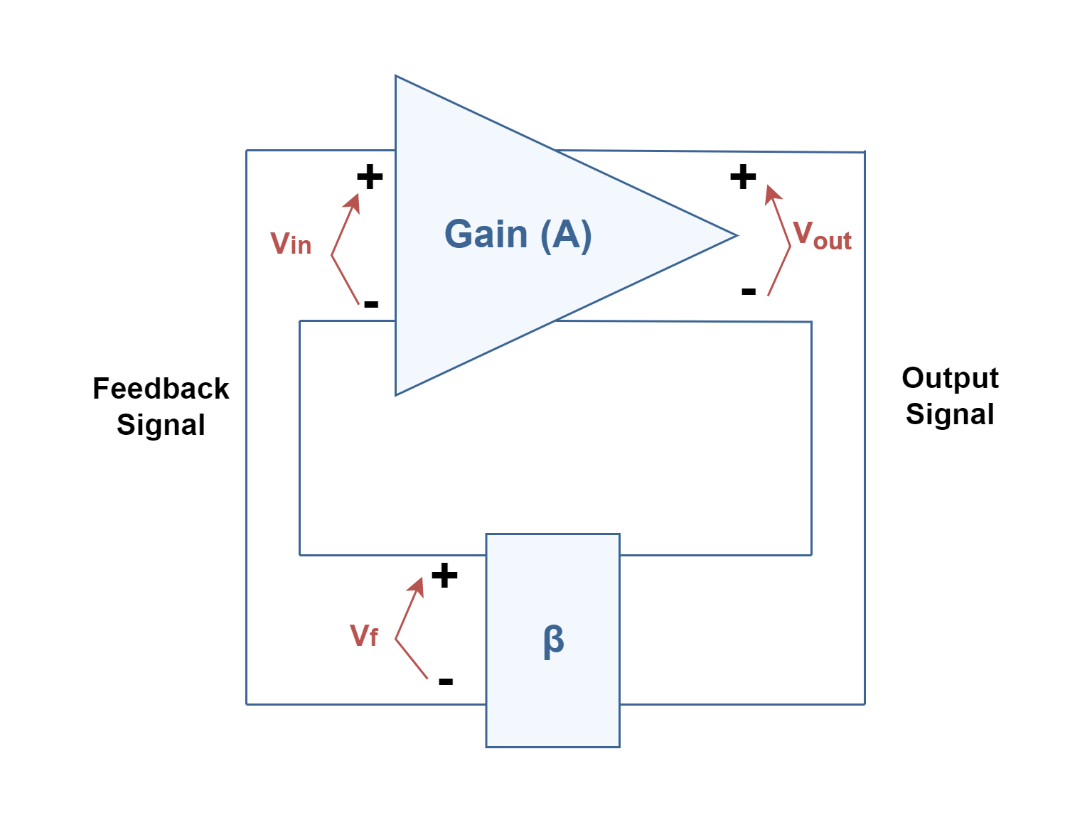
Figure 6 shows block diagrams of a general feedback system. If there is a fictitious voltage at the amplifier input ‘Vin’, it results in an output voltage of Vout = AVin after the amplifier stage and in a voltage Vf = β(AVin) after the feedback stage. Where βA is referred to as the loop gain.
Figure 6: A general feedback system without external excitation
If the circuits of the base amplifier and feedback network provide βA of a correct magnitude and phase, Vf can be produced equal to Vin. Then, when even the fictitious voltage Vin is removed, the circuit will continue operating since the feedback voltage is sufficient to drive the amplifier and feedback circuits. Therefore, the output waveform will still exist even without any input excitation, if the condition βA = 1 is met. This is known as the Barkhausen criterion for oscillation.
In practice, no input signal is needed to start the oscillator going. Only βA is made equal to or greater than 1 and the system is started oscillating by amplifying noise voltage, which is always present. Such oscillations are sometimes called parasitic oscillations.
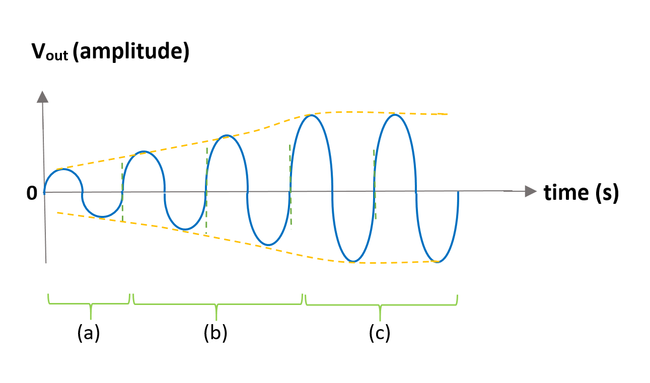
Figure 7 shows how the noise signal results in a buildup of a steady-state oscillation condition. In this waveform, three-section can be recognized: (a) In this period of time certain conditions are provided for an initial noise voltage to be amplified and appear at the output. (b) In the next period of time, this small non-sinusoidal signal (because βA is not perfectly 1) will be progressively gained in magnitude due to the positive feedback procedure. (c) the output waveform reaches a steady-state oscillation with a limited envelope due to circuit saturation conditions.
Figure 7: Generation of the periodic waveform due to oscillation in the circuit
Although positive feedback is useful in constructing oscillator circuits, unwanted oscillations render an amplifier useless. Furthermore, electronic circuits often contain unwanted but unavoidable feedback paths. The signals fed back through such paths can deteriorate performance. Similar effects caused by the stray or parasitic capacitance between the parts of an electronic component or circuit are sometimes observed.
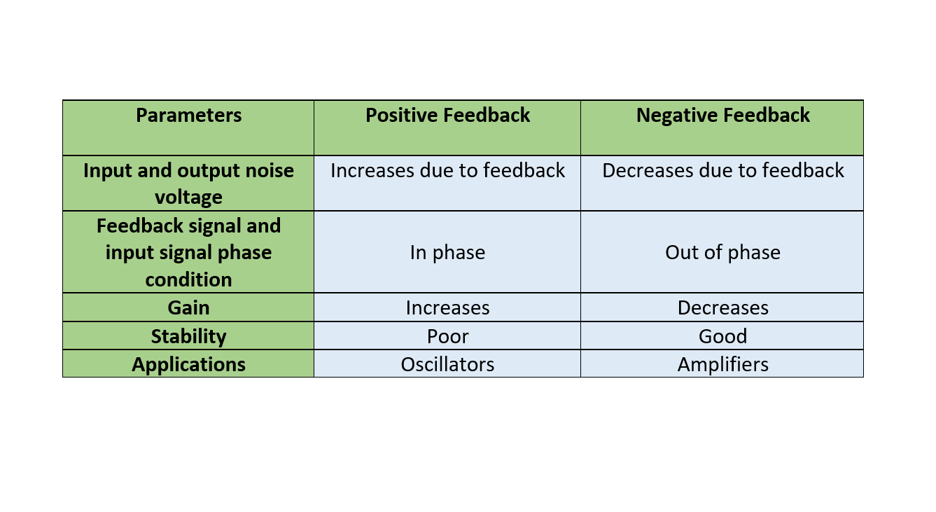
Finally, the features of negative and positive feedback systems are compared in Table 1.
Table 1: Comparison of positive and negative feedback systems
Summary
In electronics, there is the in-phase relationship between input and output in positive feedback, and the output is fed back to the positive input. This has the effect of increasing the output and going to extremes.
An op-amp with positive feedback tends to stay in the previous state of its output.
The hysteresis is an effect very commonly created using a positive feedback loop with an op-amp.
The use of positive feedback that may result in a feedback amplifier having loop-gain βA equal to or greater than 1 and satisfying the phase conditions will result in its operation as an oscillator circuit. An oscillator circuit then provides a periodic varying output signal.
Oscillators can be imagined as amplifiers with positive feedback.
The Hexadecimal (16) number is a base-16 numbering system that uses sixteen (16) numbers to represent its digit’s value. The hexadecimal number uses a group or set of four (4) binary digits to form a hexadecimal digit. In other words, a hexadecimal digit is equivalent to a nibble and we know, from the previous article, that a nibble is a four-bit binary number. The right-most nibble forms the least significant hexadecimal digit and nibbles can be added to the left of it to represent a larger hexadecimal number.
The architecture of digital systems is designed for 8, 16, 32, and 64-bit, etc. binary numbers and the presentation of these numbers in zeros (0) and ones (1) become quite confusing and complex. The reading and writing of larger binary numbers could lead to errors and information may become doubtful, indeed. The representation of larger binary numbers can be managed by using a higher base value numbering system which will accommodate more value in single-digit compared to the binary digit (bit). The octal (base-8) digit can use eight (8) numbers (0 to 7) and can accommodate a 3-bit binary number. The 3-bit binary number is quite small and not suitable for 8, 16, 32, and 64-bit architectures, etc. Likewise, the decimal number is suitable to represent a 3-bit binary number but wastes two (8 & 9) number values. In other words, an octal numbering system is more suitable compared to decimal (denary) numbers when it comes to representing binary numbers.
A suitable and appropriate numbering system is one that could accommodate a 4-bit binary number. As we know, a 4-bit number can hold sixteen (16) values (two raised to the power of four). This requires a numbering system having a set of sixteen values i.e. from 0 to 15. A digit of decimal has a range of numbers from 0 to 9 and above numbers such as 10, 11, 12, 14, and 15 cannot be represented as it involves the usage of previously used numbers. In hexadecimal, the values above nine (9) are represented by English alphabets such as A, B, and C, etc. Usage of these alphabets overcomes the problem of number repetition for ten (10) and above values.
This means A, B, C, D, E, and F in hexadecimal represent decimal numbers of ten (10), eleven (11), twelve (12), thirteen (13), fourteen (14), and fifteen (15). The same holds to represent equivalent binary numbers of “1010”, “1011”, “1100”, “1101”, “1110.” and “1111”, respectively. The difficulty of representing a larger binary number can be eased by splitting the binary number into groups of 4-bits. For example, consider (11011001110010102) which is a 16-bit binary number and the same can be written as (1101 1001 1100 10102). The latter is achieved by splitting into a group or set of 4-bits and the resultant binary number is much easier to read.
The length and complexity of binary numbers can further be reduced by converting them to equivalent hexadecimal numbers. However, hexadecimal numbers are complex compared to decimal numbers and are used only in digital systems. The 4-bit binary numbers “0000”, “0001”, “0010”, …, and “1111” are represented by a single hexadecimal digit. The 4-bit binary number is called a “nibble” which is equivalent to a hexadecimal digit. The byte is made up of 8-bits or two nibbles and as two hexadecimal digits represent such its equivalent. For example, the binary number (101001112) is split into two halves/ nibbles (1010 01112). Wherein, (10102) is equivalent to (1010) in decimal and to (A16) in hexadecimal. Similarly, the second nibble (01112), is equivalent to (7) in decimal and hexadecimal. So, altogether, the binary number (101001112) is equivalent to (A716) in hexadecimal.
Hexadecimal Numbers
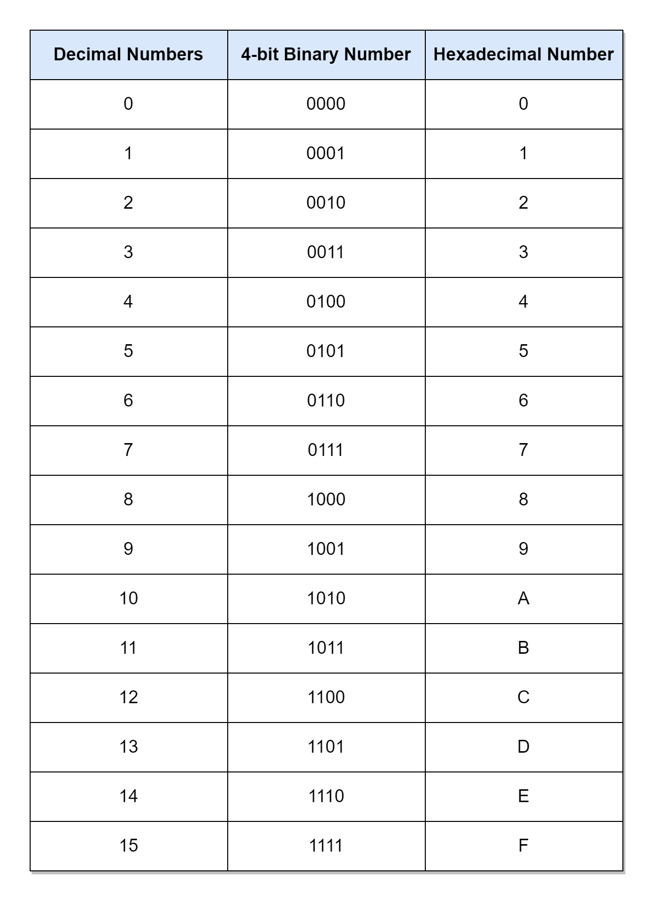
The following table lists the decimal numbers from 0 to 15 against their equivalents in binary and hexadecimal numbers.
The table above shows the equivalent decimal numbers from 0 to 15 for hexadecimal digits. For counting the numbers beyond fifteen (F) in hexadecimal, the procedure similar to other numbering systems is adopted i.e. including a significant digit to the left. For example, the “16” converted to binary is (0001 0000)2 and its equivalent hexadecimal is (1016). Similarly, the 17’s equivalent in hexadecimal is the (1116), and following the same procedure, the hexadecimal number can be extended to the desired value. Using the above table, any binary number can be easily converted to its equivalent hexadecimal number. For example, a 16-bit number (1010 1100 0111 10112) converted to hexadecimal is (AC7B16). It is much easier to write and remember this hexadecimal number than a 16-bit long row of 0’s and 1’s. Hence, it is a good practice to write binary numbers in a hexadecimal numbering system in order to avoid errors, etc.
In digital systems, especially when writing programs, a “#” (hash) sign is used after the most significant digit to denote the hexadecimal value. For example, the above hexadecimal number (AC7B16) can also be written as (#AC7B).
Counting in Hexadecimal
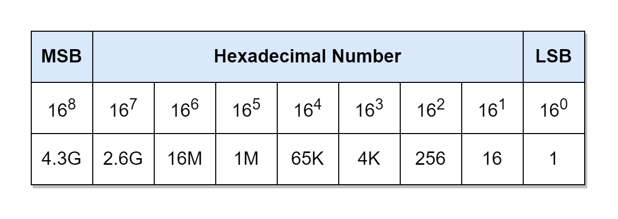
As described above, the value of a hexadecimal number can be extended by using additional significant digits. A single hexadecimal digit, starting from “0”, can count up to #F (15 X 160 = 1510) which extended to two digits can count up to #FF (15 X 161+15 X 160 = 25510). Similarly, #FFF and #FFFF can count up to 409510 and 6553510, respectively. The following table lists the weight of each digit in a hexadecimal number.
Addition of 0’s to a Binary Number
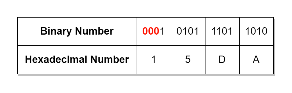
As the binary number is split into groups comprising of 4-bits in order to determine its equivalent hexadecimal number. This requires a binary number consisting of bits that are multiples of four (4) e.g. 4, 18, 12, 16, and 20, etc. However, this may not be the case when dealing with binary numbers and binary numbers can vary in bit lengths. The solution is to start splitting binary numbers, in groups of 4-bits, from the least significant bit (LSB), and, eventually, we will be left with less than 4-bits at the end. The leading zeros are added to leftover bits extending their length up to 4-bits. This group of 4-bits constitutes the most significant digit (MSD) of hexadecimal numbers. In the following table, a non-standard 13-bit binary number (1 0101 1101 101010) is converted to a 16-bit (divisible by 4) binary number by adding leading zeros, and then its equivalent hexadecimal number is determined.
In the above example, a 13-bit number requires 3-bits having zero values to be added to the left-most side in order to make it a 16-bit binary number. Similarly, a 10-bit binary number would require six (6) zero bits to be added. The usage of hexadecimal numbers reduces the length of binary numbers by four (4) times and conversion from binary to hexadecimal or from hexadecimal to binary is easy and quick.
Hexadecimal to Decimal Conversion
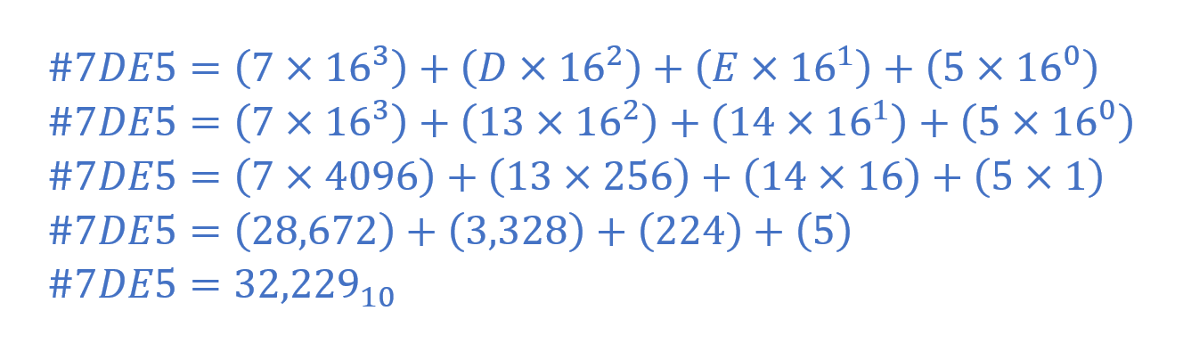
The conversion of hexadecimal to decimal value is achieved by using the weighted sum of digits method described in the previous article. In the following example, a hexadecimal number (#7DE5) is converted to a decimal number.
Decimal to Hexadecimal Conversion
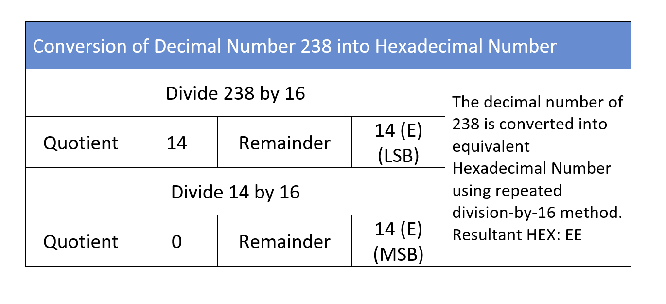
The conversion from decimal to hexadecimal requires the application of the repeated-division-by-16 method which was used to convert a decimal number to its equivalent binary value in the previous article. The same decimal number (23810) is used to obtain its equivalent hexadecimal number in the following example.
Binary to Hexadecimal Conversion Example
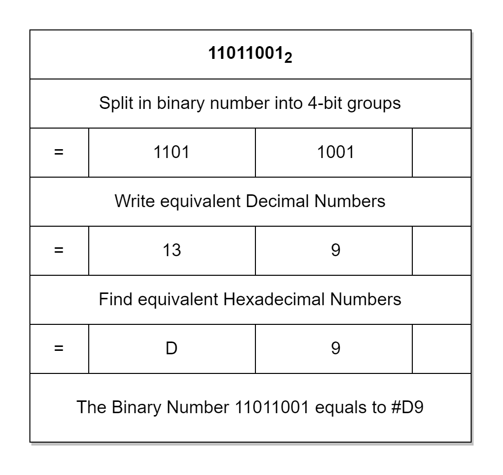
The conversion of an 8-bit binary number (110110012) to a hexadecimal number is shown below.
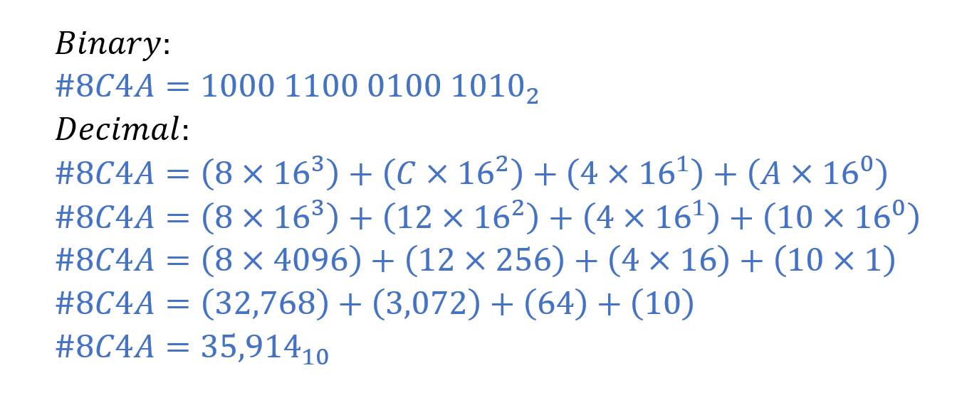
Hexadecimal to Binary and Decimal Example
The conversion of #8C4A to its equivalent binary and decimal number is shown below as an example.
Conclusion
The Hexadecimal number uses a base-16 numbering system and its digits can have sixteen (16) numbers from 0 to 15. In hexadecimal, the capitalized alphabets: A, B, C, D, E, and F are used as equivalent to 10, 11, 12, 13, 14, and 15, respectively.
In Hexadecimal numbers, each digit is a group or set of 4 bits. The equivalent of a binary number in hexadecimal is obtained by splitting the binary number into groups having 4 bits and then, depending on each 4-bit group’s value, an equivalent Hexadecimal value from “0” to “F” is assigned to each group.
The binary numbers may require the addition of leading zeros on the left most (most significant) side in order to form 4-bit groups.
The Hexadecimal number is represented by using “16” as a subscript or a hash (#) at the left-most side e.g. 2A7E16 or #2A7E.
The Hexadecimal number can be converted to a decimal number by using the weighted sum of digits method. The conversion from decimal to hexadecimal requires the application of the repeated-division-by-16 method.
The Hexadecimal numbers are useful in representing larger binary numbers. The Hexadecimal number reduces the length of its equivalent binary number by a factor of four (4). Moreover, the conversion from binary to hexadecimal and from hexadecimal to binary is easy and quick.
In 2017, VOOPOO acquired the American chip brand GENE. After that VOOPOO independently developed and created two types of gene chips called GENE.AI and GENE.TT that are used in their products. Below are some of their highlights.
GENE AI Chip
Artificial Intelligence
Smart chip, enjoy the interaction
Novice Friendly
Intelligent matching and precise control of power make the service time more lasting
Puff record, manage your suction life everywhere and every time
Automatic suction, suction has never been so simple
GENE AI, as the name suggests, means “artificial intelligence”. It aims to provide users with an intelligent and convenient experience, and supports “intelligent identification”, “intelligent power matching”, and “puff record”. GENE AI is primarily used in VOOPOO’s POD and POD MOD products. The two novel VMATE products we launched today are based on GENE AI.
Representative product:
VMATE E (the new product from VOOPOO)
GENE TT
Turbo Tech
Super explosive, multi-experience
Necessary for enthusiasts
In just 0.001 seconds, the ultimate second suction experience
In GENE.TT, “TT” is the abbreviation of “turbo tech”. Its core is to provide users with an experience of blasting power. Compared with GENE AI, GENE.TT is more professional, more playable, and more expansible. GENE.TT is primarily used in VOOPOO’s POD and POD MOD products. The three flagship products of ARGUS MOD FAMILY are based on GENE.TT.
Representative product:
VOOPOO ARGUS GT 2 (the product which has won the title of “BEST MOD” for many times)
Author: Marian Hryntsiv, Senior Technical Documentation Apps Engineer, Renesas Electronics
1. System Overview
Nowadays, humidifiers have become popular devices. They are frequently used to increase the level of humidity in rooms in many houses across continents. Ultrasonic humidifiers use a piezoelectric transducer to create a high-frequency mechanical oscillation in a water film. This forms an extremely fine mist of droplets, about one micron in diameter, that is quickly evaporated into the airflow.
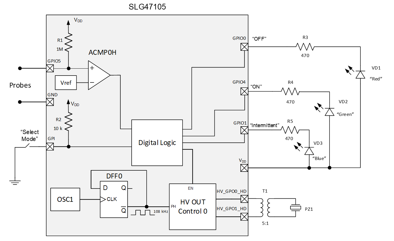
SLG47105 can be used to implement the basic functionality of the ultrasonic humidifier (see Figure 1).
Figure 1. General Schematic of Ultrasonic Humidifier Based on SLG47105
In this article, the piezoelectric transducer with a resonant frequency equal to 108 kHz is used. SLG47105 has an oscillator OSC1 with a flexible divider, which allows to accurately set the desired frequency.
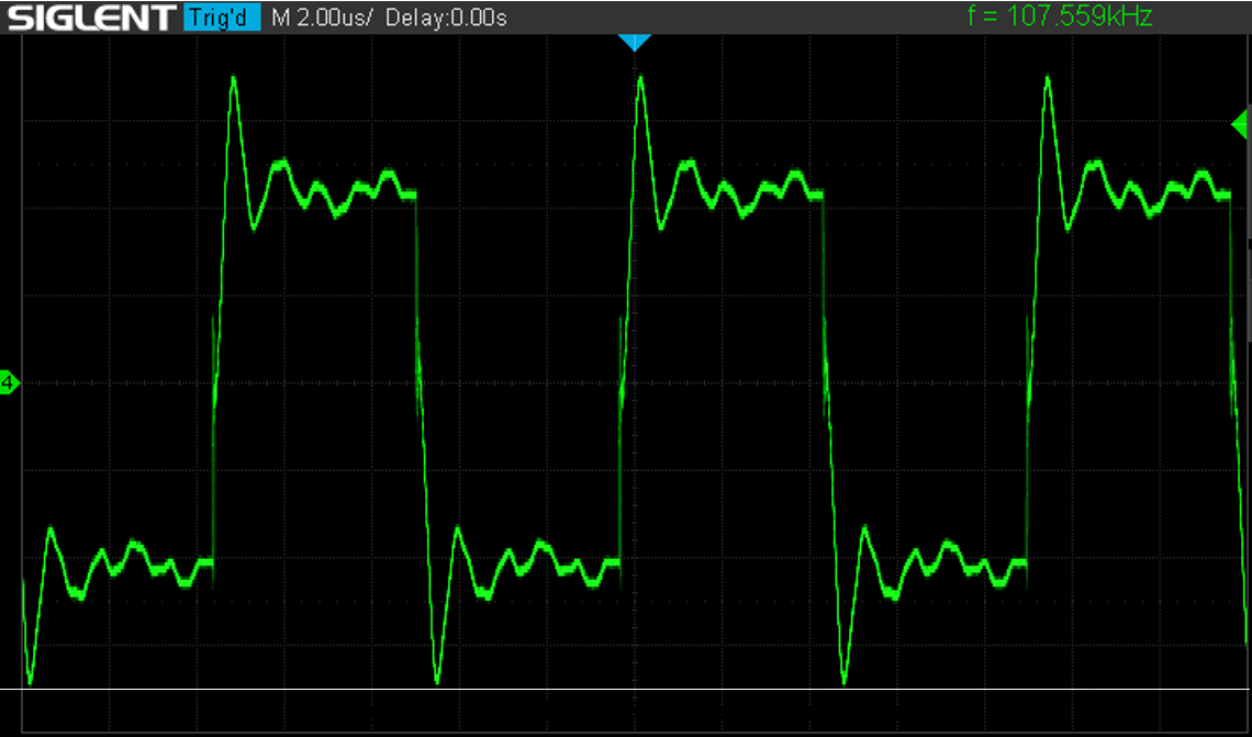
Figure 2. Signal between Transformer Inputs
Additionally, D Flip-Flop (DFF0) is used to get a 108 kHz clock signal from the oscillator’s output signal. HV_GPO0_HD and HV_GPO1_HD are high voltage and high drive pins that allow to get the desired output power (see pins output signal in Figure 2). A transformer has a turns ratio of 5:1. It allows getting from 5 V the required voltage for the operation of the piezo converter.
2. GreenPAK™ Design
Figure 3 shows an internal design of the project created in GreenPAK Designer software (a part of Go Configure™ Software Hub). The complete design file can be downloaded here
Figure 3. GreenPAK Designer Project
2.1 Humidifier Modes of Operation
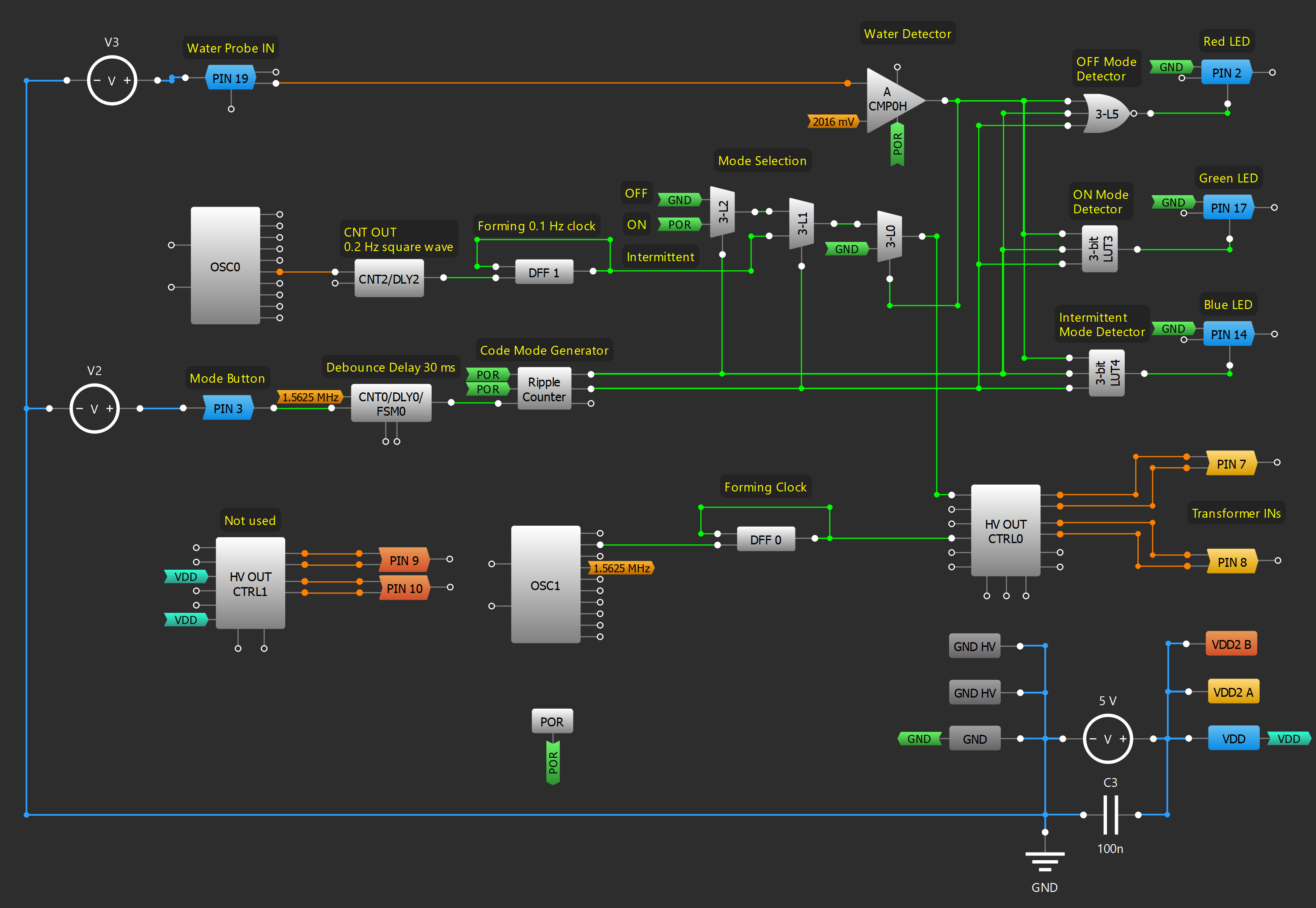
For flexibility in use, the humidifier has three modes of operation: OFF state, ON state, and intermittent operation. The last mode means that the humidifier works for 5 s and then waits for 5 s, and so on alternately. Digital logic macrocells were used to implement these modes. An external button is used to select a mode of operation. It produces noisy output oscillations due to switch bouncing. To eliminate that noise 30 ms delay is used. With every pressing of the button, Ripple Counter generates a digital code for the appropriate mode. There are three modes of work and, respectively, three digital codes: 00, 01, 10. The output signal from Ripple Counter goes to select inputs of cascaded multiplexers (3-L1 and 3-L2) and thus allows to choose which signal will pass to the output: LOW level signal (OFF mode), HIGH level signal (ON mode), or clock signal with frequency 0.1 Hz (Intermittent mode). And, if there is water inside the humidifier, multiplexer 3-L0 allows passing one of the signals from cascaded multiplexers on the Enable input of the HV OUT Control macrocell.
For Intermittent mode, Reset Counter2 and DFF1 form a 0.1 Hz clock signal.
LEDs indicate mode of operation: red LED – OFF mode, green LED – ON mode, blue LED – Intermittent operation. LUT3, LUT4, and LUT5 detect each mode and turn on the corresponding LED with the help of pins. Pins work as 3-state outputs. When a HIGH level signal appears on the pin’s Output Enable input then the pin goes from a high impedance state to a logic 0 state. This LOW-level signal causes the corresponding LED to turn on. For a more advanced experience, when the humidifier is in OFF mode, it can be used as a night light with a red glow.
2.2 Water Level Detection
One of the negative features of ultrasonic humidifiers is that the piezoelectric disc can be destroyed if the humidifier runs out of water. That’s why it is very important to implement an automatic shut-off of the humidifier when the disc is dry. In this project, probes immersed in water were used. When there is no water between the probes, an analog comparator’s output is HIGH, which disables high voltage pins and stops piezo disc oscillation.
3 Humidifier Prototyping
The humidifier developed in this project can replace a finished product on the market. For this purpose, a portable ultrasonic humidifier was bought and analyzed (see Figure 4).
Figure 4. Ultrasonic Humidifier General View
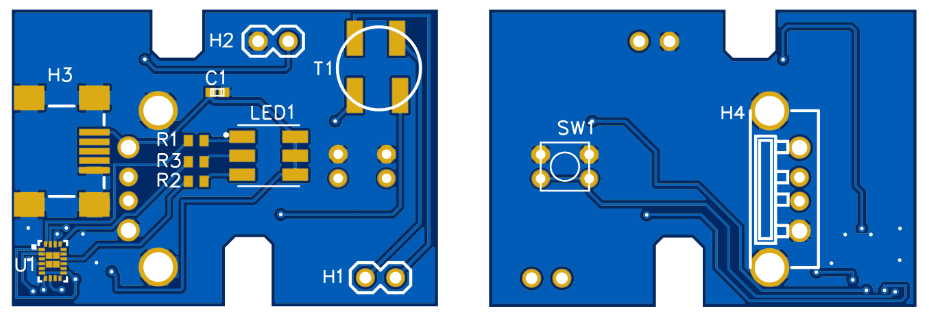
The dimensions of the PCB and the location of the main components of interaction with the user were measured. Based on these data, the PCB for the SLG47105-based humidifier was developed (see Figure 5).
Figure 5. Humidifier PCB Top and Bottom View
The humidifier based on the SLG47105 has some advantages over the purchased humidifier because it has water level detection. This function is very important because it can prevent the humidifier from failing. In addition, the number of electronic components has been reduced when using SLG47105.
4. Conclusions
The SLG47105 has two high drive H-Bridges, which can be used as four Half Bridges or two Full Bridges. One of the Full Bridges is used in this project to drive the ultrasonic piezoelectric disc. Its resonant frequency is set by the oscillator and flexible divider. This allows the piezoelectric disk to oscillate and form cool fog. Additionally, the availability of many versatile digital macrocells made it possible to add some additional features, like detection of no water, backlight control, and three operation modes. This design can be a functional replacement for popular standard portable ultrasonic humidifiers. Furthermore, GreenPAK is a cost-effective solution, which allows for minimizing components count and board space.
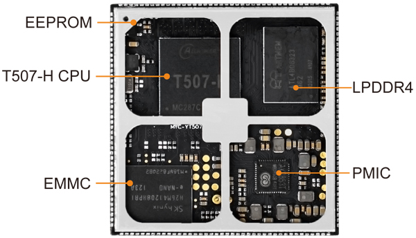
MYIR introduces a cost-effective MYC-YT507H CPU Module powered by ALLWINNER’s T507-H industrial processorwhich among Allwinner T5 series with a 1.5GHz quad-core Cortex-A53 CPU and a Mali-G31 MP2 GPU. The module is ready to run Linux OS and targets a wide variety of applications like power IoT, automotive electronics, commercial display, industrial control, medical devices, intelligent terminals and more other professional or industrial applications which require rich performance and professional visual effect.
Measuring 43mm by 45mm, the MYC-YT507H CPU Module is a compact System-on Module (SoM) that combines the Allwinner T507-H processor, a dedicated Power-Management IC AXP853T also from Allwinner, 1GB/2GB LPDDR4, 8GB eMMC and 32Kbit EEPROM. A number of peripherals and IO signals are brought out through 1.0 mm pitch 222-pin stamp-hole (Castellated-Hole) expansion interface to make the module an excellent embedded controller for system integration.
MYD-YT507H Development Board Top-view (delivered with shieldinig cover by default)
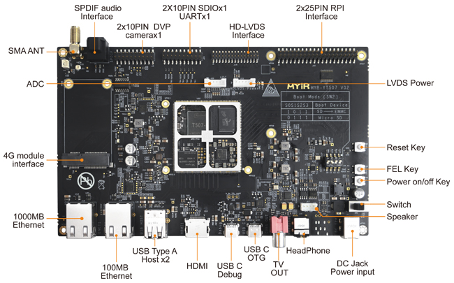
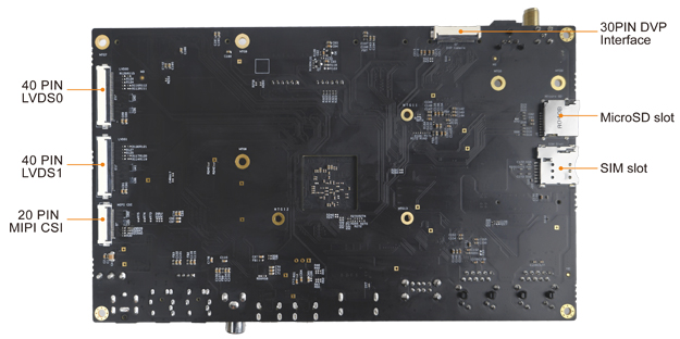
MYIR provides theMYD-YT507H Development Board for evaluating the MYC-YT507H CPU Module, its base board has explored a rich set of peripherals and interfaces such as Serial ports, one Gigabit Ethernet and one 10/100M bps Ethernet, two USB 2.0 HOST and one USB 2.0 OTG, one TF card slot as well as a USB based 4G Mini PCIE interface. It has a DVP camera interface and a MIPI-CSI interface to allow connecting with camera modules. It also supports multi video output interfaces such as dual LVDS, HDMI and CVBS OUT, to achieve different display in dual screens. The board is delivered with necessary accessories, detailed documentations as well as optional MY-CAM002U USB Camera Module, MY-CAM011B DVP Camera Module, MY-CAM003M MIPI Camera Module, MY-WIREDCOM RPI Module (RS232/RS485), MY-WF005S WiFi/BT Module and MY-LVDS070C LCD Module, which makes it ideal for evaluating and prototyping based on ALLWINNER’s T507-H processor.
MYD-YT507H Development Board Bottom-view
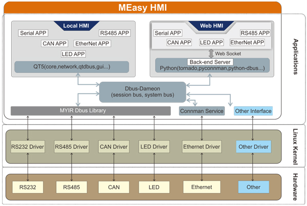
The MYC-YT507H Module is ready to run Linux OS. MYIR provides abundant software resources for Linux 4.9 based MYIR MEasy HMI V2.0 system with QT5.12.5, Ubuntu 18.04.5 system, including kernel, driver source codes and compilation tools to enable users to start their development rapidly and easily.
MEasy-HMI System Structure
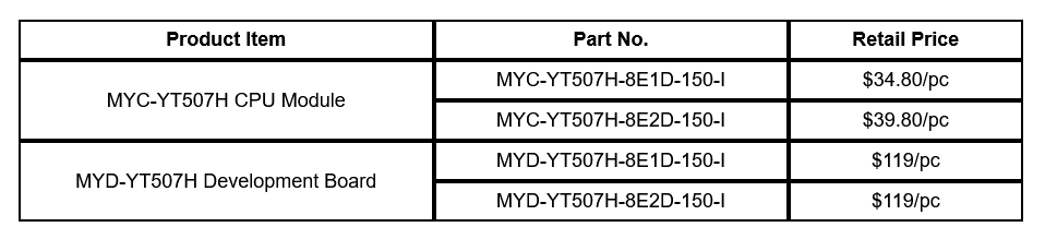
MYIR offers RAM options for CPU Modules and Development boards. The prices are economic. Discount is to be offered for volume quantities.
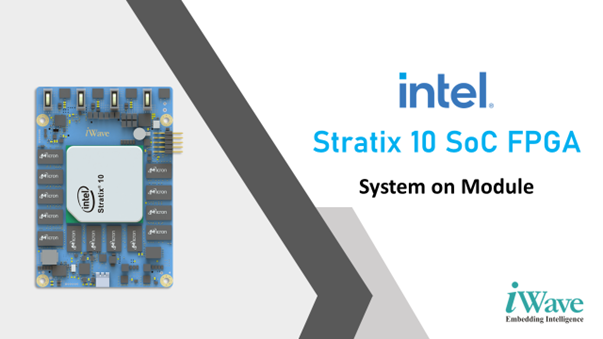
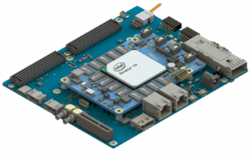
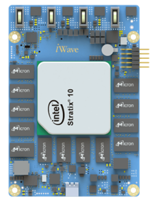
iWave Systems unveils the first look of Intel® Stratix® 10 powered System on Module at embedded world 2022. The System on Module is compatible with the SX and GX series of Stratix 10 SoC and FPGA, and is available in a form factor of 110mm x 75mm.
Stratix 10 brings about a revolutionary Intel® Hyperflex™ FPGA Architecture delivering the embedded performance, adaptability, power efficiency, density, and system integration essential for a broad range of high-performance embedded applications. Featuring a hard processor system (HPS) with an integrated 64-bit quad-core ARM Cortex-A53 processor with a feature-rich set of peripherals such as a system memory management unit, external memory controllers, and high-speed communication interfaces.
The Stratix® 10 Stems on Module provides for up to 2.7 million logic elements in a monolithic die, up to 48 transceivers deliver 4X serial bandwidth over the previous generation, Hard floating-point DSP enables single-precision operations up to 9.2 TFLOPS. The System on Module is compatible with GX850 to GX2800 and SX850 to SX2800 with a form factor of 110mm x 75mm.
Key Features of the Module
Compatible Stratix 10 SoC and FPGAs
SX850, SX1100, SX1650, SX2100, SX2500 & SX2800
GX850, GX1100, GX1650, GX2100, GX2500 & GX2800
Quad ARM Cortex -A53 Core @ 1500MHz
32GB eMMC & 1Gbit QSPI Flash
2 x 8GB DDR4 for FPGA (64bit + 64bit) (Upgradable)
8GB DDR4 for HPS with ECC (64bit + 8bit) (Upgradable)
Up to 2753K Logic Cells
16 GXT Transceiver Channels up to 28.3Gbps
32 GX Transceiver Channels up to 17.4Gbps
100 LVDS/200SE FPGA Ios
On SOM Clock Synthesizer
Form Factor: 110mm x 75mm
Stratix® 10 SoCs and FPGAs are built using Intel’s 14nm Tri-Gate transistor technology, offering next-level flexibility and user-selected configuration control with the Secure Device Manager (SDM), which provides security to protect sensitive intellectual property (IP) and data in both SoC and FPGA devices. This level of security makes Stratix 10 FPGAs and SoCs an ideal solution for use in military, cloud security and IoT infrastructure, where multi-layered security and partitioned IP protection are dominant.
“Embedding the high-performance Stratix 10 GX FPGA or Stratix 10 SX SoC into a compact SOM helps in providing high versatility for the Transceiver and FPGA capabilities” said Ahmed Shameem M H, Hardware Project Manager at iWave. “It also helps in drastically reducing the design and development time required for intelligent and complex FPGA solutions.”
Target markets of Stratix® 10 include HPC & analytics, acceleration, prototyping, high-speed communications, motion control, intelligent vision & video processing, digital signal processing, AI & deep learning, and many more.
The Stratix® 10 development kit delivers a complete design variable that includes all software and hardware which can be used to evaluate device features and performance, and also to begin the development of hardware and software design.
iWave provides for custom design and manufacturing services around the Stratix® 10 SoC FPGA System on Module, offering all of the hardware, software, and support materials offering a jump-start for application and product development with the Stratix® 10 GX/SX FPGA.
iWave Systems is an established product engineering company focused on the design and development of a wide range of powerful and flexible FPGA solutions. With over 22 years of diverse experience in the FPGA domain and a strong design-to-deployment competence, iWave strives to transform your ideas into time-to-market products with reliability, cost, and performance balance.
Last year, the Raspberry Pi Foundation announced a new microcontroller board equipped with an in-house RP2040 microcontroller– Raspberry Pi Pico. The hardware platform is one of the most famous Raspberry Pi microcontroller-class products that have reached over two million sales. RP2040 has also seen massive adoption with several manufacturers wanting to integrate the microcontroller SoC into their custom development boards. One of the reasons Raspberry Pi Foundation thinks of the huge success of RP2040 is the elimination of the supply chain problem. With the growing semiconductor shortages, several microcontrollers are out-of-stock, but this does not stop developers and makers from developing next-gen applications. The Raspberry Pi Foundation also announced the commercial availability of the RP2040 microcontroller for sale.
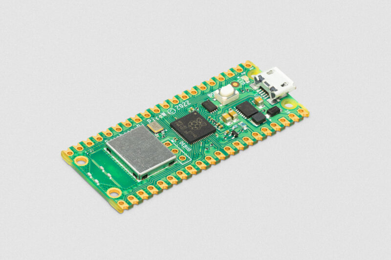
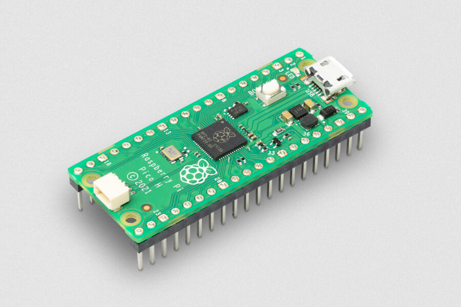
The company witnessed immense success with the first-in-the-line Raspberry Pi Pico module. With the increased adoption and continuous tweaking for the module to be in-line with the growing edge device needs, Raspberry Pi Foundation finally released a new Pico family product with wireless networking– Raspberry Pi Pico W. The name seems very similar to the Raspberry Pi Zero W, wherein the hardware is an extension of the Pi Zero family with added wireless LAN and Bluetooth connectivity. Following the same naming standard, Raspberry Pi Pico W will now be available for sale starting at $6.00 USD. Alongside the Raspberry Pi Pico W, the manufacturer has also decided to reveal more versions of the hardware platform, depending on customer requirements. Other versions include the Pico H for $5.00 USD and Pico WH for $7.00 USD with pre-populated headers and 3-pin debug connector. Raspberry Pi Pico H and Pico W will be available for sale starting today, while Pico WH will be available starting August 2022.
Raspberry Pi Pico H
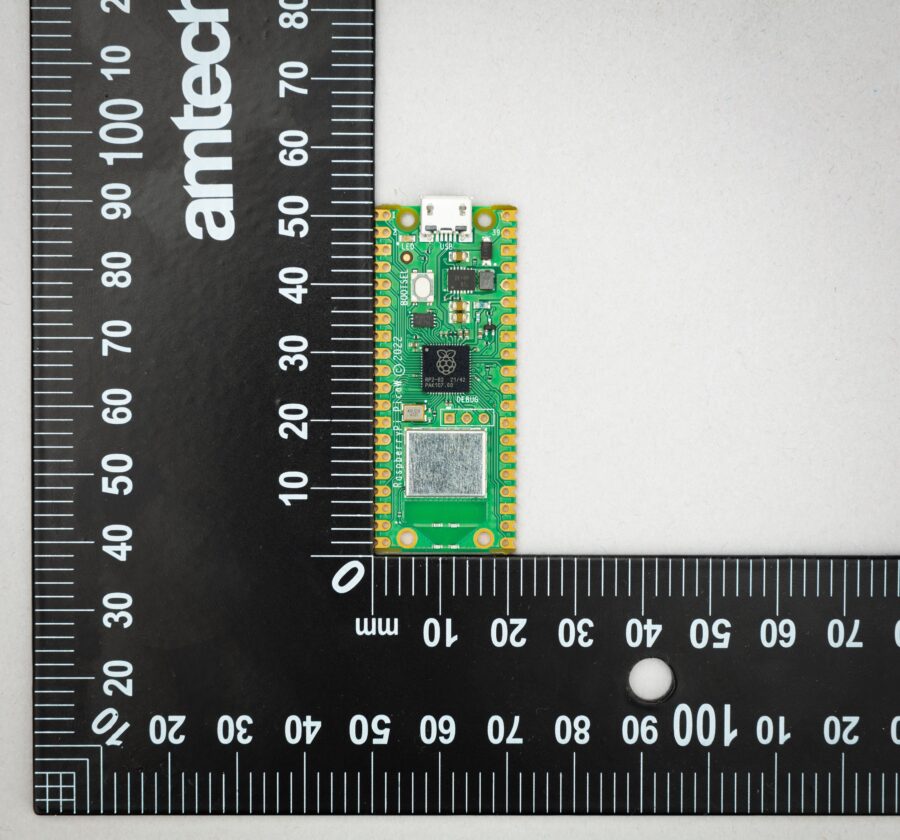
When it comes to the internal components for the all-new Raspberry Pi Pico W module, the Raspberry Pi Foundation has decided to stick with the original RP2040 microcontroller featuring Arm Cortex-M0+ processor core clocked at a frequency of 133MHz and a 264kB of on-chip SRAM and programmable IOs. Other than the basic SMT components and LEDs, the key highlight of the Raspberry Pi Pico W is the wireless networking capabilities leveraging the onboard Infineon CYW43439 wireless chip. However, if you carefully look at the CYW43439 module, the chip supports Wi-Fi 802.11n 2.4GHz wireless interface and Bluetooth Classic and Bluetooth Low-Energy. The manufacturer has clearly mentioned that the current Raspberry Pi Pico W hardware won’t be enabled for Bluetooth wireless connectivity, but the developers and makers can expect the manufacturer to do so in the near future.
Raspberry Pi Pico W will offer wireless LAN support along with an onboard antenna and modular compliance certification. The hardware will be able to operate in both station and access-point modes. Complete access to the network functionality is available to both C and MicroPython developers, giving them the flexibility to choose between the software environments. On the storage side, the Raspberry Pi Pico W paired with RP2040 will come with 2MB of flash memory, a power supply chip to support voltages from 1.8V to 5.5V and provide 26 GPIO pins with three for analogue inputs. The supported peripherals are UART, SPI, I2C, PWM and a UBS1.1 controller and PHY along with an 8x programmable IOs state machine. Also, the company promises to keep the production of Raspberry Pi Pico W until at least January 2028, which is approximately eight years from now.
The software documentation for the Raspberry Pi Pico W is very interesting as the Raspberry Pi Foundation has also released the Pico SDK which includes wireless networking support. The network stack is built around the IwIP and also uses libcyw43 from Damien George to communicate with the wireless chip. The libcyw43 is licensed for non-commercial use, however, with Raspberry Pi Pico W, users can build applications benefiting from a free commercial use license. The Raspberry Pi Pico SDK provides headers, libraries and build systems necessary to write programs for the RP2040-based Raspberry Pi Pico W hardware in C, C++ and/or assembly language. The SDK provides an API and programming environment for both non-embedded C developers as well as embedded C developers. A single code can run on the device at a time and starts with a conventional main(). Additionally, the Raspberry Pi Pico SDK also provides higher-level libraries for dealing with timers, synchronization, USD, and multi-core programming along with other utilities.
There are several interesting things about to happen with Raspberry Pi Pico W at $6.00 USD, and stay tuned with us for more updates. Meanwhile, you can consider purchasing the hardware from the official product page as well as look for detailed documentation for more information.
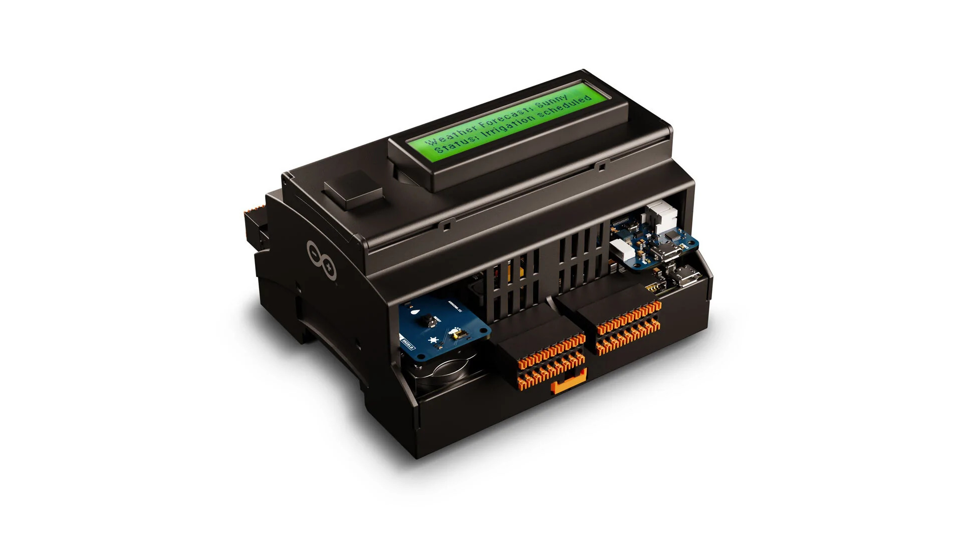
After more than a year of Arduino Edge Control introduction, the team has unveiled an enclosure kit, which is IP40-certified and compatible with DIN rails, to make it easy to fit into any standard rack. The edge control enclosure kit will be operating at industrial temperature ranges of -40°C to +85°C and does not require any external cooling system. The cover is IP40-rated which means it protects the edge control against solid objects of over 1 mm. Also, the enclosure kit includes a breakout board with an LCD display and a push-button so that the developer can use this to display data in the 2×16 LCD display and interact through the push-button.
Arduino Edge Control is designed for precision farming, smart agriculture, and other applications that require intelligent control in remote areas. Hardware supports power to be supplied through solar panels and DC inputs. The hardware platform can be controlled using Arduino Cloud or third-party services of your choice for various connectivity options. Arduino Edge Control features built-in Bluetooth wireless connectivity and other options can be expanded with 2G3/3G/CatM1/NB-IoT modems, LoRa, Sigfox, and Wi-Fi by adding MKR boards.
Specifications of Edge Control Enclosure Kit:
Type: Arduino Edge Control Enclosure Kit
Standard: IP40-certified
Mounting system: DIN rail
Operating temperature: -40°C to +85°C
Weight: 165 grams
Dimensions: 11x9x6 mm
Breakout:
LCD: 2×16 pixels
Button type: Push-button
Flat cable: IDC cable wires both display and push-button
Arduino Edge Control comes with an nRF52840 microcontroller featuring Arm Cortex-M4F clocked up to a frequency of 64MHz. The integrated memory is 1MB onboard flash and 2MB onboard QSPI flash memory with an interface for SD card connector through expansion port only. The peripherals include full-speed 12Mbps USB, Arm CryptoCell CC310 security subsystem, high-speed SPI, quad SPI interface, ADC, and 128-bit AES co-processor.
Arduino Edge Control enclosure kit is available for purchase at $54.00 and more details are available on the official product page.