Introduction
According to Norbert Wiener, the American mathematician and the father of cybernetics, feedback is a method of controlling a system by reinserting the results of its past performance into it. In a feedback system, a signal that is proportional to the output is fed back to the input and combined with the input signal to produce the desired system response. Harold Black, an American electrical engineer, invented the negative feedback amplifier in 1927.
Feedback comes in two varieties: positive, and negative. Negative feedback is a connecting technique where some of the output signal (e.g. voltage) is sent back to the inverting terminal and then it is added to the input signal there. It means the signal fed back from the output to the input is 180° out of phase with the applied excitation in the input. This feedback signal can be “sent” back through a resistor, capacitor, complex circuit, or simply through a wire.
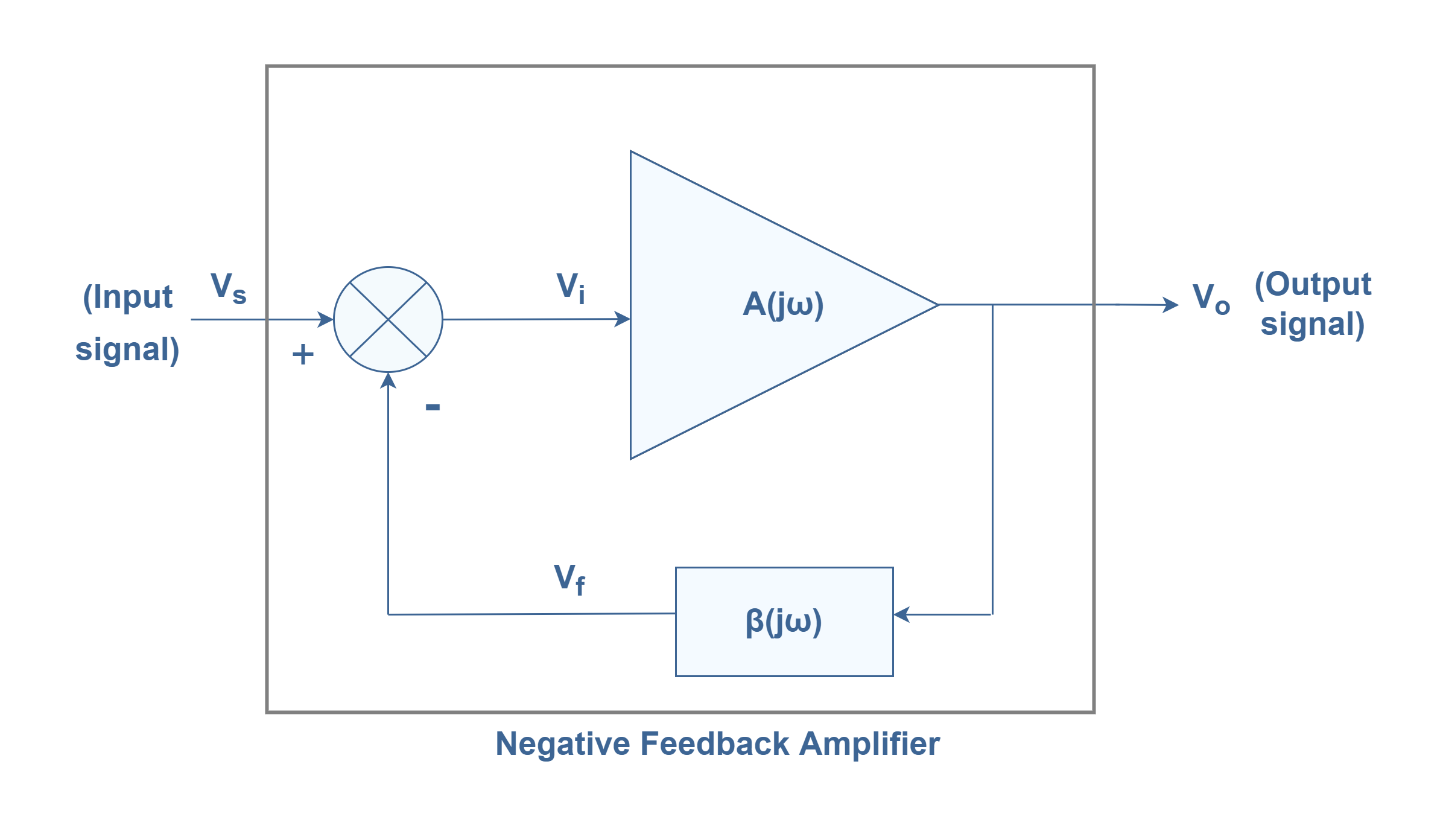
A typical feedback block diagram is shown in Figure 1. The input signal Vs is applied to a summing circuit, where it is combined with a feedback signal Vf. The difference of these signals (Vs – Vf) as Vi then becomes the input voltage to the amplifier network with the gain of ‘A’. A portion of the amplifier output Vo is connected to the feedback network ‘β’, which provides a reduced portion of the output as a feedback signal to the input summing circuit.
We can write the Equation 1 as the total transfer function or feedback amplifier gain in terms of frequency for this configuration:
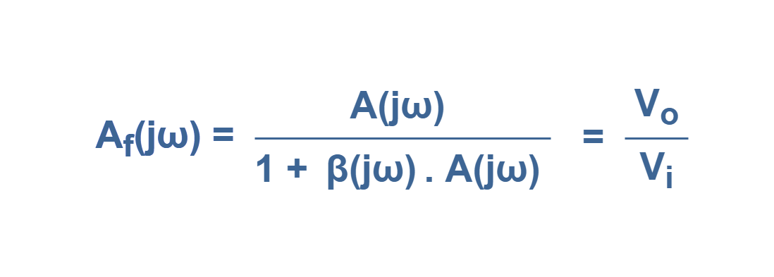
where the product of A(jω)β(jω) is called the loop gain.
Effect Of Negative Feedback On Gain And Bandwidth
While positive feedback drives an amplifier circuit toward a point of instability (oscillations), negative feedback drives it toward a point of stability. An amplifier circuit equipped with some amount of negative feedback is not only more stable, but it distorts the input waveform less and is generally capable of amplifying a wider range of frequencies. The trade-off for these advantages is decreased gain.
So, The net result of negative feedback is stability in the amplifier characteristics. Negative feedback may also prevent a transistor/ op-amp amplifier circuit from thermal runaway. Negative feedback also has the advantage of making amplifier total gain more dependent on resistor values and less dependent on the characteristics of semiconductor elements.
In Equation 1, the overall gain with negative feedback is shown. In the condition that the loop gain is large enough, the expression of the formula becomes simplified as shown in Equation 2:
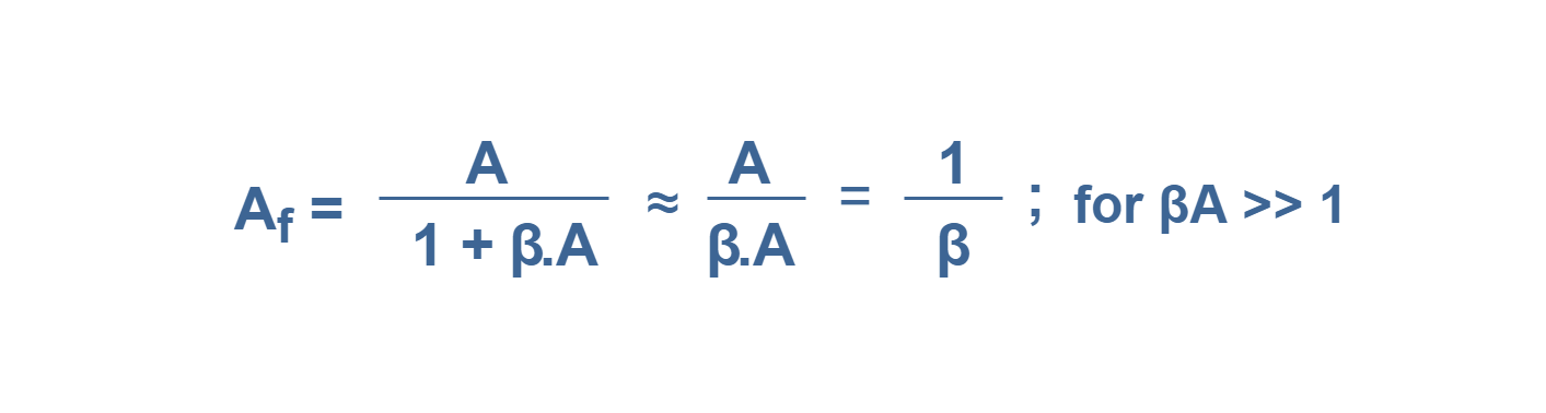
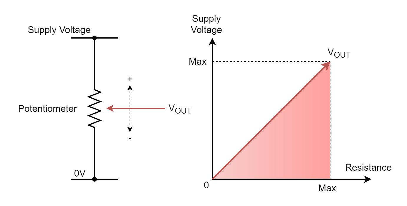
As long as βA >> 1, the overall gain is approximately 1/β. the gain or transfer function of the feedback amplifier essentially becomes a function of the feedback network only. This part of the system can be a very simple resistive circuit, as a voltage divider.
In some of the active amplifier circuits, the individual parameters may vary widely depending on frequency and temperature. It means the value of open-loop gain ‘A’ is not constant in time. But, in a purely resistive feedback circuit, the feedback network gain ‘β’ can be constant. Thus, the overall gain with feedback is not dependent on temperature or frequency and changes in internal components cause little effect on the output. This makes an amplifier stable and easy to design.
Similarly, the frequency distortion because of varying amplifier gain with frequency is considerably reduced in a negative feedback amplifier circuit. It means feedback causes a Reduction in Frequency Distortion.
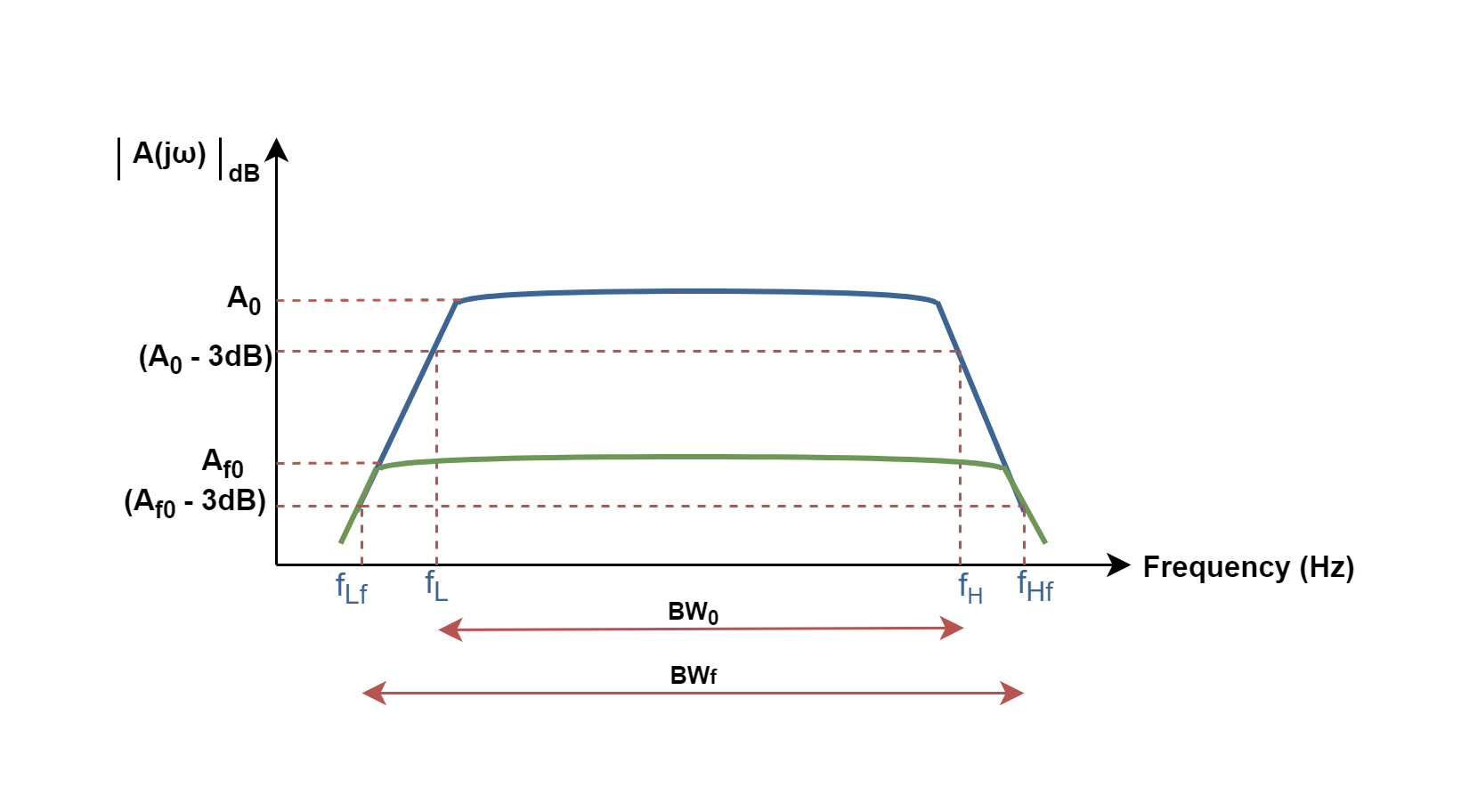
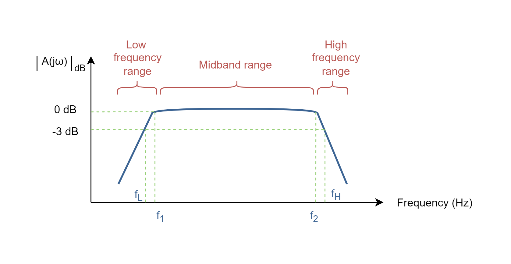
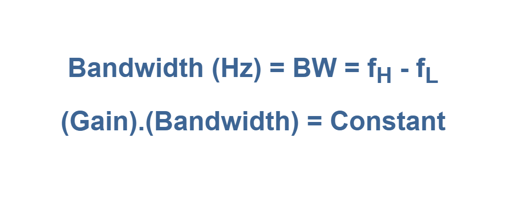
As a matter of fact, the gain-bandwidth product of the basic amplifier is the same value as the feedback amplifier. It is also interesting to note that although the use of feedback has the result of lowering the gain, it provides an increase in bandwidth particularly. It means the range of frequencies the amplifier can operate is extended in the feedback system. Figure 2 shows that the amplifier with negative feedback has more bandwidth (BWf) than the amplifier without feedback (BW0), while its gain has decreased from A0 to Af0.
Reduction Of Nonlinear Distortion
Distortion in an output signal is caused by a change in the basic amplifier gain or the slope of its transfer function. The change in gain can be a function of the nonlinear properties of semiconductor components used in the basic amplifier.
According to Figure 1 configurations, ‘A’ (in simple notation without the argument), is the gain of the amplifier stage alone and without feedback. With feedback β, the overall gain of the circuit is reduced by a factor (1 + βA). Negative feedback has a “damping” effect on an amplifier: if the output signal becomes increased in magnitude, the feedback signal introduces a reversed influence into the input of the amplifier, thus decreasing the change in the output signal. For this reason, in a feedback system, the output changes with fewer variations for a given input signal than without feedback. The term (1 + βA) is also called the desensitivity factor.
Naturally, any real amplifier transfer function has changed in gain but, whereas the open-loop gain ‘A’ changes by a large factor, the closed-loop gain {A/ (1 + βA)} changes by only some percent. A smaller change in overall gain means less distortion in the output signal of the negative feedback amplifier and possibly having near-ideal linearity.
Let us consider a numerical example. If the value of ‘A’ equals 100,000 and the value of ‘β’ equals 0.01, then the overall gain of the feedback system will be:
Af = A/ (1 + A. β) = 100,000 / [1 + (100,000)(0.01)] = 99.90
Now, if the value of A changes to 150,000, then we will have:
Af = A/ (1 + A. β) = 150,000 / [1 + (150,000)(0.01)] = 99.93
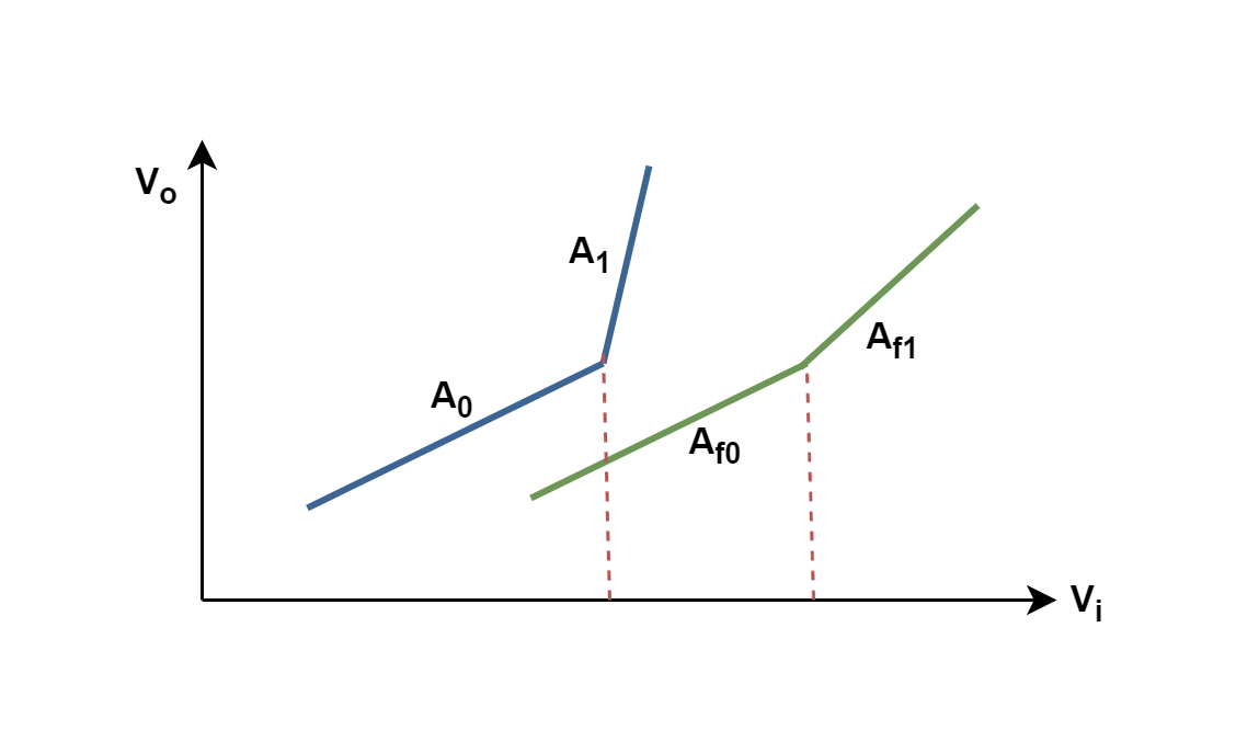
Figure 3 roughly (not in scale) shows the comparison between the transfer functions of an open-loop system (blue curve) and a closed-loop system (green curve). While the gain of the open-loop system has a big change from A0 to A1, the gain of the feedback system changes from Af0 to Af1 more smoothly.
Reduction Of Noise Sensitivity
In any electronic system, unwanted random and irrelevant signals may be present in addition to the desired signal. These random signals are usually called noise. Electronic noise can be generated within an amplifier or may enter the amplifier along with the input signal. The noise produced within an amplifier can be reduced by the factor (1 + βA) for considerable improvement. On the other hand, it may increase the signal-to-noise ratio (SNR) at the output of the system.
More precisely, feedback can help reduce the effect of noise generated in an amplifier (such as power-supply hum), but it cannot reduce the effect when the noise is part of the input signal. A large signal-to-noise ratio obviously allows the signal to be detected without any loss of information. This is a desirable characteristic.
The output signal-to-noise ratio is defined in Equation 3, where So is the power of desired output signal and No is the power of the noise (unwanted) signal at the output.

Feedback Connection Types
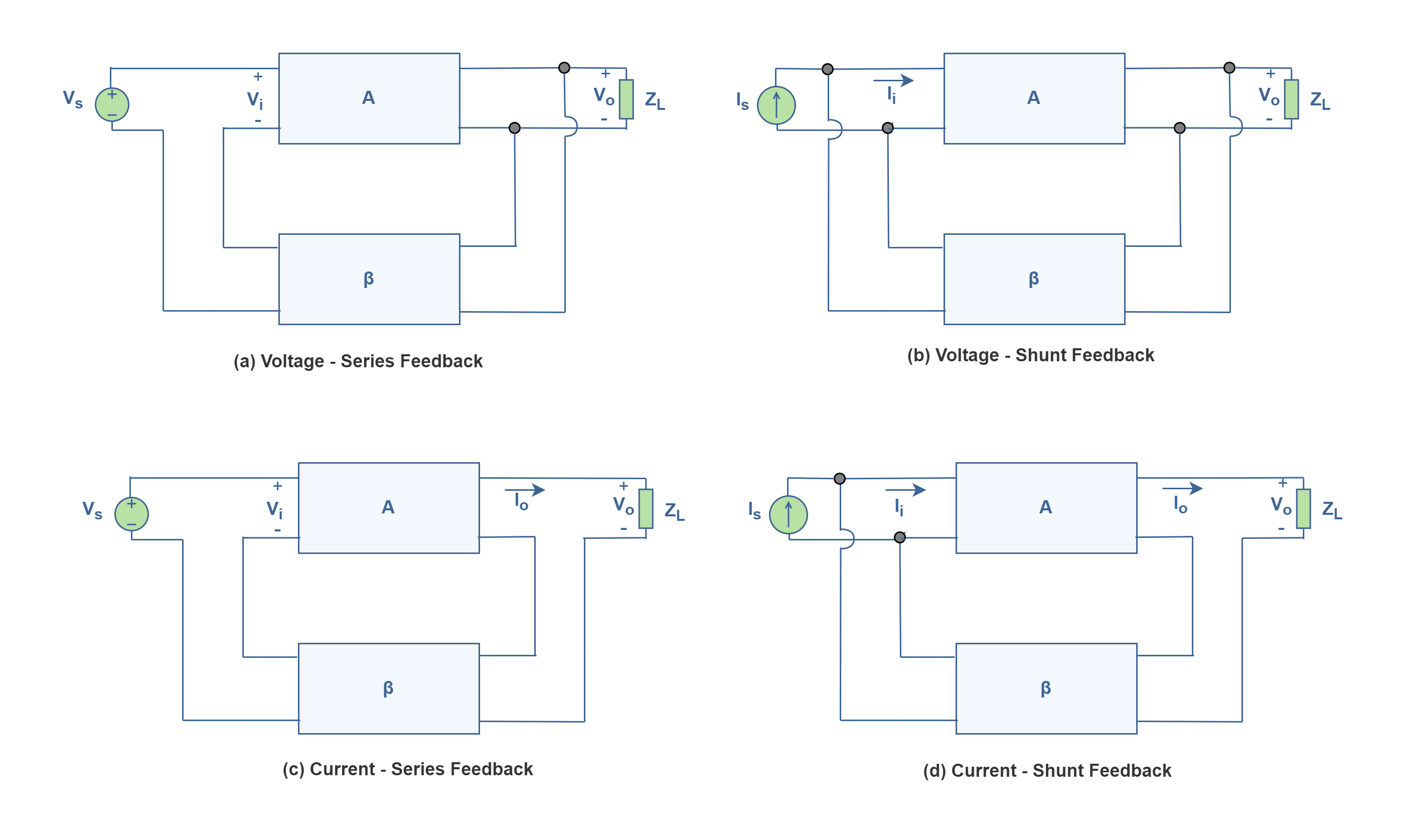
There are four basic ways of connecting the feedback signal. These designations correspond to the input- and output-port connections, respectively, between the feedback network and the basic amplifier. Both voltage and current can be fed back to the input either in series or parallel. Specifically, there can be:
- Voltage-series feedback (Figure 4 a).
- Voltage-shunt feedback (Figure 4 b).
- Current-series feedback (Figure 4 c).
- Current-shunt feedback (Figure 4 d).
The first term refers to the connection at the output, and the second term refers to the connection at the amplifier input. In the list above, voltage refers to connecting the output voltage as input to the feedback network while current refers to tapping off some output current through the feedback network. Also series refers to connecting the feedback signal in series with the input signal voltage while shunt refers to connecting the feedback signal in shunt (parallel) with an input current source. The type of connection determines which parameter (voltage or current) is sampled at the output and which parameter is amplified. Impedance levels decrease when networks are connected in parallel and increase when they are series-connected.
The connections also determine the feedback amplifier characteristics—in particular, the input and output resistances. The resistance parameters become an important circuit property, when, for example, we consider voltage amplifiers versus current amplifiers.
The topology of the feedback system can change the characteristics of the whole network in comparison to the basic amplifier network alone. Feedback offers the designer the choice of different specifications without changing the parameters of the basic amplifier stage.
Input And Output Impedances With Feedback
A summary of input and output impedances with feedback configurations in Figure 4 is provided in Table 1. The source and output signals in the table are referred to as the feedback stage (circuit) while input and output impedances are referred to as the overall network.
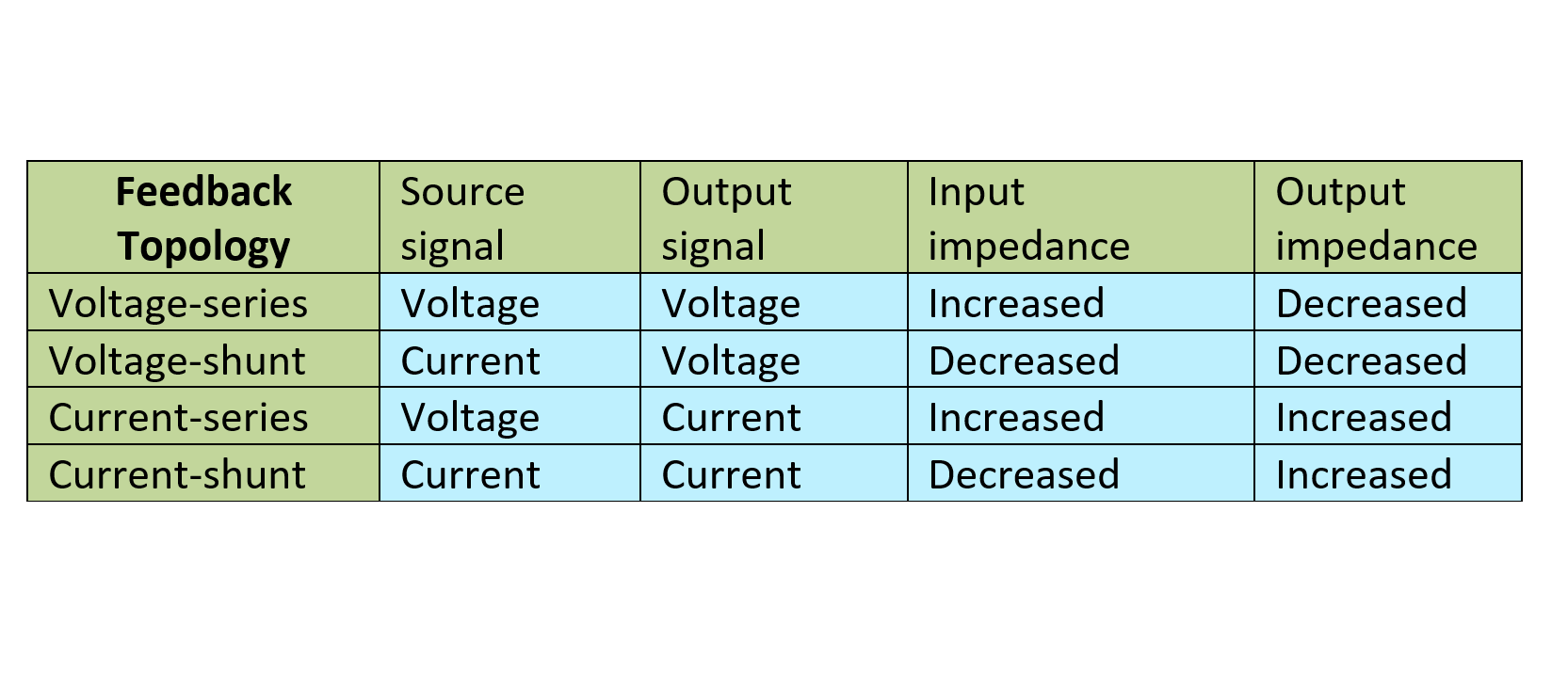
It is clear that series feedback connections tend to increase the input resistance, whereas shunt feedback connections tend to decrease the input resistance. Voltage feedback tends to decrease the output impedance, whereas current feedback tends to increase the output impedance. The factor by which the impedance changes is (1 + βA).
A Practical Example Of Using Op-amps (Operational Amplifiers) In Feedback Systems
The name operational amplifier, or op-amp, came into being to describe the fact that these amplifiers were used to create circuits in analog computers, performing some operations like multiplication, differentiation, and so on. Ideal operational amplifiers are typically modeled with very high (ideally infinite) input impedance and very low (ideally zero) output impedance and specifically with very high (ideally infinite) open-loop voltage gain. The trick to making op-amps useful and practical devices involves applying negative feedback. When voltage is “fed” back from the output terminal to the inverting terminal, the gain of an op-amp can be controlled and reduced to reasonable levels. This feedback information specifically tells the op-amp to readjust its output voltage to a value determined by the resistance of the feedback resistor.
The basic circuit connection using an op-amp is shown in Figure 5.
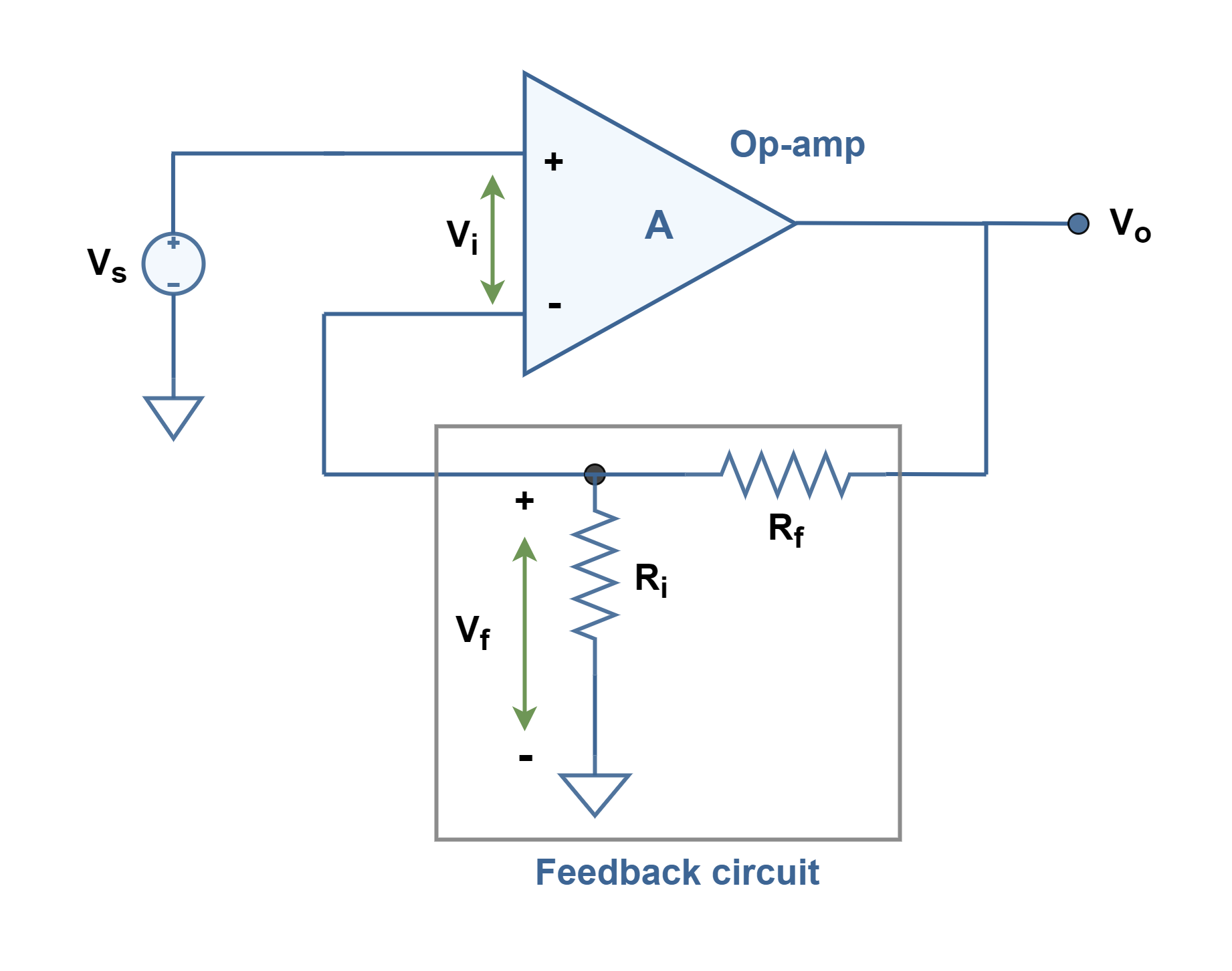
To achieve loop-gain of larger than 1, we should set β less than 1. The type of configuration of this circuit is a voltage-series feedback connection. In the set of Equations 4, the relationship between parameters are expressed. Vo is the op amp’s output voltage as a function of its input voltages V+(noninverting) and V–(inverting) and of its open-loop voltage gain ‘A’ (Equations 4-a). The high gain of the op-amp ‘A’ without feedback, is reduced by the feedback factor of β which is calculated for a simple resistive voltage divider (Equations 4-b). Finally, Equation 4-c shows the overall voltage gain with feedback based on values of 2 resistances.
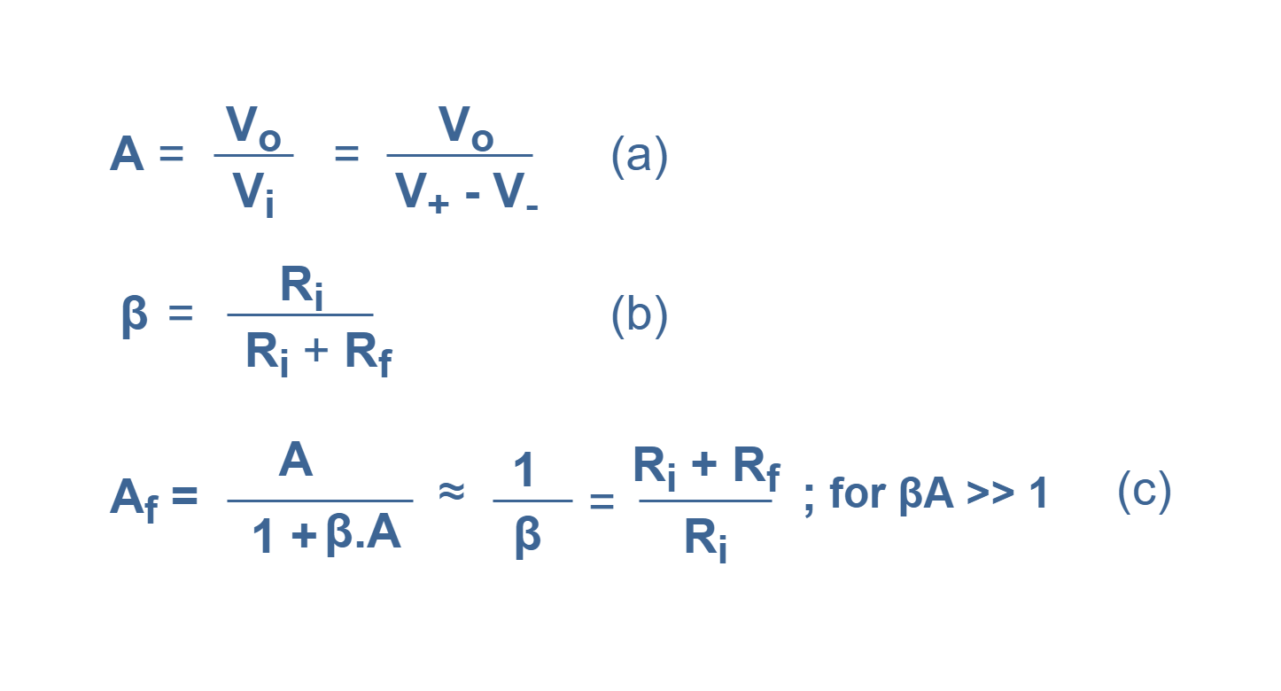
Let us consider a numerical analysis. If we have A = 100,000 as the open-loop gain, and Rf = 2 kΩ and also Ri = 200 Ω, then we can find the parameters as:
β = feedback factor= 200 / (2000 + 200) = 0.09
βA = loop-gain = (0.09)(100,000) = 9000
Af = close-loop gain = 100,000 / (1 + 9000) = 11.10
Note that since βA >> 1, we can also calculate with suitable approximation:
Af ≈ 1/ β = 11.11
It is obvious that two simple resistors control the gain of this circuit. The op-amp circuits are sometimes easier to analyze and calculate than transistor amplification circuits.
Summary
- The feedback process takes a portion of the output signal and returns it to the input to become part of the input excitation.
- Negative feedback is implemented simply by coupling the output back in such a way as to cancel some of the input signals.
- Negative feedback has some advantages as follows:
- Better stabilized voltage gain (self-stabilizing); Variations in the circuit transfer function (gain) as a result of changes in transistor parameters are reduced by feedback. It means circuit performance is insensitive to manufacturing and environmental changes. This is one of the most attractive features of negative feedback.
- Improved frequency response (bandwidth improvement); The bandwidth of a circuit that incorporates negative feedback is larger than that of the basic amplifier.
- Higher input impedance and lower output impedance (control of impedance levels); The input and output impedances can be increased or decreased with the proper type of negative feedback circuit.
- Reduced noise (Noise sensitivity reduction); Negative feedback may increase the output signal-to-noise ratio if noise is generated within the feedback loop.
- More linear operation and lower distortions (Reduction of nonlinear distortion); Since transistors have nonlinear characteristics, distortion may appear in the output signals, especially at large signal levels. Negative feedback reduces this distortion.
- Negative feedback also has some disadvantages:
- Circuit gain. The overall amplifier gain, with negative feedback, is reduced compared to the basic amplifier used in the circuit.
- Instability condition. There is a possibility that the feedback circuit may oscillate especially at high frequencies.