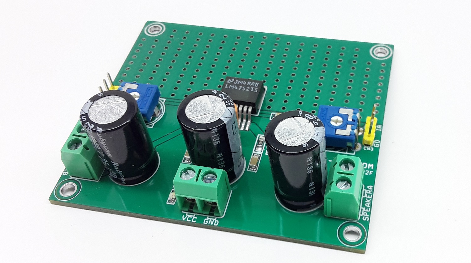
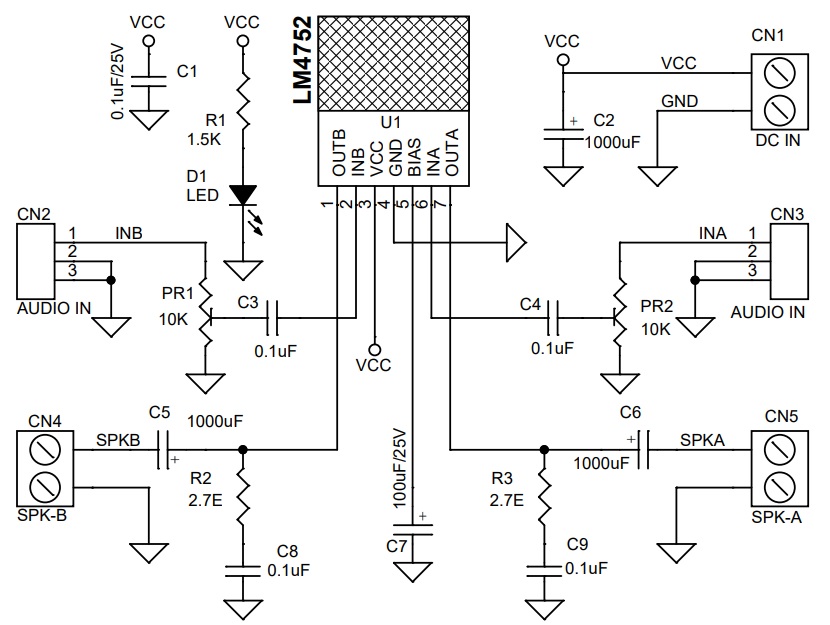
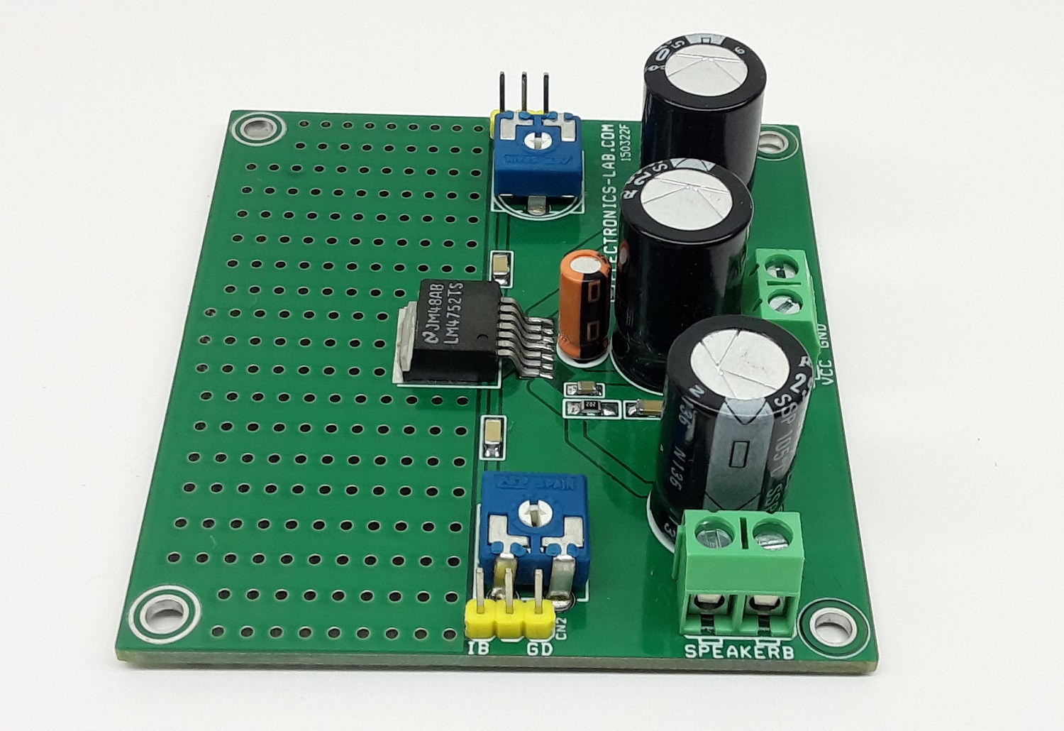
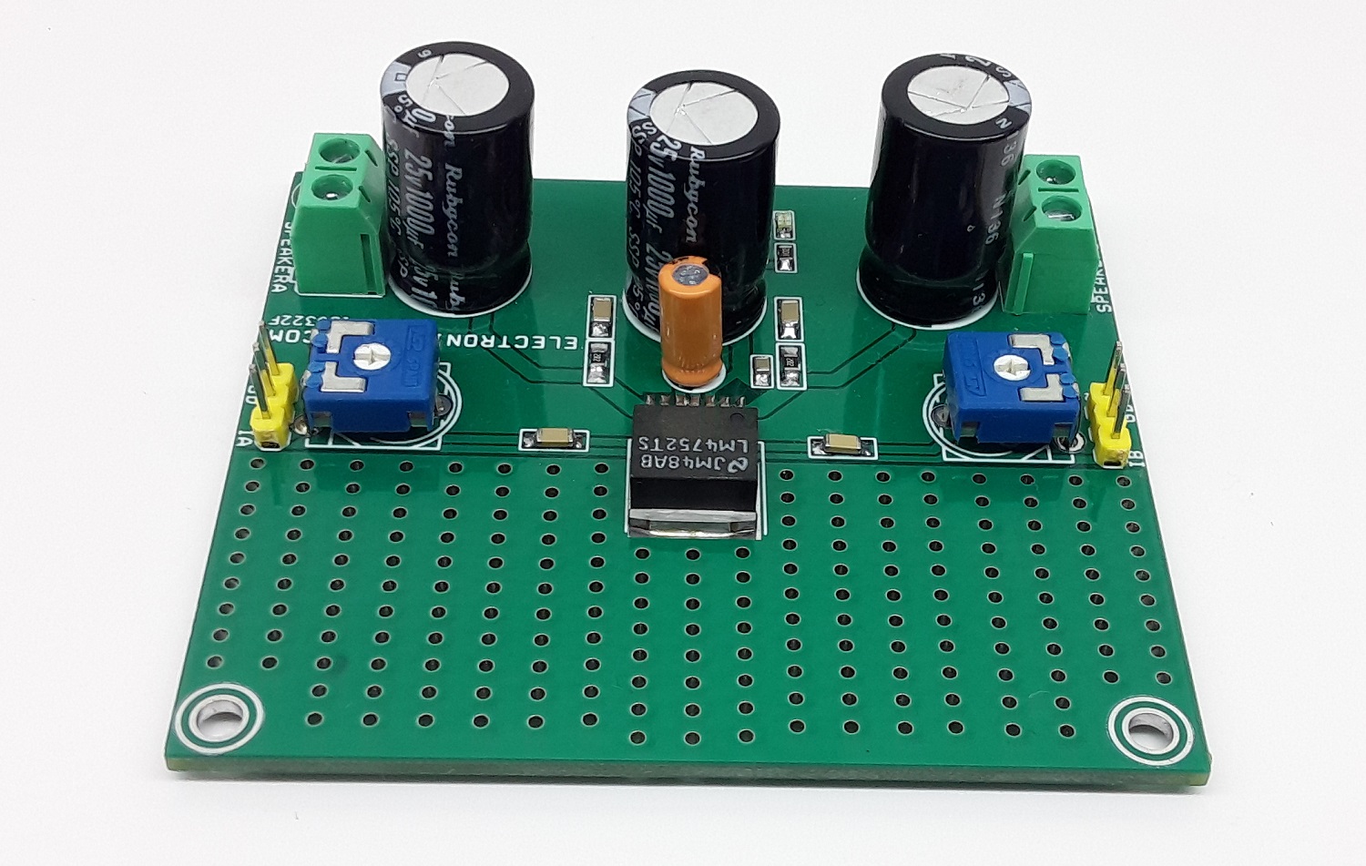
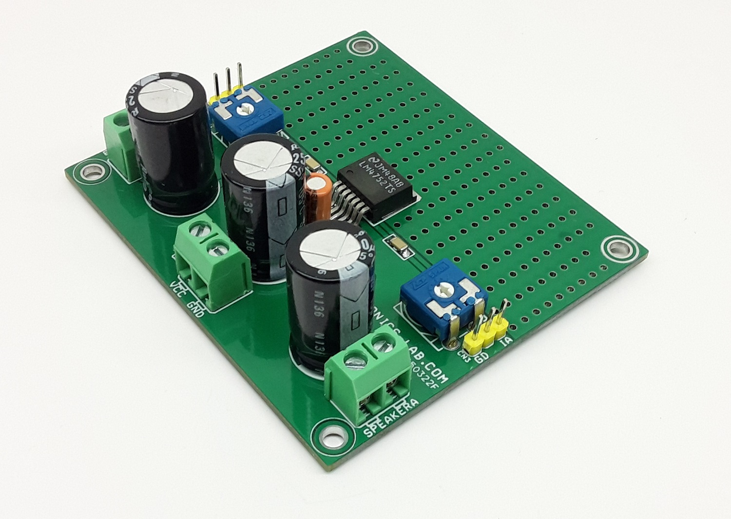
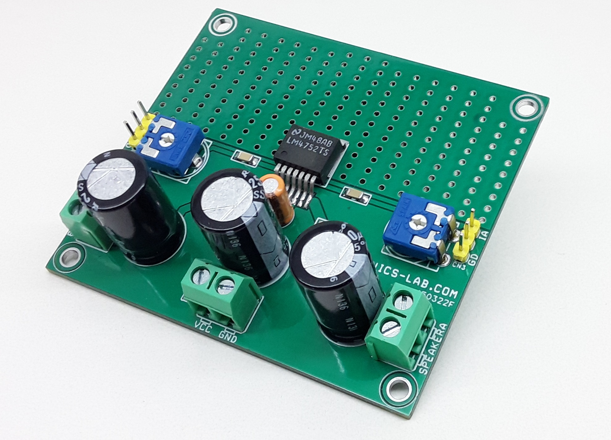
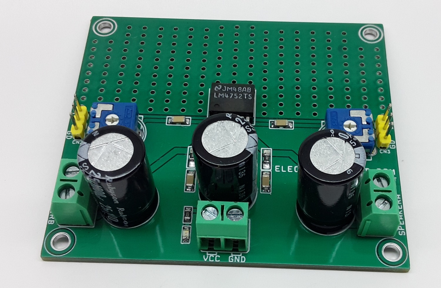
The Stereo Audio Amplifier project shown here is capable of delivering 2.5W per channel of continuous average output power to 4Ω loads using a single 12V supply at 10% THD+N. The project is built using the LM4752 chip. This chip is specifically designed for single supply operations and low external components count. The gain and bias resistors are integrated on-chip, resulting in a 2.5W stereo amplifier in a compact 7-pin TO263 SMD package. High output power levels at 12V supplies and low external component count offer high value for compact stereo and TV applications. Sufficient power dissipation is provided on PCB so no external heatsink is required for IC.
Features
Supply 12V-16V DC
PO 2.5W Stereo at 10% THD+N @ 1 kHz into 4Ω
Drives 4Ω and 8Ω Loads
Internal Gain Resistors (AV = 34 dB)
Minimum External Component
Single Supply Operation
Internal Current Limiting
Internal Thermal Protection
On-Board Power LED
On-Board Trimmer Potentiometer for Volume Control
Screw Terminal for Power Supply
Screw Terminal for Speaker Connections
3 Pin Male Header for Audio Signal Input
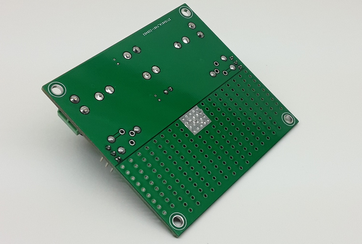
On-Board Thermal Area for Power Dissipation
4 x 3 mm Mounting Holes
PCB Dimensions 75.72 x 89.99mm
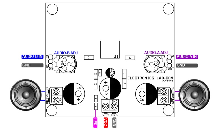
Connections
CN1: Pin 1 VCC, Pin 2 GND
CN2: Audio Signal Input Channel B
CN3: Audio Signal Input Channel A
CN4: Speaker Channel B
CN5: Speaker Channel A
PR1: Trimmer Potentiometer for Channel B Audio Volume Control
PR2: Trimmer Potentiometer for Channel A Audio Volume Control
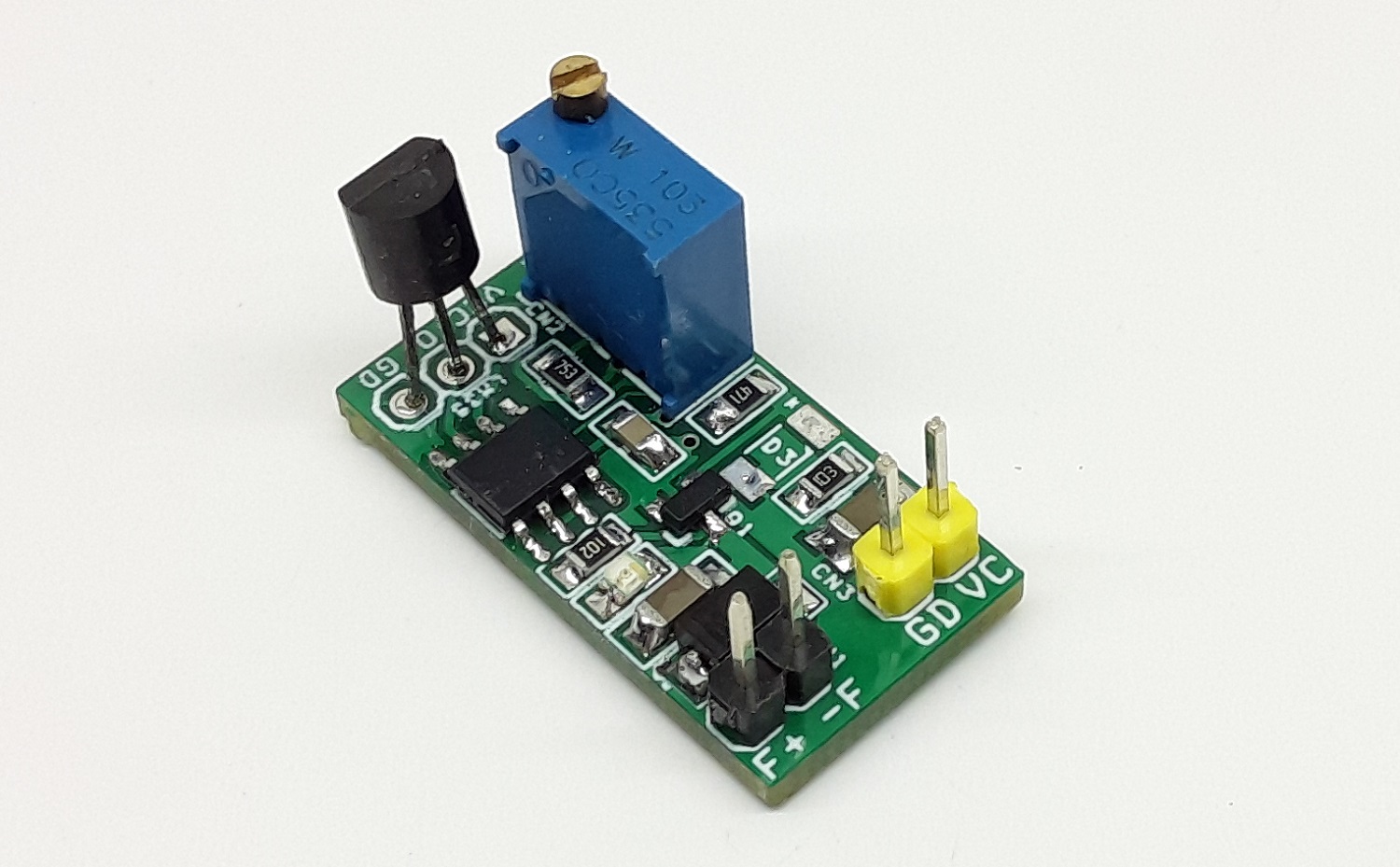
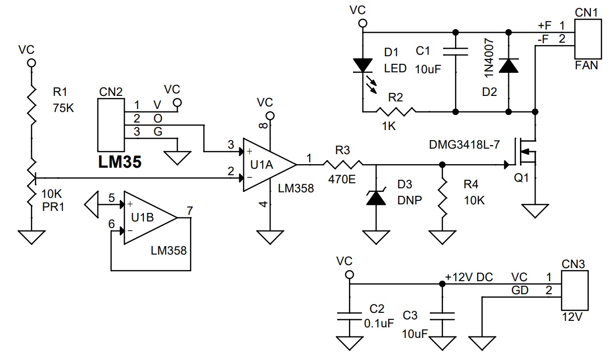
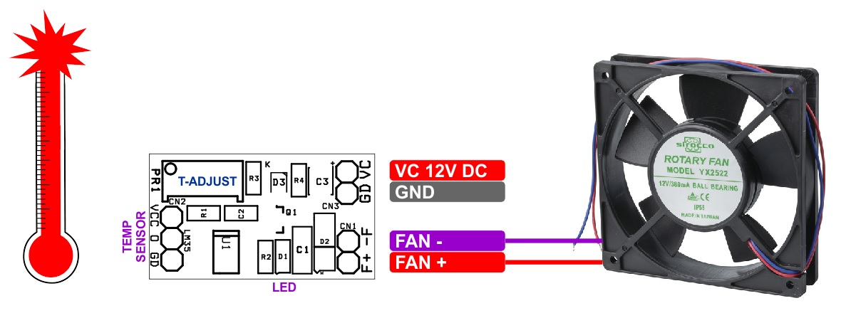
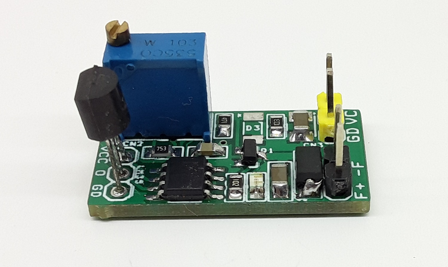
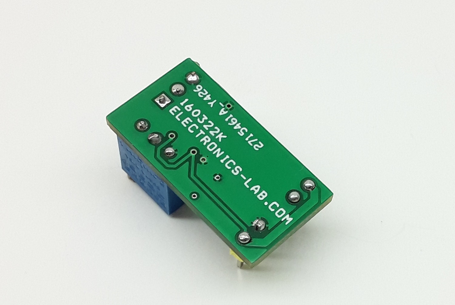
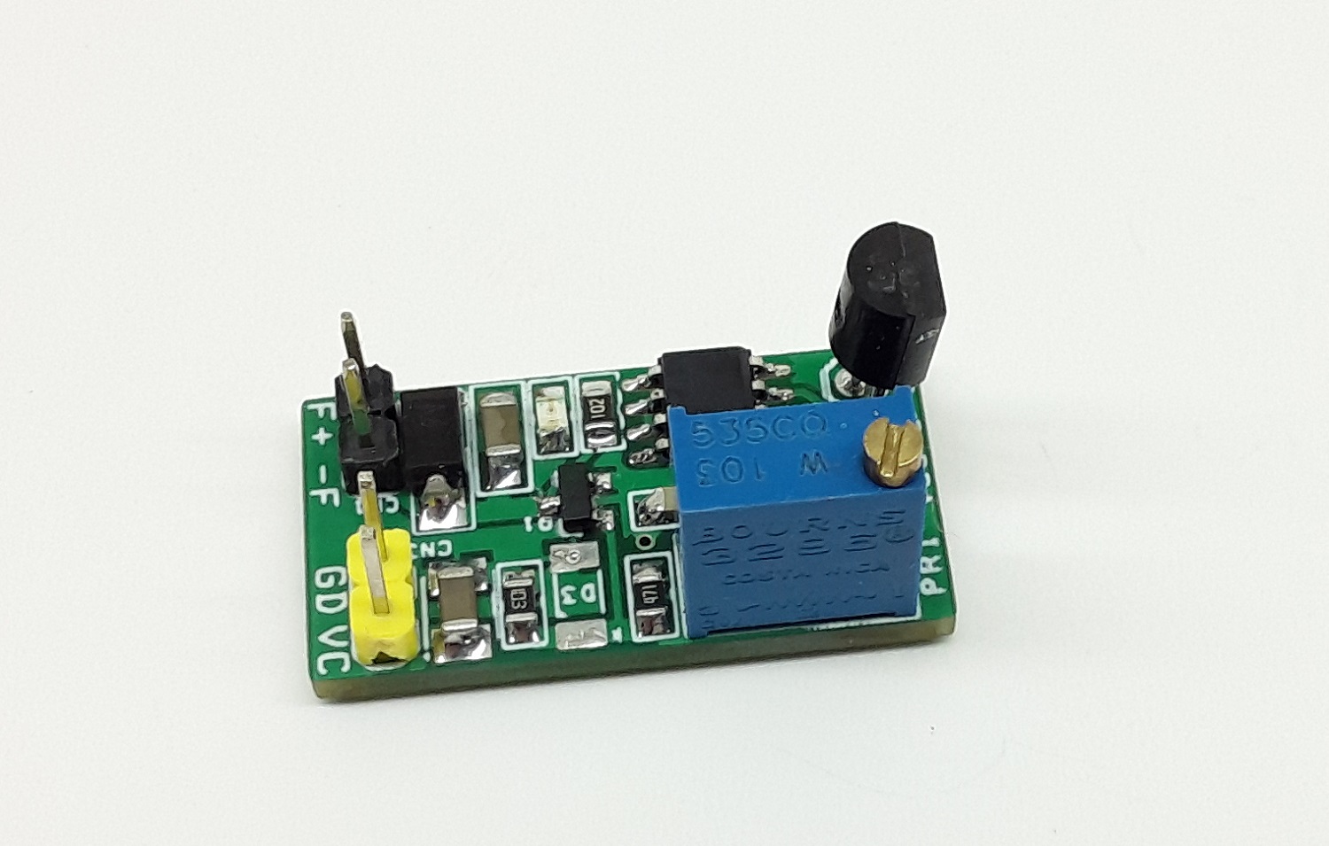
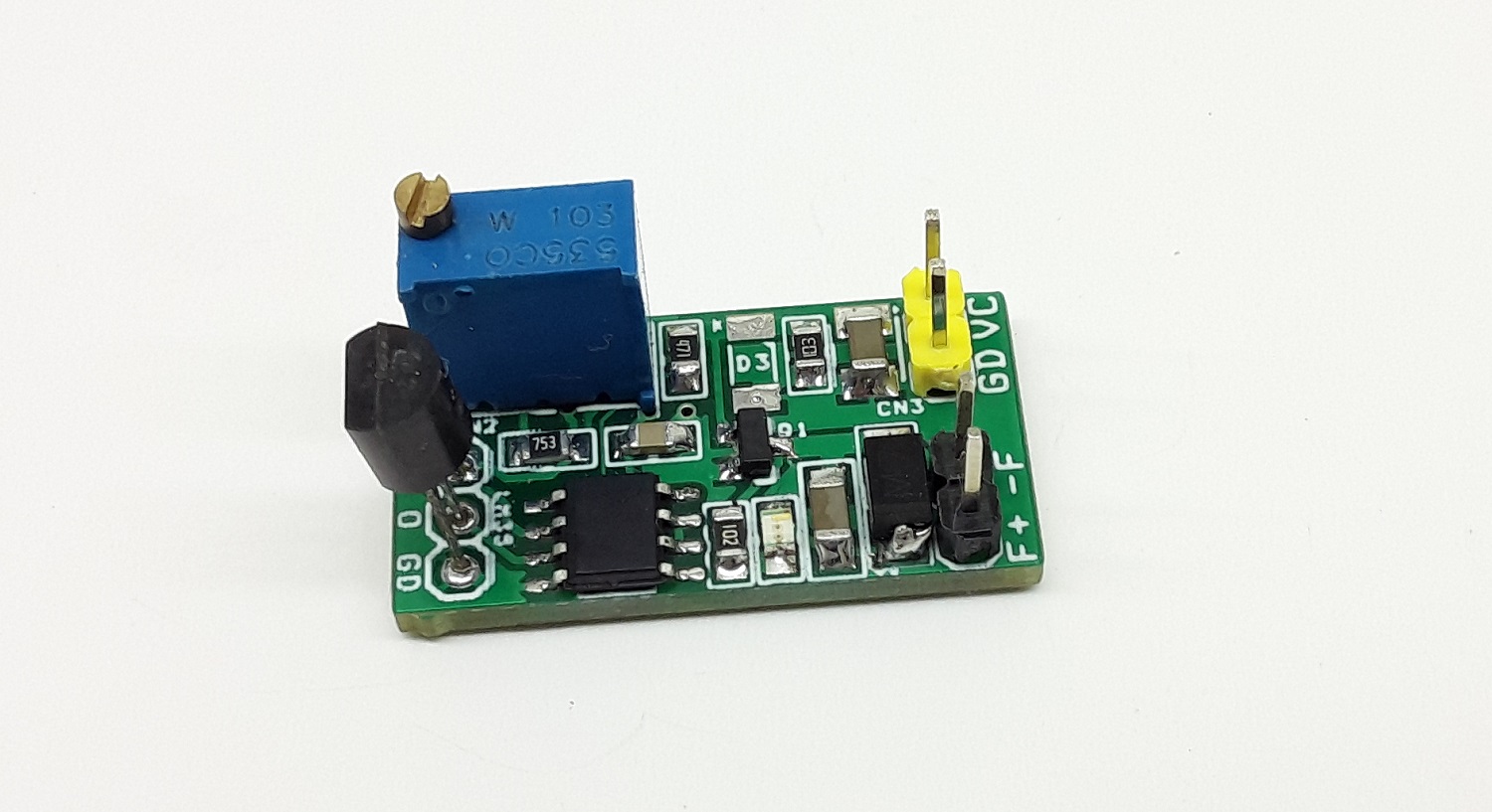
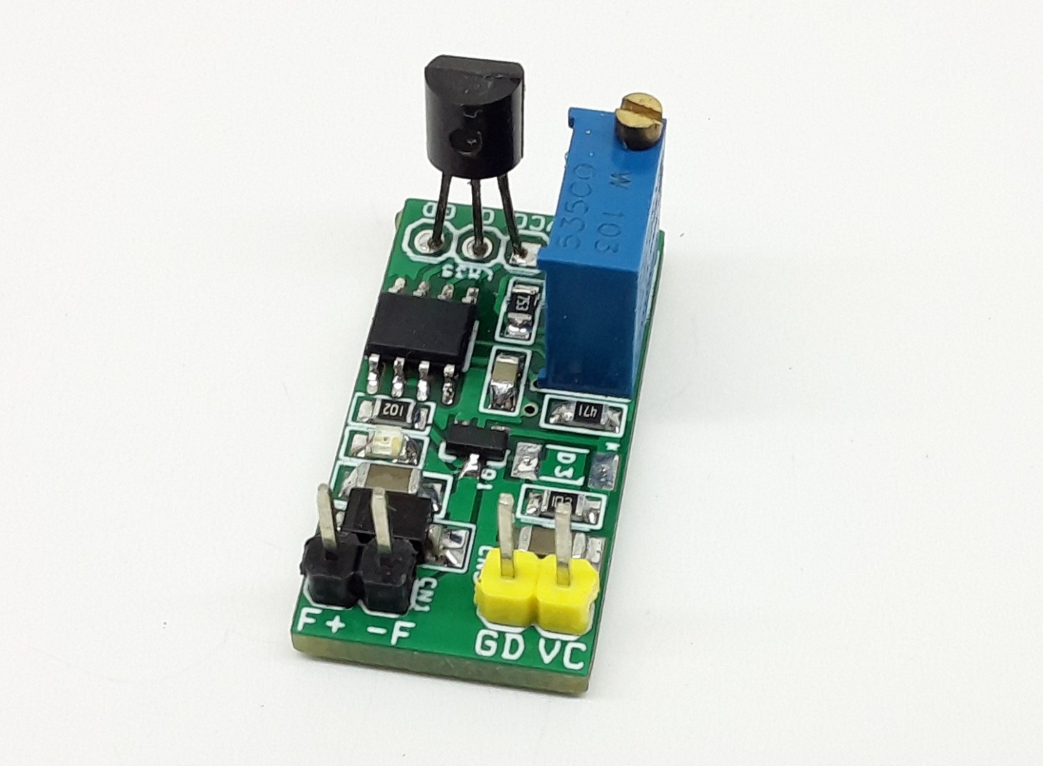
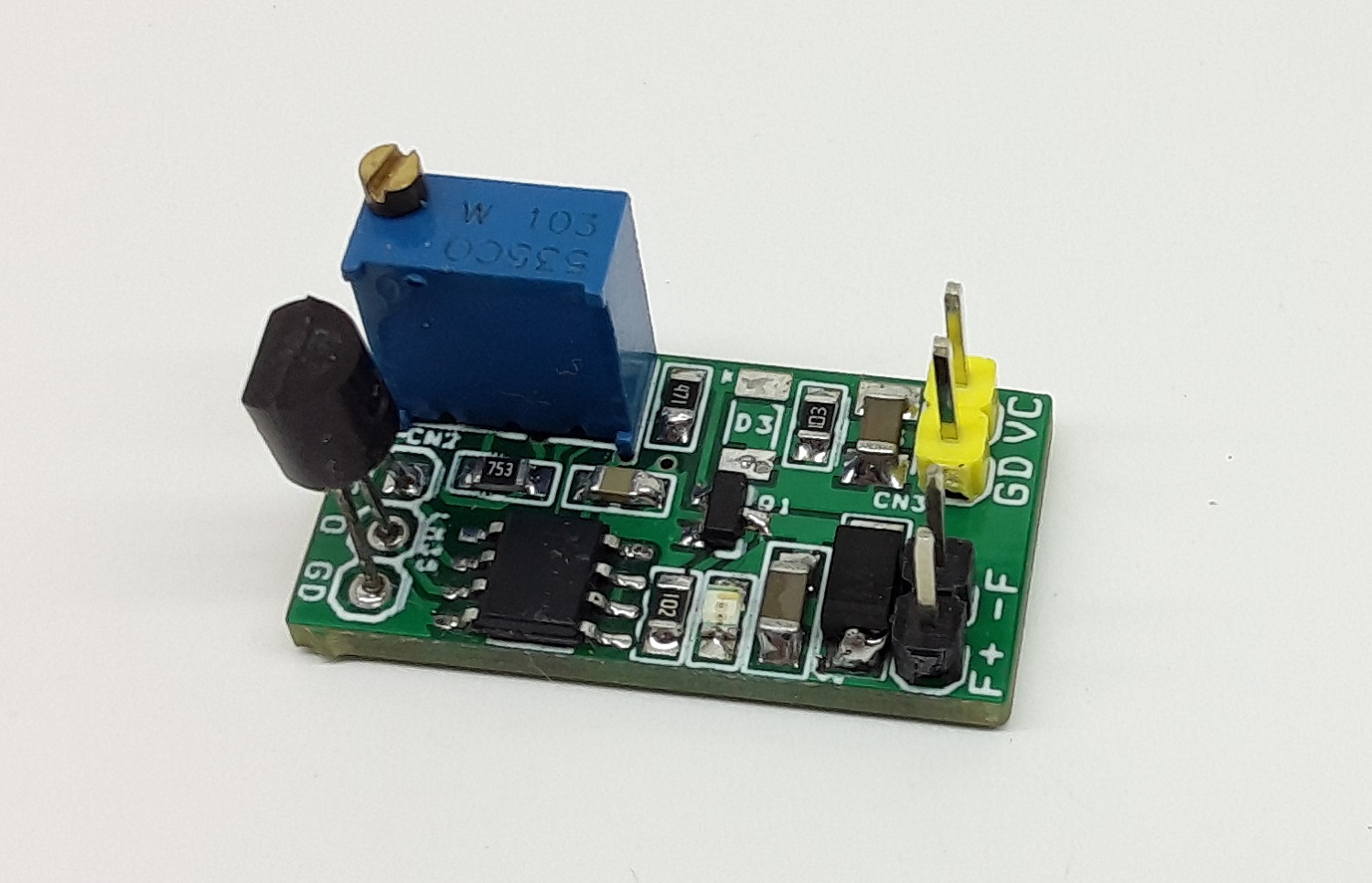
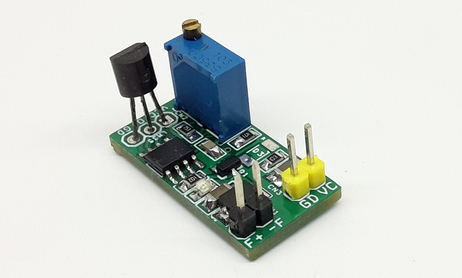
The project presented here is a low-cost solution for heat management of the heatsink and various equipment that requires automatic control of a cooling Fan. The project is built using a very cheap LM358 OPAMP. LM358 is used as a comparator, and a trimmer PR1 is provided to set the temperature threshold (Fan ON trigger point). LM35 is used as a temperature sensor, it outputs an analog output voltage that is proportional to temperature. Capacitors C2 and C3 are bypass capacitors, D2 is a clamp diode to protect the Q1 MOSFET from reverse electromagnetic noise coming from the fan. Capacitor C1 helps in noise control while Fan is ON/OFF. LED D1 indicates Fan ON/OFF operations. Q1 MOSFET DMG3418L-7 can handle current up to 4A. LM35 can be mounted directly on the heatsink using silicon glue or with help of a mechanical fixture for proper temperature sense. The sensor senses the temperature, the output of the sensor rises as the temperature rise, and the comparator compares the sensor output with the threshold voltage of the PR1 trimmer potentiometer. When the sensor output is above the set point, LM358 provides a high output which triggers the MOSFET, and finally, the fan goes ON. The fan runs until the temperature drops less than the set point.
Features
Supply 12V DC (Range 5V to 12V DC)
Fan Load Up to 1Amp Continues (Maximum Load 4Amps)
Temperature Threshold Range Adjustable 10 to 100 Degree Centigrade using Multiturn Trimmer Potentiometer.
Simple and Low-Cost Temperature Management Solution for Heatsink or Equipment
On-Board Trimmer Potentiometer to Adjust the Temperature Threshold
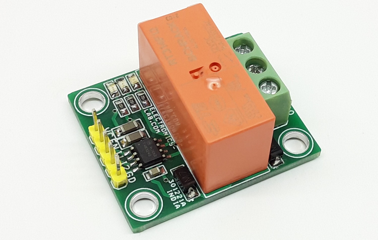
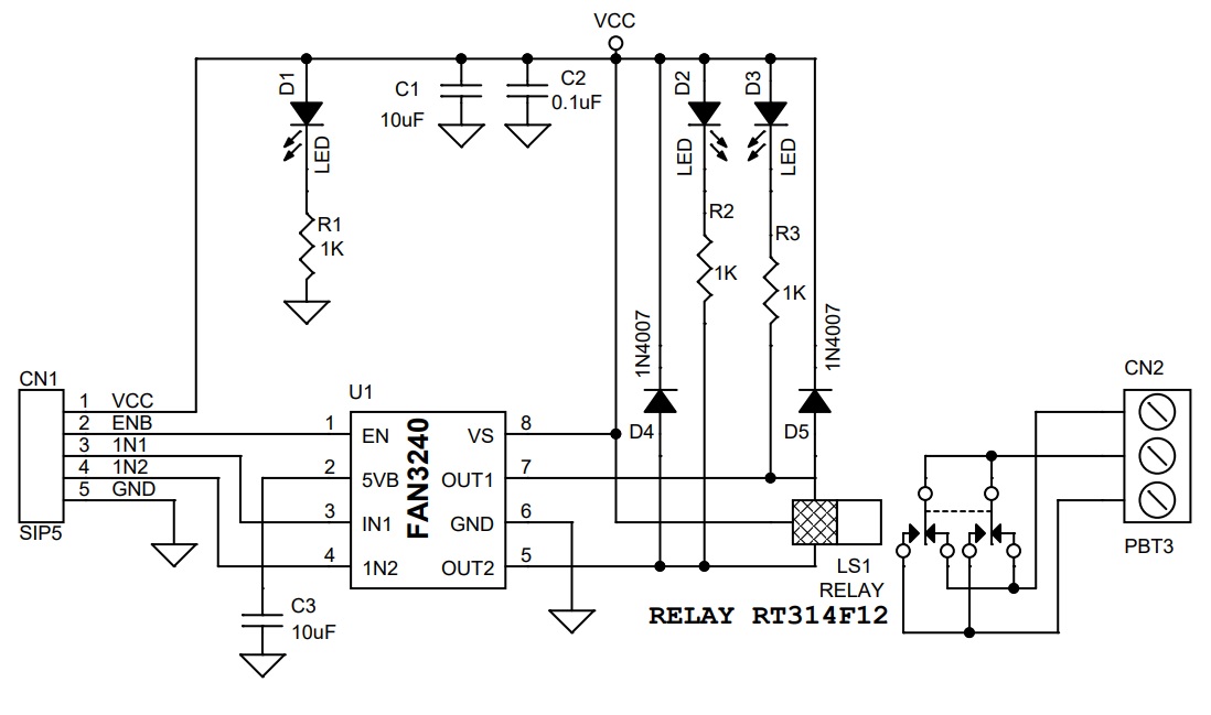
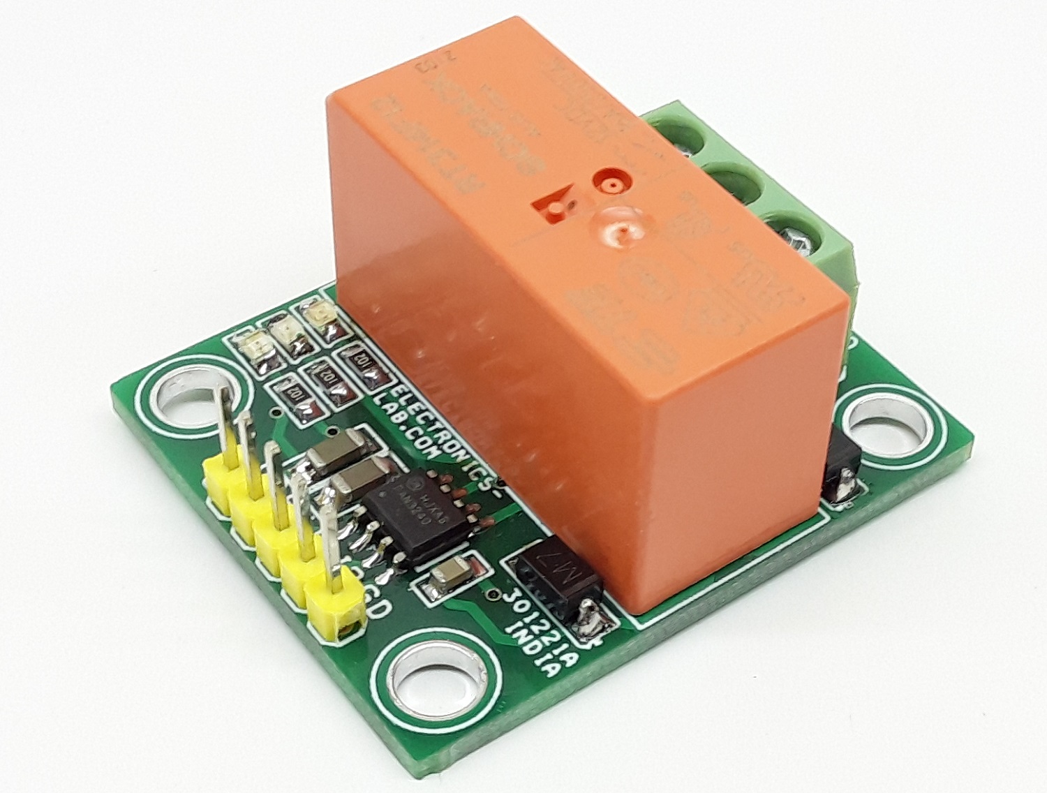
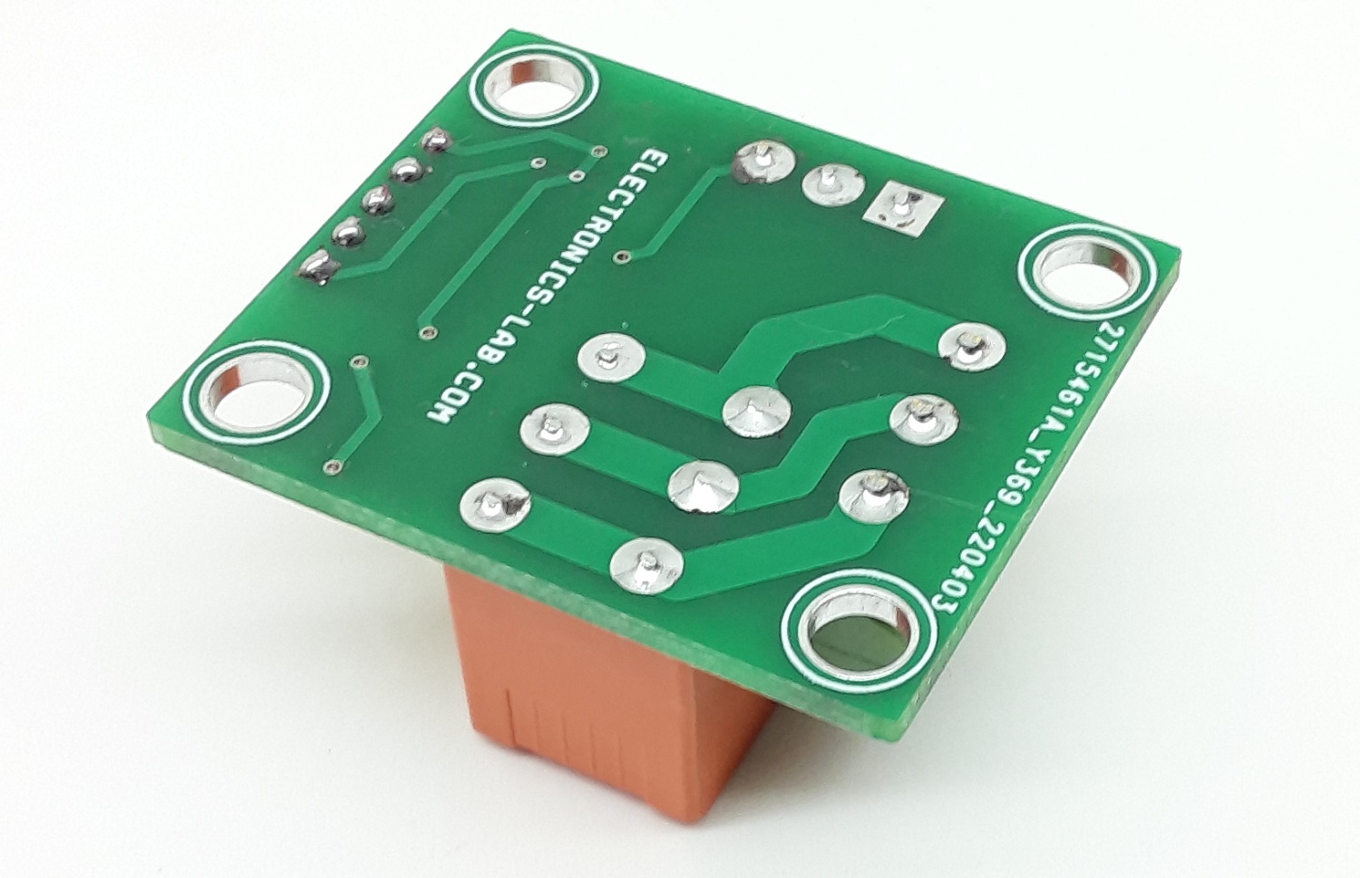
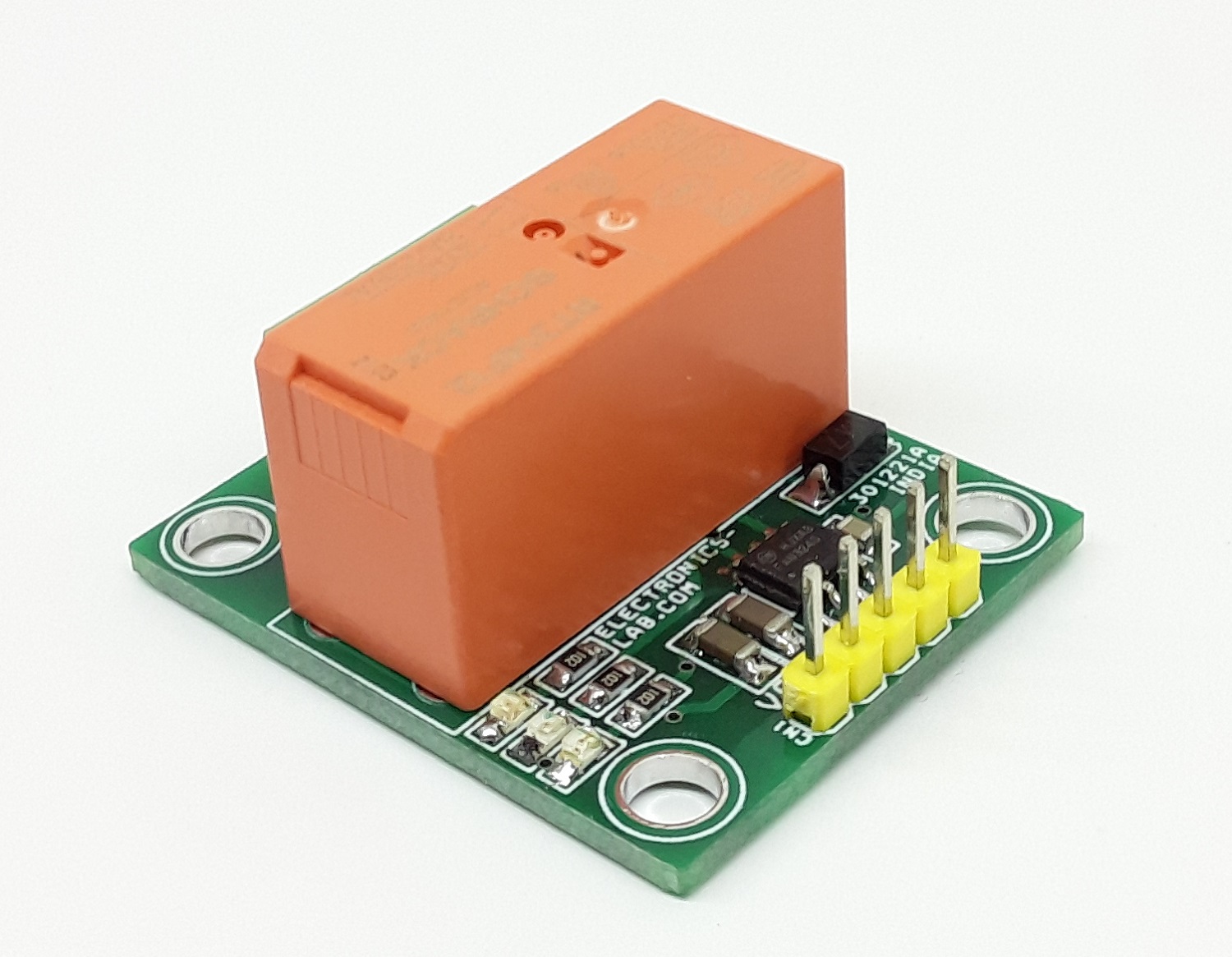
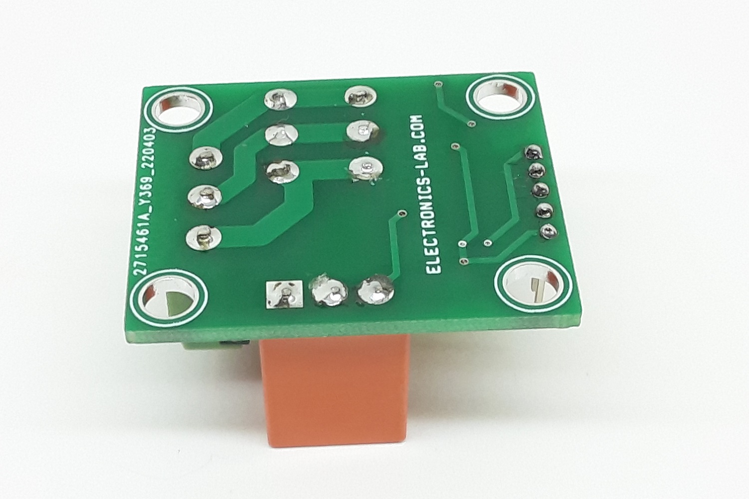
This Smart Dual Coil latching Relay board can control the ON/OFF power of a device by applying a short voltage pulse to input 1 and input 2. This project is useful in low power applications since the coil is not powered all the time and only requires a short voltage pulse. The relay coil remains in that position even if the power is disconnected. The project is built using FAN3240 chips from ONSEMI. This chip includes dual high current relay drivers designed to drive dual-coil polarized latching relays that connect and disconnect power in smart electronic meters and solar inverter applications. The IC includes auto thermal shutdown and a filter/timer block is there to prevent inadvertent switching from noisy input signals by providing input-pulse qualification (tQUAL) and maximum output pulse width limit (tMAX). Polarized, bi-stable, latching relays are utilized in many kinds of electronics equipment and diverse applications. These relays usually employ two coils, one to move the relay contacts(s) from open to close position and another coil to move the contacts(s) from close to open position. To facilitate mechanical movement, the relay coils need to be energized for a specific time interval. Once the contact(s) have changed position, the voltage should be removed from the winding of the relay. As shown in the schematic below, a dual-coil relay is connected to its supply rail at the center point of the two relay windings. Each winding can be energized by the switches connected to the relay coils out-1 and output-2. Diodes D4 and D5 are used as clamping diodes. Operation is very simple, enable PINs need to be high, apply minimum 15ms trigger voltage to input 1, this will provide 150ms pulse to relay coil -1 and coil moves contact(s) open to close, and when 15ms pulse is applied to input 2, coil-2 energized for 150ms and moves the contact(s) from close to open. Capacitor C3 is a filter capacitor for the internal 5V regulator of the chip.
Note: The project is designed to drive 12V relay, but it can also drive 24V or 48V relay, read the data sheet of chip for components selection.
Note: Pay attention to the TTL logic levels, HIGH voltage should not exceed 5.5V otherwise IC may be damaged. Logic LOW is 0V
Features
Input Supply 12V DC
Maximum Power Consumption Continues 5mA, Maximum 40mA when Relay is triggered for Short Time
Accurate Input Qualification Time 15ms with Output Pulse Width Limit 150ms
Minimum Input Pulse Width 15ms (The minimum input pulse width recognized as a valid input command) T-QUAL
Maximum Output Pulse Width 150ms. Output pulses are terminated after this time interval even if the input pulse is longer or held in a high state continuously, T-Max
Internal Thermal Shutdown Protection
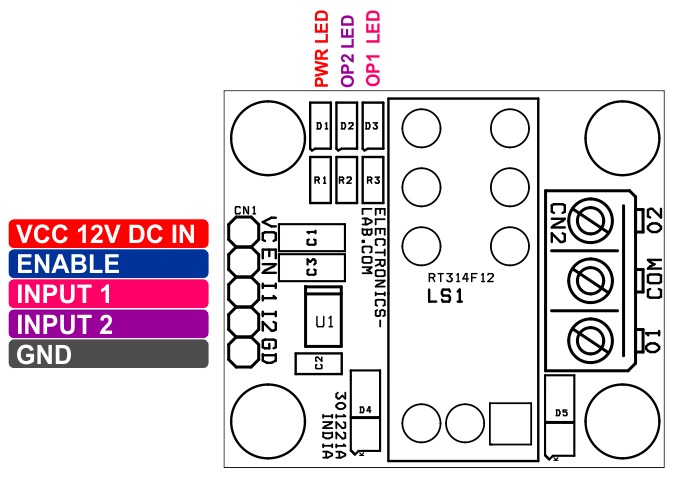
PCB Dimensions 37.15 x 31.27 mm
Connector CN
Pin1: VCC 12V DC @ 40mA
Pin2: Enable/disable pin allows shutdown of both channels (Enable=High Voltage – 5V TTL Level)
Pin3: Input 1 to Set the Output (TTL)
Pin4: input 2 to Reset the Output (TTL)
Pin5: GND
Connector CN2: Relay Output Power ON/OFF Connections
D1 LED: Power LED
D2 LED: Output 2 Indicator
D3 LED: Output 1 Indicator
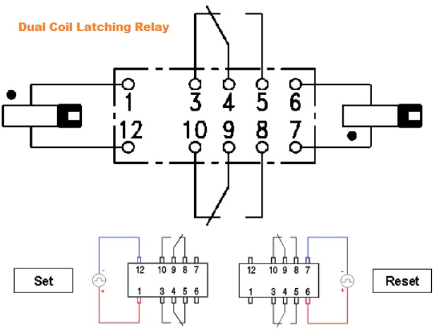
What is Latching Relay/Dual Coil Relay
Latching relays are commonly used in low power consumption or high-temperature applications where applying coil power for a long time cannot be afforded due to power consumption or self-heating of the coil. Instead of a continuous voltage applied to the coil, they are operated with short voltage pulses instead. Latching relays change contact position when a coil voltage is applied and remain in that position even if the voltage is disconnected. (It is common to use the term SET for operating a latching relay). To reset a latching relay another voltage pulse needs to be applied.
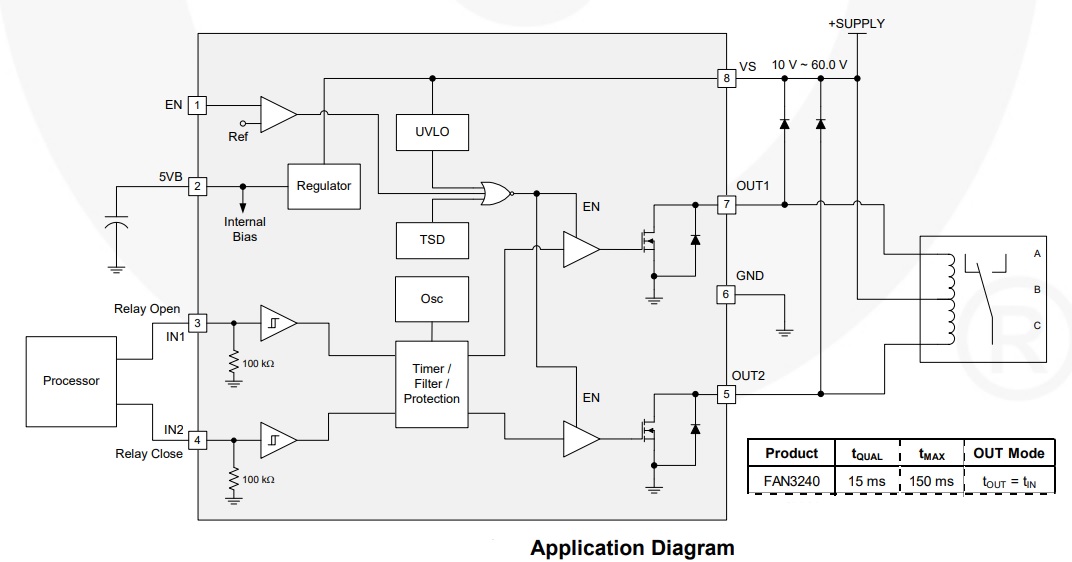
The FAN3240 includes dual high-current relay drivers designed to drive dual-coil polarized latching relays that connect and disconnect power in smart electronic meters and solar inverter applications. The output of the FAN3240 is rated for operation with supply rails from 8 V to 60 V. The filter/timer block prevents inadvertent switching from noisy input signals by providing input-pulse qualification (tQUAL) and maximum output pulse width limit (tMAX). The parameters are factory adjustable and additional configurations are available. XOR input protection is also provided so that both outputs are prevented from being on at the same time. The under-Voltage Lockout (UVLO) function disables the outputs until the supply voltage is within the operating range. The FAN3240 has two separate driver channels with non-inverting logic. One enable/disable pin allows shutdown of both channels, independent of the input signals. Internal thermal shutdown function is provided for thermal protection.
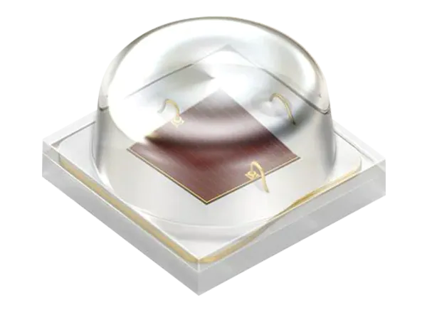
ams OSLON® Optimal LEDs are ideal for horticulture lighting applications with a 1mm² chip inside. The LEDs are housed in a small 3.0mm x 3.00mm footprint package. This allows for very compact clustering. The LEDs have flexible and efficient designs for professional top lighting and inter-lighting designs, and vertical farming solutions.
Features
Small 3.0mm x 3.00mm footprint allows for very compact clustering
Flexible and efficient designs for professional top lighting and inter-lighting designs, and vertical farming solutions
Available in Hyper Red (660nm), Far Red (730nm)
OSLON® Optimal strikes a perfect balance of performance and cost along with proven robustness, high reliability and long lifetime
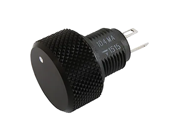
Vishay / Sfernice P16 Compact Panel Potentiometers feature a unique integrated design incorporating the potentiometer and knob in one assembly, with no accessories required. The mounting hardware and terminals are situated on the backside of the panel, reducing the required clearance to a minimum.
The Vishay / Sfernice P16 Compact Panel Potentiometers are fully sealed and have an IP67 ingress rating.
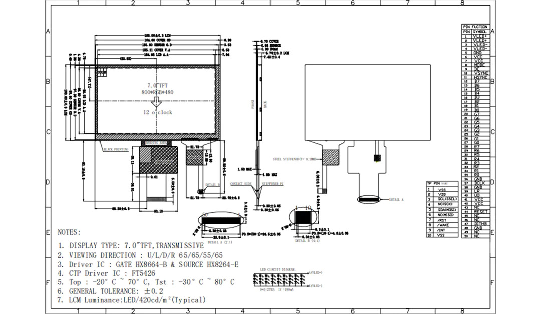
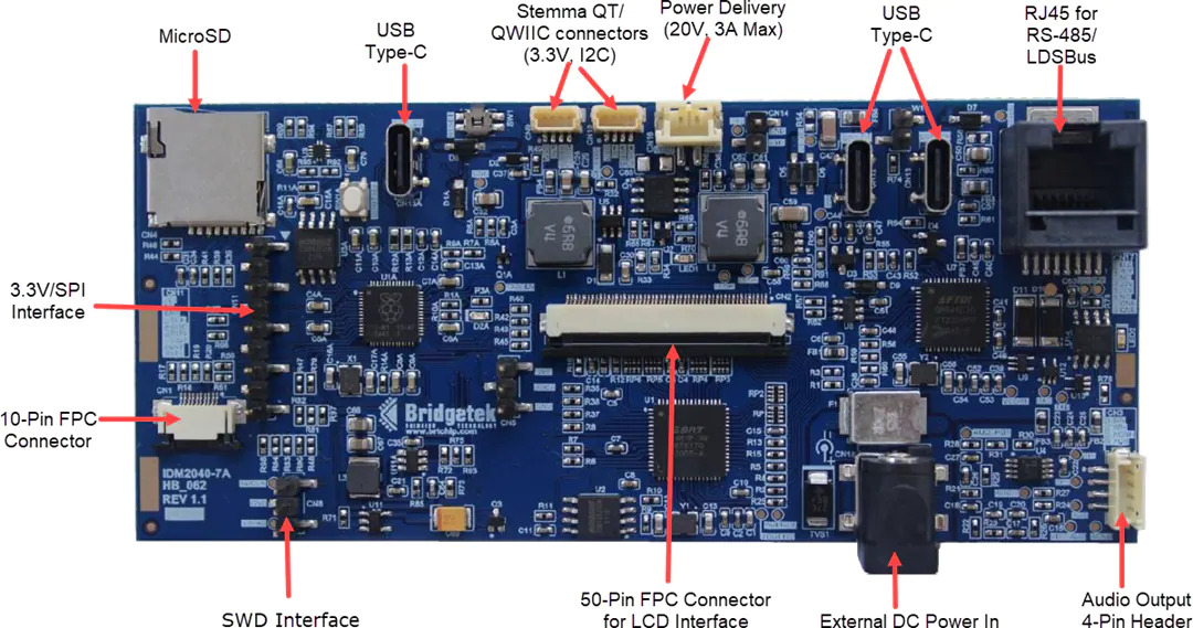
Bridgetek IDM2040-7A Intelligent Display Module features a 7″ 800 x 480 capacitive touch panel. The Display Module is powered by the EVE4 BT817Q Graphics Controller supported by the low-cost, high-performance Raspberry Pi RP2040 Microcontroller. The RP2040 MCU allows easy programming using the CircuitPython or MicroPython libraries. The onboard RS485 transceiver allows communication with Long Distance Sensor Bus (LDSBus) devices or DMX512 devices through Cat 5/6 cables over an RJ45 connector.
The Bridgetek IDM2040-7A Intelligent Display Module can be powered via USB Type-C™ or an external power supply connected to the DC-jack. The Type-C PD port is controlled by the FTDI FT232HP USB Type-C/PD Bridge IC, which features a programmable PD sink profile.
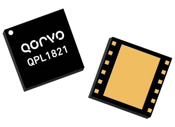
Qorvo QPL1821 75Ω CATV Amplifier is an ultra-linear GaAs (Gallium Arsenide) pHEMT (Pseudomorphic High-Electron-Mobility Transistor) differential RF amplifier offering up to 19dB of flat gain with very low distortion. The QPL1821 features a 50MHz to 1800MHz frequency range providing an ideal solution for Broadband CATV DOCSIS 4.0 applications, such as nodes, amplifiers, and remote PHY devices, as well as Fiber to The Home (FTTH), home gateways, and cable modems. The device is powered by a single 5V supply at 260mA, which provides an output of 63dBmV TCP at a Modulation Error Ratio (MER) of 45dB.
The Qorvo QPL1821 75Ω CATV Amplifier is available in a compact, 12-pin 5.0mm x 5.0mm laminate module well-suited for space-constrained designs.
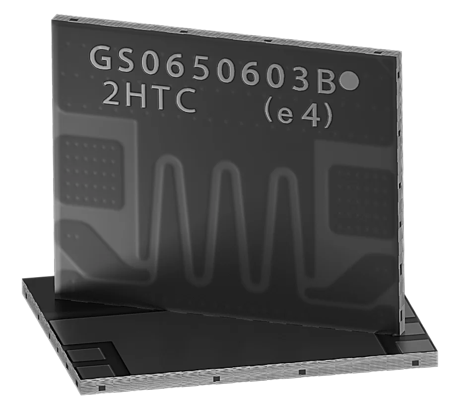
GaN Systems GS-065-060-3 650V Enhancement Mode GaN (Gallium Nitride) Transistor is a power transistor optimized for high current, high voltage breakdown, and high switching frequency. The GS-065-060-3 features an Island Technology® cell layout, reducing the size of the device while transferring substantially more current using on-chip metal. GaNPX® packaging enables low inductance and low thermal resistance in a small package. These features combine to provide very high-efficiency power switching.
The GaN Systems GS-065-060-3 650V Enhancement Mode GaN Transistor is offered in two variants. The GS-065-060-3-B is a bottom-side cooled transistor, while the GS-065-060-3-T is a top-side cooled transistor. Both devices provide very low junction-to-case thermal resistance for demanding high-power applications.
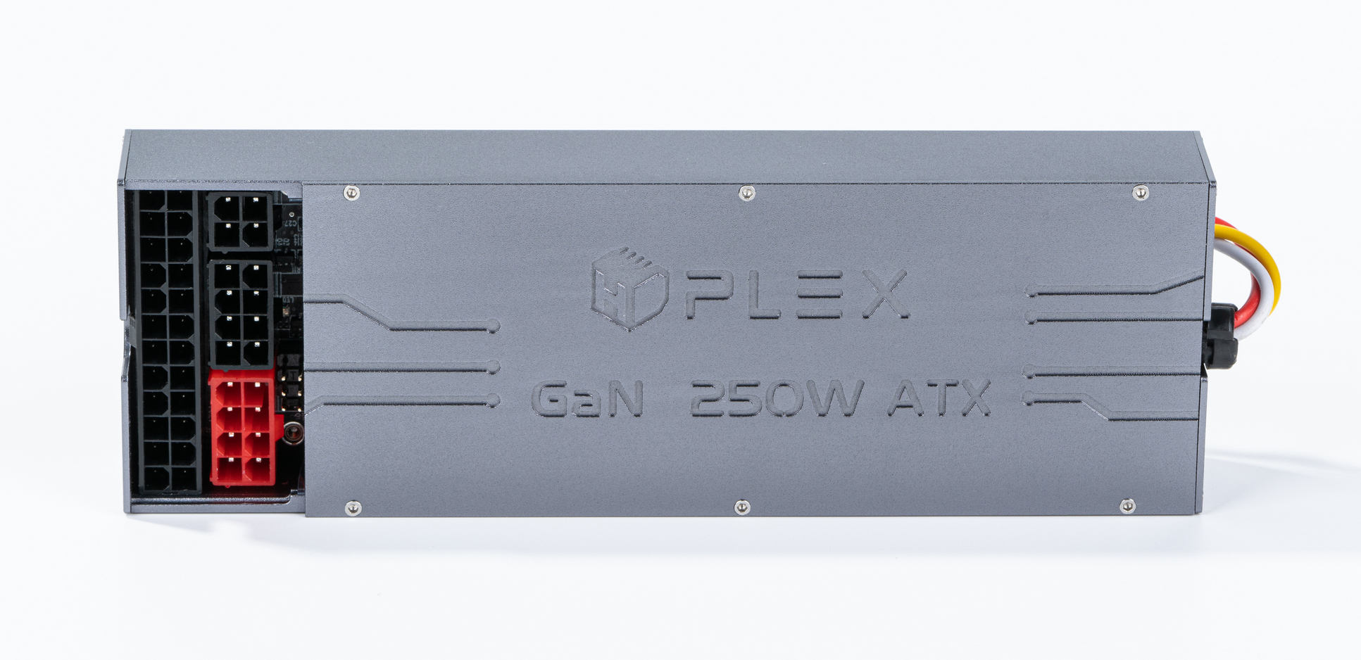
HDPLEX company which is known for its fan-less and compact PCs, reveals its passive GaN AIO (All-In-One) ATX PSU ( Advanced Technology eXtended Power Supply) with an output power of 250W. It makes use of the cutting-edge GaN (Gallium Nitride) technology that can be found in some tiny USB-C power supplies. This compact PSU measures only 170mm x 50mm x 25mm and it works well with applications that have limited space.
The entire HDPLEX unit is just slightly larger and thicker than an average smartphone which makes it a perfect fit for SFF (Small Form Factor) PC configurations. Not only is it the smallest HDPLEX 250W GaN PSU in the world but it also provides a fully passive design that eliminates the requirement for an active cooling solution. This ATX PSU is covered with an aluminum alloy body that helps in quickly dissipate the heat to cool down the system. Since it is a fanless design, under full load it has a robust zero noise operation which makes it a great choice for applications like Home Theater and Recording Lab environments.
Though its size is small, it packs in 1.18W/cm³ super high power density that can effectively break the 1W/cm³ barrier with the help of its cutting edge GaN (Gallium Nitride) chip and a highly advanced LLC+PFC structure. This ATX PSU achieves 94% efficiency at full load while satisfying the Level V Energy Efficiency standard. The PFC stage makes use of two automotive-grade GaN FETs and the LLC stage also uses two automotive-grade GaN FETs. HDPLEX 250W uses four ATX 1KV 8A TTR8MF chips for full-wave rectification and guarantees a stable current for the output stage. It has a 1% Resistors to ensure there is no deviation for every key point in the chain.
HDPLEX 250W GaN ATX PSU Specifications
Wattage: 250W
Input Voltage: 90V-264V 50/60hz
DC Ouput: +3.3V up to 10A | +5V up to 10A | +12V up to 20A | -12V up to 1A | +5VSb up to 3A
Max combined power for +3.3V and +5V – 80 W
Idle Power: <0.4W/0.1W
Noise Level: zero dB operation with fully passive/fanless design
Power Density: 1.18W/cm³
Temperature Range: -10°C – 75°C
PFC+LLC Structure, Level 5 energy efficiency
2x auto-grade GaN FETs on PFC stage and 2x on LLC stage
Three Stage AC input filter to eliminate grid noise
4x ATX 1KV 8A TTR8MF Full-wave rectification
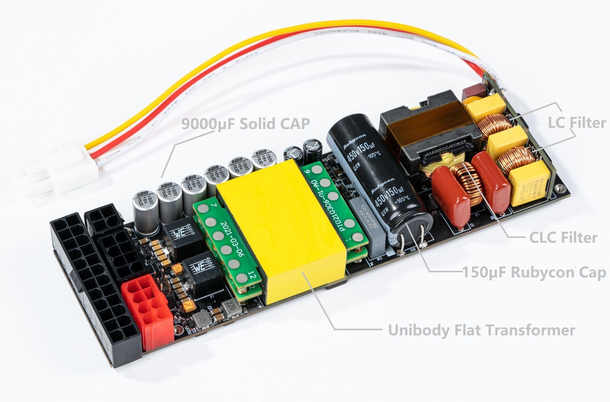
150µF Rubycon filter CAP and 9000µF Solid Cap
Detachable C14 IEC connector to support other AC input for custom projects
If the 250W of power is not enough we can also sync the unit with a second PSU to gain a combined output power of 500W. HDPLEX supports modular ATX output and sync with a second HDPLEX 250W via its sync cable. This configuration can be used to run the motherboard and CPU from one, while the second one could power the graphics card. Furthermore, HDPLEX 250W GaN PSU features a unibody flat transformer that has excellent consistency and eliminates the noise caused by vibration. Its PCB is made out of four 2oz copper layers that are fit for high current applications and swift heat transfer. HDPLEX also has a durable 150µF Rubycon filter capacitor and 9000µF solid caps alongside a three-stage AC filter circuit (2 LC+1 CLC) to eliminate interference from the power grid.
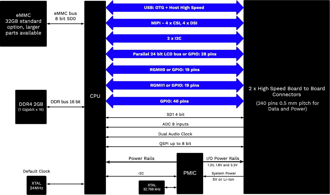
MistySOM is a battery-powered system-on-a-module manufactured by MistyWest, a company known for its engineering products and consultancy services. It is developed to be used for AI-based applications that specifically require high processing capabilities and low power consumption. In the traditional SOMs, this was a tricky combination to achieve, especially with battery-based designs. SOMs were unable to provide low-power applications. Also, in the systems with higher power consumption there was overheating which meant there would be a bulky heat sink. The new MistySOM consumes half the power as the other microprocessors, for the same computer vision tasks. It is built to enable battery-powered computer vision applications and solve the challenging power problems that are common in today’s IoT environments.
It uses the power of Renesas’s series of RZ/V2L processors to meet the demands of modern IoT edge devices, especially for image processing applications. It fits perfectly with their highly capable and energy-efficient AI chips. The Renesas RZ/V2L is a dual-core Arm Cortex-A55 CPU that runs at 1.2 GHz. It also features the Dynamically Reconfigurable Processor (DRP) Technology that allows a vision algorithm to change configurations on the go. MistySOM can provide a reduction in charge cycles and a reduced bandwidth requirement. The DRP-AI exhibits excellent power efficiency and eliminates the need for any additional heat dissipation measures, such as heat sinks or cooling fans, to achieve consistent performance.
Specifications of MistySOM
Low power requirements
Yocto Linux Operating system
AI accelerator
Cortex-A55 (Dual or Single)
Cortex-M33
3D graphics engine (Arm Mali-G31)
Video codec (H.264)
Camera interface (MIPI-CSI)
Display interface (MIPI-DSI)
Two USB2.0 interfaces
Two CAN interfaces
Gigabit Ethernet 2ch
2GB DDR4 RAM
Supports WiFi and Bluetooth interfaces on the I/O board
It is compatible with the Renesas RZ/G2L processor for less demanding applications
Using the RZ/V2L, MistySOM can perform a number of AI computer vision processing such as graph optimization and FP16 quantization. It has the capabilities of performing these processes at high speeds and with a minimal power budget, with the help of its in-built AI accelerator DRP-AI. Moreover, with a dedicated Neural Processing Unit, MistySOM can perform AI computer vision tasks at 50% less power than the other processors available. It delivers high-speed AI inference at low power consumption, backed by the NPU that supports standard ONNX ML models.
A trained ONNX model can be implemented cost-efficiently, enabling customers to implement a variety of AI-based vision applications without requiring an external image signal processor (ISP). The images can be captured through the MIPI-CSI interface and h.264 encoded. This integrated combination allows MistySOM to provide a real-time AI inference engine with hardware-accelerated image processing functions, like color correction and noise reduction. It is ideal for any application that requires object detection and image classification in a small battery-powered system.