StarFive VisionFive V1 RISC-V Single Board Computer on sale for $179

StarFive VisionFive V1 RISC-V Single Board Computer

After the hype around BeagleBoard Foundation’s BeagleV StarFive RISC-V SBC, the cancellation came as a shock to the embedded developers’ space. However, as an alternative to the original RISC-V single-board computer and continuing most of its features, StarFive unveiled the VisionFive V1 late last year— now available for purchase on ALLNET China. The hardware comes with SiFive’s U74 64-bit RISC-V processor core which is comparable to the Arm Cortex-A55 processor.

At the heart of the single-board computer is the StarFive JH7100 system-on-chip tightly integrated with a dual-core RV64GC ISA U74 high-performance RISC-V application processor clocked at a frequency of 1.0GHz, capable of supporting a fully-featured operating system such as Linux. The SoC comes with Vision DSP Tensilica-VP6 for computing vision at 600MHz (VPU), an NVIDIA Deep Learning Accelerator, and a neural network engine. Incorporating 8GB of LPDDR4 memory, but no onboard storage, however, the manufacturer provides a MicroSD card slot. Even the LPDDR4 memory is divided into 2x 4GB clocked at 2800MHz, which restricts performance, unlike the totally integrated 8GB SDRAM.

Of course, with all the Neural Network Engine, NVLDA Engine and DSP, the board is a powerful piece of hardware for human-machine interface, smart home tech, surveillance, NAS, and even multimedia applications. The board comes with H.264/H.265 video decoder supporting up to 4Kp60 and dual-stream decoding up to 4Kp30 making it one of the most affordable choices for live streaming multimedia implementations.

StarFive VisionFive V1 SBC

It is very important to support various wireless connectivity protocols to take the benefit of the vision processing unit and neural network engine as most of the applications are deployed at the edge. To assist with such projects, the single board computer comes with 2.4GHz Wi-Fi IEEE802.11b/g/n and Bluetooth 4.2 (BLE) wireless connectivity. Also, the onboard Gigabit Ethernet port lets the user share the mobile data connection with the VisionFive V1 SBC over the wired network connection.

On the software side, as mentioned earlier, the hardware is capable of running the Linux operating system with software compatibility for U-Boot Bootloader, GRUB2 Bootloader, Linux Kernel, OpenEuler, Fedora, OpenSBI Firmware. As of writing, the VisionFive V1 RISC-V Single Board Computer starter kit is available for purchase at $179.00 which includes the StarFive VisionFive V1 SBC, Heatsink with fan, and a 32GB SD card with pre-flashed Fedora OS.

Analysis

The hype around BeagleBoard Foundation’s BeagleV StarFive RISC-V SBC explains the demand for StarFive VisionFive V1 SBC due to its powerful system-on-chip and improved functionalities for most hobbyist and industrial projects. The board is seen as a general-purpose SBC reducing its capability to be exploited for one domain, like vision processing. Even though the hardware supports H264 and H265 video decoder, for live video streaming, the hardware requires more memory to process. SDRAM is split into 2 4x RAM, which limits performance and might not sustain processing for high video graphics.

Cat M1 vs Cat 1 vs Cat 4: Connectivity for Telematics

Through increased adoption of data-driven telematics use cases in vehicles, there has been a rising need for telematics edge hardware across a range of vehicles. Telematics and connected vehicle solutions help unlock value across a range of vehicle types: passenger cars, heavy duty trucks, electric vehicles, boats, with the list growing day by day.

Different applications require different data processing and connectivity architectures – A few applications require more edge processing with intelligence on the device, while a few use cases require all data to pushed on to the cloud platforms to build on the analytics and dashboards.

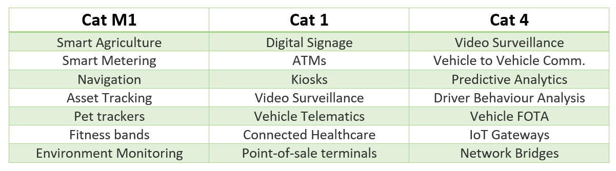
The improvement in the connectivity landscape has enabled vehicles to be connected to the internet. Cellular technology is available from Cat 0 to Cat 19, however, the technology most suited and commonly used in telematics and connected mobility solutions are Cat M1, Cat 1 and Cat 4. A more detailed insight into these 3 connectivity technologies is given below.

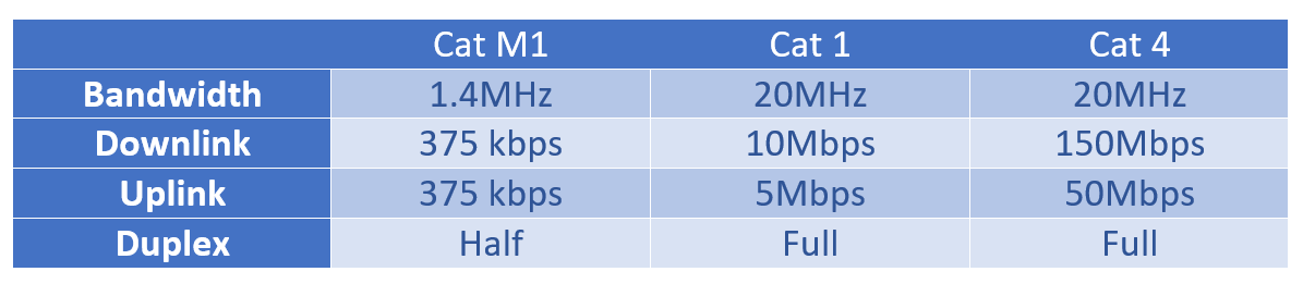
A Comparison of throughput: Cat M1 vs Cat 1 vs Cat 4

Cat M1, which also goes by the name LTE Cat M1 originally was designed specifically for IoT Solutions, with an average upload and download speed of 375 kbps. There is a trade-off between lower data range and the signal rate, where in the lower data rates enable the signal to travel further, allowing for devices to be positioned in remote locations.

Cat 1 supports higher data throughput of 10Mbps, enough for a majority of telematics and IoT applications. Cat 1 offers better global coverage while supporting low latency for wake-up applications. The major attraction is that it’s already standardized, and more importantly, it’s simple to transition into the Cat 1 network

Cat 4 modems can scream data at rates of up to 50Mbps upload and 150Mbps download speeds, which are essentially the same speeds consumers get on their smartphones.

Coverage and Cost: Cat M1 vs Cat 1 vs Cat 4

Cat M1 is compatible with the existing LTE network, providing a slight advantage over the other options available. However, Cat M1 support is not widely available yet around the world with network operators including in their roadmap for launch soon. Taking the advantage of technological maturity and global coverage of 4G network, LTE Cat 1 has a strong and reliable network foundation to empower various IoT applications and scenarios. Cat 1 is available today and widely supported by carriers worldwide In fact, by the end of 2025, NB-IoT and Cat M1 are expected to make up 52% of all cellular IoT connections, according to the Ericsson Mobility Report in November 2019.

Since the Cat M1 band is also the same across geographies, a single SKU can support global coverage. In case of applications, where the vehicle is travelling through geographies, Cat M1 is the right connectivity module to choose.

LTE Cat 1 IoT solution presents its advantages with its amazing cost performance in the medium rate market. However, there are 2 costs to be considered – The module costs as well the recurring network costs. Cat M1 and Cat 1 can be considered as low-cost options, both from the module costing perspective as well as the recurring network costs. Cat 4 is slightly more expensive but can sometimes be the right module to choose dependent on the throughput requirements. The price difference between Cat 1 and Cat 4 modules are getting narrower through economies of scale, as module and chip vendors are beginning to consolidate requirements across customers and applications.

Use Cases: Cat M1 vs Cat 1 vs Cat 4

If your IoT use case involves maintaining an “always-on” connection between your devices and your application cloud, then a Cat 1 or Cat 4 modem is better suited for your device.

When Cat M1 technology is fully deployed, LTE for IoT will spread to the numerous types of very low throughput, very low power consumption applications such as industrial sensors, asset trackers, or wearables that wake up periodically to deliver only very small amounts of data and then go back to sleep. Cat M1 was designed primarily for efficiency. If the end application needs transmitting large data, constant connection, or high speed, then Cat M1 won’t be viable.

Cat 1 is believed to be the ideal solution for scenarios that are not dependent on high-speed data transmission but still require the reliability of the 4G network, and Cat 4 finding in a fit where there are no power budget constraints, and a requirement for high data throughput.

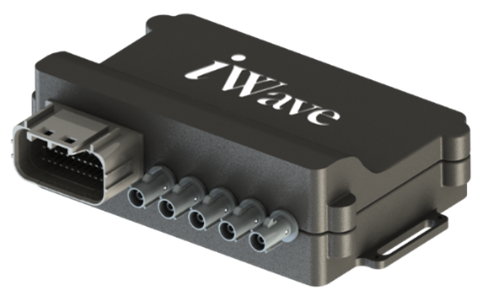
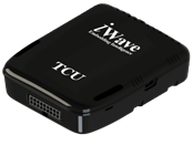
iWave Telematics Portfolio: Cat M1 & Cat 4 Telematics Units

Enabling customers to unlock value across a range of connected fleet, iWave supports customers with a Telematics Control Unit and Telematics Gateway. The telematics hardware is compatible with Cat M1 networks or can be configured to support Cat 4 networks, with the modem configuration an assembly configuration, making the device compatible to multiple connectivity technologies.

Integrating a pre-certified connectivity modem, which has been certified across geographies such as FCC, CE, GCF & TELEC, and network operator certifications such as VERIZON, AT&T, TELSTRA, VODAFONE makes the iWave telematics unit easier to certify dependent on the geographic certification requirements.

The telematics hardware is integrated with 3 CAN Ports, IMU Sensors, Ethernet, Analog Inputs with the support for various wireless technologies such as LTE, Wi-Fi, and Bluetooth. iWave supports telematics service providers with rugged and reliable telematics hardware. We design and manufacture telematics control units, telematics gateway and V2X Connectivity Solutions to cater to the growing telematics applications.

Summary

While there is no one fit all modem for all telematics use cases, A decision considering cost, power consumption and throughput must be taken based on the end application. Since data rate requirements and power consumption are in most cases pre-determined by end application, The type of network connectivity you would need should be decided based on your desired functionality, not by the price of the LTE modem.

There are a wide range of telematics use cases, ranging from personalized infotainment, fleet management, route scheduling and predictive maintenance. Different use cases require different connectivity modems and varying levels of processing power on the edge.

Cat M1 offer many benefits, but currently have some limitations, namely, still an emerging technology, and coverage is still limited globally. Cat 1 and Cat 4 are the dominant connectivity technologies at present, which can be chosen based on the throughput and end application.

To get in touch with iWave for enquiries and any further information, you can reach us at mktg@iwavesystems.com.

Audio Line Receiver using INA134

The project described here is a differential line receiver consisting of high-performance INA134 OPAMPs with on-chip precision resistors. The project is fully specified for high-performance audio applications and has excellent AC specifications, including low distortion (0.0005% at 1kHz) and high slew rate (14V/µs), assuring good dynamic response. In addition, wide output voltage swing and high output drive capability allow use in a wide variety of demanding applications. The INA134 on-chip resistors are laser trimmed for accurate gain and optimum common-mode rejection. Furthermore, excellent TCR tracking of the resistors maintains gain accuracy and common-mode rejection over temperature. Operating power supply ±4V to ±18V (8V to 36V total supply).

This project is used in combination with the DRV135 Audio-Balanced Line Driver as the transmitter. Together they offer a complete solution for transmitting analog audio signals without degradation over a long distance.

Features

  • Power Supply +/-12V (SUPPLY RANGE: ±4V to ±18V)
  • Low Distrortion: 0.0005% at f = 1kHz
  • High Slew Rate: 14V/µs
  • Fast Settling Time: 3µs to 0.01%
  • Low Quiescent Current: 2.9mA max
  • High CMRR: 90dB
  • Fixed Gain= 0dB (1V/V)
  • PCB Dimensions 39.37 x 360.48 mm

Applications

  • Audio Differential Line Drivers
  • Audio Mix Consoles
  • Distribution Amplifier
  • Digital Effects Processors
  • Hi-Fi Equipment’s

Schematic

Parts List

NO.QNTY.REF.DESC.MANUFACTURERSUPPLIERPART NO
11CN13 PIN SCREW TERMINAL PITCH 5.08MMPHOENIXDIGIKEY277-1248-ND
21CN23 PIN SCREW TERMINAL PITCH 5.08MMPHOENIXDIGIKEY277-1248-ND
31CN36 PIN MALE HEADER PITCH 2.54MMWURTHDIGIKEY732-5319-ND
42C1,C510uF/20V SMD TANTLUM SIZE 1210/1411KYOCERADIGIKEY478-12567-1-ND
52C2,C60.1uF/50V SMD SIZE 0805MURATA/YAGEODIGIKEY
63C3,C4,C7470PF/50V SMD SIZE 0805MURATA/YAGEODIGIKEY
71D1LED 3MM THTAMERICAN OPTO DIGIKEY2460-L314GT-ND
81R149.9E 1% SMD SIZE 0805MURATA/YAGEODIGIKEY
91R21.5K 5% SMD SIZE 0805MURATA/YAGEODIGIKEY
101U1INA134 SOIC8TIDIGIKEYINA134UA-ND
CAPACITOR C1, C5 CAN BE REPLACED WITH10uF/25V ELECTROLYTIC CAPACITOR

Connections

Application Diagram

Transmitter/Receiver Diagram

Gerber View

Photos

Video

INA134 Datasheet

Audio Line Driver using DRV135 with Balanced Output

The project presented here is a differential output amplifier that converts a single-ended audio signal input to a balanced output pair. This balanced audio project consists of high-performance OPAMPS with on-chip precision resistors. They are fully specified for high-performance audio applications and have excellent AC specifications, including low distortion (0.0005% at 1 kHz) and high slew rate (15 V/µs). The board is based on DRV135 from Texas Instruments.

The on-chip resistors are laser-trimmed for accurate gain and optimum output common-mode rejection. Wide output voltage swing and high output drive capability allow use in a wide variety of demanding applications. They easily drive the large capacitive loads associated with long audio cables.

This project is used in combination with the Audio Line Receiver using INA134 as the receiver. Together they offer a complete solution for transmitting analog audio signals without degradation over a long distance.

Features

  • Single-Ended Audio Input and Balanced Output
  • Low Distortion: 0.0005% at f = 1 kHz
  • Wide Output Swing: 17Vrms into 600 Ω
  • High Capacitive Load Drive
  • High Slew Rate: 15 V/µs
  • Wide Supply Range: ±4.5 V to ±18 V @ 15mA without Load
  • Low Quiescent Current: ±5.2 mA
  • Companion to Audio Differential Line Receivers: INA134
  • Improved Replacement for SSM2142
  • PCB Dimensions 48.26 x 36.20 mm

Applications

  • Audio Differential Line Drivers
  • Audio Mix Consoles
  • Distribution Amplifier
  • Digital Effects Processors
  • Hi-Fi Equipment’s

Schematic

Parts List

NO.QNTY.REF.DESC.MANUFACTURINGSUPPLIERPART NO
11CN13 PIN SCREW TERMINAL PITCH 5.08MMPHOENIXDIGIKEY277-1248-ND
21CN23 PIN SCREW TERMINAL PITCH 5.08MMPHOENIXDIGIKEY277-1248-ND
31CN36 PIN MALE HEADER PITCH 2.54MMWURTHDIGIKEY732-5319-ND
42C1,C447uF/25VKEMETDIGIKEY399-18446-1-ND
52C2,C50.1uF SMD SIZE 0805MURATA/YAGEODIGIKEY
63C3,C7,C1010uF/50V NON-POLARNICHICONDIGIKEY493-10835-1-ND
73C6,C8,C9470PF/50V SMD SIZE 0805MURATA/YAGEODIGIKEY
84D1,D2,D3,D41N4007 SMD SMC DIODE SOLUTIONDIGIKEY1655-1N4007FLCT-ND
91D5LED SMD SIZE 0805LITE ON INCDIGIKEY160-1427-1-ND
101R11.5K 5% SMD SIZE 0805MURATA/YAGEODIGIKEY
111U1DRV135 SOIC8TIDIGIKEYDRV135UA-ND

Connections

Application Diagram

Transmitter/Receiver Diagram

Gerber View

Photos

Video

DRV135 Datasheet

PCBWay added more solder mask colors and includes a new transparent design

Some of the well-known PCB layout design software are Eagle Software, Altium Designer 22 and KiCAD. However, Altium Designer 22 remains a market leader despite its expensive full-suite license. For embedded electronic manufacturers inclined towards adopting open-source technologies, choose KiCAD as a PCB design tool that recently announced the release of KiCAD version 6.0.0 that incorporates a new interface and improved PCB design experience. Even hardware enthusiasts and project designers are willing to use KiCAD over other PCB design tools and all this boils down to fabrication and assembly of the designed PCB. One of the top choices is PCBWay as it offers a large number of benefits such as customization and bulk discounts.

Today, we will be understanding why PCBWay recently added more customization options for PCB makers. On September 13, 2021, the PCBWay team released a blog post titled, “PCBWay New Solder Mask Colors – Pink, Gray, Orange and Transparent” suggesting the addition of new solder mask colors– understanding the client’s demand as they as “we listened and learned”. Before this announcement, the team has already added some new colors like matte black, matte green and purple, however, as the company quotes, “that doesn’t seem to satisfy everyone” so here comes more solder mask colors to include pink, orange, gray and transparent to the existing list of popular green, red, yellow, blue, white, and black. Interestingly, PCBWay provides these customization options only for the Advanced PCB option and is not included in the Standard PCB specification selection.

PCBWay Color Customization Options

As we look deeper into what makes a solder mask so important as part of PCB fabrication and does a different color solder mask aid your performance or heat dissipation. In simple terms, a solder mask is a material that covers an area on the PCB where insulation is required that is usually applied to the copper traces for protection against oxidation and to prevent solder bridges from closely spaced solder pads. In intricate soldering design, closely spaced solder pads can incur errors short-circuiting the entire design and requires a gap where the solder does not stay and an unintentional electrical connection between two conductors does not take place. The most commonly used solder mask is green in color, but as mentioned earlier, there are several new options arising. To manufacture these solder masks, there are various materials with which the cost of PCB design fluctuates, with epoxy liquid being the lowest-cost solder mask. Other types are liquid photoimageable solder mask inks and dry film photoimageable solder masks. However, as the evolution of PCB substrate material takes place, FR-4, named fiberglass-reinforced epoxy-laminated sheets, has become a widely popular choice among electrical engineers and designers.

Analysis

All this is good, but does the color make any difference to the performance of circuit boards? Well, technically, NO, but it depends on the designers who want different color customizations for their PCBs. The most common answer would be, ‘they want to try different colored PCB manufacturing for custom applications, and avoid traditional Green PCB’. Whatever may be the reason, “clients” as mentioned by PCBWay, are looking for more color options than the existing long list.  So if you want your PCB to look fancier than ever before and make it stand out, then you can try the PCBWay new solder mask and silkscreen colors from the Advanced PCB page.

In the announcement, PCBWay also added a new black core PCB material, which is a Black FR-4 and will cost extra after the order is reviewed.

For more details, head to the official blog post. If you are interested in customization of your PCB design, look for Advanced PCB specifications.

AAEON Announces BOXER-8260AI and BOXER-8261 AI@Edge Embedded BOX PCs Powered by NVIDIA Jetson AGX Orin System on Modules

With the announcement of the NVIDIA® Jetson AGX Orin™ developer kit, AAEON is excited to utilize the many benefits that such a powerful system-on-module (SOM) can bring to its own product lines. With the same form factor and pin compatibility as the NVIDIA Jetson AGX Xavier™, but with an improvement from 32 TOPS to 275 TOPS, the NVIDIA Jetson AGX Orin is set to make it easier than ever to develop faster, more sophisticated AI applications.

AAEON is therefore pleased to announce two upcoming products available in Q4 which will feature the Jetson AGX Orin 32GB and Jetson AGX Orin 64GB as their respective processor modules: the BOXER-8260AI and BOXER-8261 AI@Edge Embedded BOX PCs. Both products will feature the NVIDIA JetPack™ 5.0 SDK to support the full Jetson software stack to help in the development of AI applications in areas such as high-end autonomous machinery.

With two NVIDIA deep learning accelerators (NVDLA), along with a 32GB 256-bit system memory, the BOXER-8260AI will provide the perfect device for vision-based AI applications. Moreover, its expansive I/O options include 12 RJ-45 slots for PoE, along with DB-9 slots for CANbus and six DIO.

The BOXER-8261AI is equipped with 64 GB 256-bit system memory and 64 GB eMMC storage. The BOXER-8261AI also offers 2 Giga LAN RJ45 ports, alongside 5 USB slots and a micro-SD card slot for additional storage. The AI performance capabilities of the Jetson AGX Orin, based on the NVIDIA Ampere GPU architecture, are 8x that of the Jetson AGX Xavier, giving users unprecedented access to more powerful and efficient AI inferencing capabilities, along with increased processing speed. Further boosting the Jetson AGX Orin is the architecture’s up to 2,048 CUDA cores and 64 third-generation Tensor Cores, in comparison to its predecessor’s Volta architecture, which had 512 CUDA and 64 Tensor Cores.

In addition, the Jetson AGX Orin developer kit’s 12-core Arm Cortex-A78AE v8.2 64-bit CPU shows significant improvements over the previous model, with an increase from eight Carmel cores to 12 A78 cores for a more powerful processing unit.

As is already apparent from the BOXER-8260AI and BOXER-8261’s potential applications, AAEON customers will benefit tremendously from NVIDIA’s innovation, with AAEON’s ODM and OEM expertise utilizing the adroitness of the Jetson AGX Orin in facilitating AI application deployment. The combination of the Jetson AGX Orin SOM’s sophisticated GPU, its integrated AI software, and deep learning accelerators will ensure AAEON customers have access to the most powerful computing options when it comes to realizing their AI edge concepts.

A further benefit to AAEON customers is that the Jetson AGX Orin developer kit features the same 699-pin form factor module as previous modules, ensuring compatibility with AAEON carrier boards loaded with existing NVIDIA modules of the same configuration, allowing for smooth migration to power existing AI edge applications.

For more information about the NVIDIA® Jetson AGX Orin™ developer kit, please follow visit their product page: https://www.nvidia.com/en-us/autonomous-machines/embedded-systems/jetson-orin/

Autonomous USB Type-C Power Delivery for sink applications

ROHM’s USB Type-C power delivery provides for quick and easy design and implementation of USB Type-C PD for sink applications (UFP)

ROHM’s ICs are members of their proven full-featured USB Type-C power delivery (PD) controller portfolio. They allow quick and easy design and implementation of USB Type-C PD for sink applications (UFP). Supporting the full suite of UFP features, they are verified as compliant and do not need an external MCU. They handle all functions required by UFP, including dead battery, plug-in, and detach detection. The devices provide control of the required power path NMOS FETs which provide power isolation and reverse current protection. The voltage range and sink power settings are selectable by GPIOs.

Features

  • 32Bit ARM® Cortex®-M0 Processor Embedded
  • USB Type-C Specification Ver.1.3 Compatible
  • USB PD Specification Ver.3.0 Compatible
  • Integrated VBUS N-ch MOSFET Switch Gate Driver
  • Integrated VBUS Discharge Switch
  • Protection Voltage of CC Pins is 28V
  • Supports Dead Battery operation
  • I²C Interface for Host Communication

Applications

  • Any electronic product that requires USB Type-C PD charging as a power sink
  • Smart/portable speakers
  • Drones
  • External storage

more information: https://www.rohm.com/products/interface/usb-type-c-power-delivery/controller/bd93f10mwv-product

Rohde & Schwarz at DesignCon 2022 presents latest innovations for high-speed digital applications

At DesignCon 2022, Rohde & Schwarz will showcase live demos covering industry trends in cooperation with industry experts such as Samtec, ataitec, Clear Signal Solutions, and more.

At DesignCon Rohde & Schwarz is demonstrating a mix of unique solutions for high-speed digital applications. High-speed digital interfaces are at the core of all electronic designs. Increasing data rates and growing integration density create new challenges for designs at the IC, board and system level. At the Rohde & Schwarz booth, demos like MGBase-T1 Compliance, USB 3.2 Compliance, and an enhanced PCIe Trigger/Decode demo will be available for show attendees to experience.

As one of the highlights, Rohde & Schwarz will demonstrate the R&S ZNA high-end vector network analyzer (VNA) which features models up to 67 GHz. This extends the VNA’s industry leading performance and unique hardware architecture to high frequency applications. The R&S ZNA will showcase a live demonstration including 112 Gbps PAM4 Channel Analysis and PCIe Gen 6 Channel Analysis. In another highlight demo, the R&S ZNBT40 vector network analyzer covering up to 40 GHz will demonstrate the test of a 400GBASE-CR4 cable assembly according to IEEE 802.3ck with the R&S ZNrun Ethernet Compliance Automation tool. In addition, the R&S RTO6 Oscilloscope will showcase a live demonstration of power integrity measurements of PDN impedance.

Rohde & Schwarz will be exhibiting at DesignCon in booth 1049 at Santa Clara Convention Center on April 5-7, 2022. Open to all attendees on April 6, Rohde & Schwarz is sponsoring a day of complimentary technical seminars by both Rohde & Schwarz product experts and other industry experts from ataitec and Clear Signal Solutions. Beginning at 8 a.m. in the Great America Meeting Room 2, the technical seminars will cover topics such as power integrity measurement fundamentals, Automotive Ethernet, and more. For those who are unable to attend DesignCon 2022, all technical seminars will be available online following DesignCon.

For more information on where to find the technical seminars, and live updates from DesignCon 2022, follow Rohde & Schwarz solutions for Electric Design on LinkedIn .

1200V High-Current Half-Bridge using FAN73912

The project presented here is designed for high-voltage and high-speed driving for MOSFETS and IGBTs that operate up to +1200V. The project consists of a FAN73912 gate driver chip and 2 x IGBTs, DC bus capacitors, current sense resistor for current feedback etc. The advanced input filter of HIN provides protection against short-pulsed input signals caused by noise. An advanced level-shift circuit offers high-side gate driver operation up to VS=-9.8 V (typical) for VBS=15 V. The UVLO circuit prevents malfunction when VCC and VBS are lower than the specified threshold voltage. R8 is the current sense resistor.

1200V High-Current Half-Bridge using FAN73912 – [Link]

High Current Half-Bridge with Over Current & Voltage Feedback for Step Down DC-DC Converter

This project enables the user to create a high current DC-DC converter. The project consists of a high current inductor, high current low voltage 2 x MOSFETs, half-bridge driver LT1158 chip, voltage feedback using onboard R9 and R10 resistor dividers, shunt resistor for overcurrent shut-down. The project has all the required components to create a high current step-down DC-DC converter, refer to the datasheet of LT1158 chip for components selection. The Half-bridge requires a PWM input signal, Arduino or another microcontroller/DSP can be used as a host to generate PWM signal and control enable and fault conditions.

High Current Half-Bridge with Over Current & Voltage Feedback for Step Down DC-DC Converter – [Link]

TOP PCB Companies