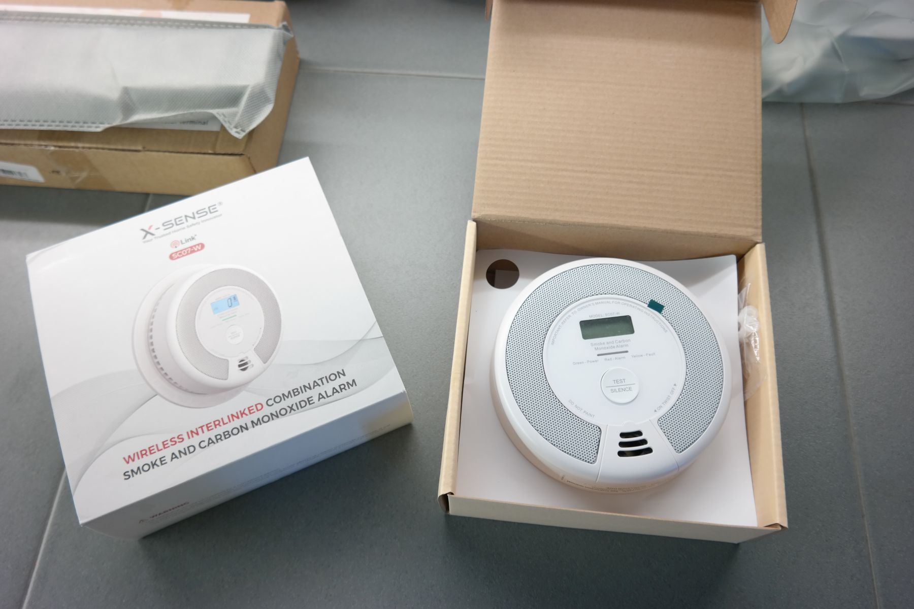
X-Sense Wireless Interconnected Combination Smoke and Carbon Monoxide Detector Review

Introduction

Quality of air in enclosed places, especially homes are in recent times, thankfully, becoming a prominent source of concern because of its severe health implications, and several home automation and safety companies are stepping up to the plate, developing smart and ingenious sensors that help detect an increase in the level of different pollutants, like Carbon Monoxide. One of those companies, is the fast-rising, home automation/security solutions manufacturer; X-sense who recently released the SC07-W Combined smoke and carbon monoxide detector.

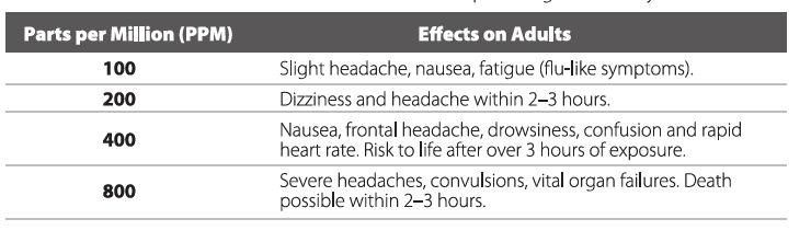
Carbon monoxide is odorless, tasteless, and invisible. A silent killer, exposures to as little as 100 ppm could lead to nausea, fatigue (flu-like symptoms), while exposures to high concentrations like 800 ppm could result in vital organ failures and possible death within 2-3 hours. Smoke on the other hand is a double threat. Asides from heralding fire and the destruction to property and life, it also has choking and nausea-causing effects which could lead to death. These among other reasons make the detection of smoke and tracking the presence of CO in enclosed spaces so alarms are quickly raised, a very important feature for any home.

To detect the CO levels in the air, SC07-W makes use of an electrochemical sensing technology that facilitates early detection of rising CO levels (able to detect CO Particles of around 400 ppm within 4-15minutes) giving users the opportunity to take preventive measures early.

For smoke, the SC07-W system uses a photoelectric detection technology that has been proven to be generally more sensitive than the popular ionization-based approach found in most devices. Thanks to the Photoelectric system, the SC07-W is effective in detecting large particles which tend to be produced in great amounts by smoldering fires which come from slow-burning sources like cigarettes burning in couches or beddings and other similar scenarios, which could smolder for hours before bursting into flame.

Typical home smoke and/or carbon monoxide detectors on the market are plagued with a number of issues ranging from the battery and sensor-related failures, to alarms being confusing and not loud enough. However, one look at the SC07-W reveals it was designed to overcome these challenges.

A big part of the SC07-W is their interconnectivity. Multiple units of the SCO7 can be networked together in such a way that when high levels of CO or smoke are detected in one room or area, the alarms in the other rooms or areas are triggered, ensuring the alarms are heard and the situation is addressed as soon as possible. A personal favorite application of the interconnectivity feature is the ease of expanding the deployment as it allows users to connect up to 24x SC07-W (and other compatible devices from X-sense), making it easy to increase your number of devices and covering more parts of the home.

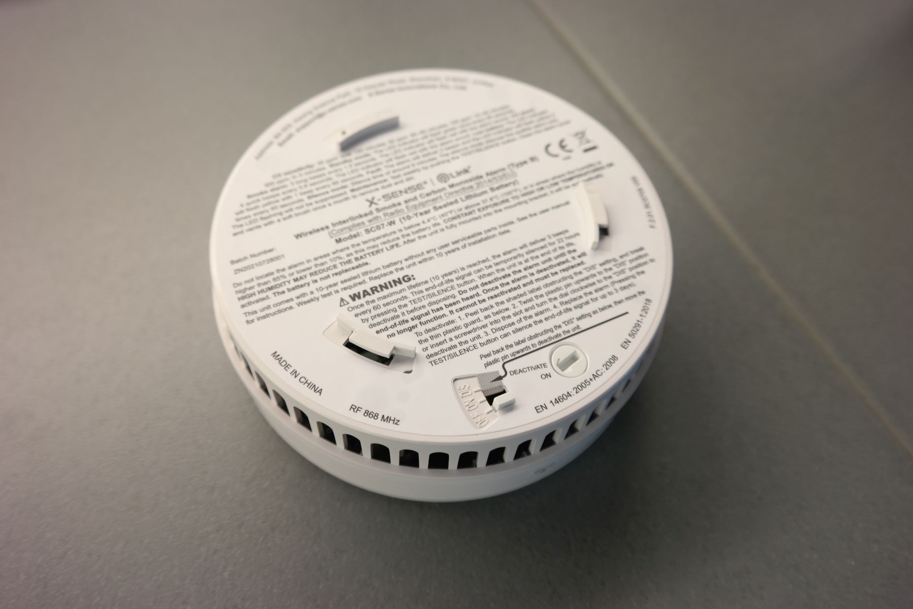
For battery reliability, the SC07-W features a built-in lithium battery, which thanks to the efficiency of the electronics and low-power features of the RF comms module, is rated to last for 10-years, the same number of years as the devices lifetime. This ensures users don’t have to worry about charging or replacing the batteries, avoiding scenarios where the system’s sensitivity fails due to low battery or users forgetting to replace them. According to the manual. at the device’s end of life or the event of a low battery or failure, the alarm will beep once to thrice, every minute and the LED indicator on the device will start flashing yellow, all to let the user know its time to change the unit.

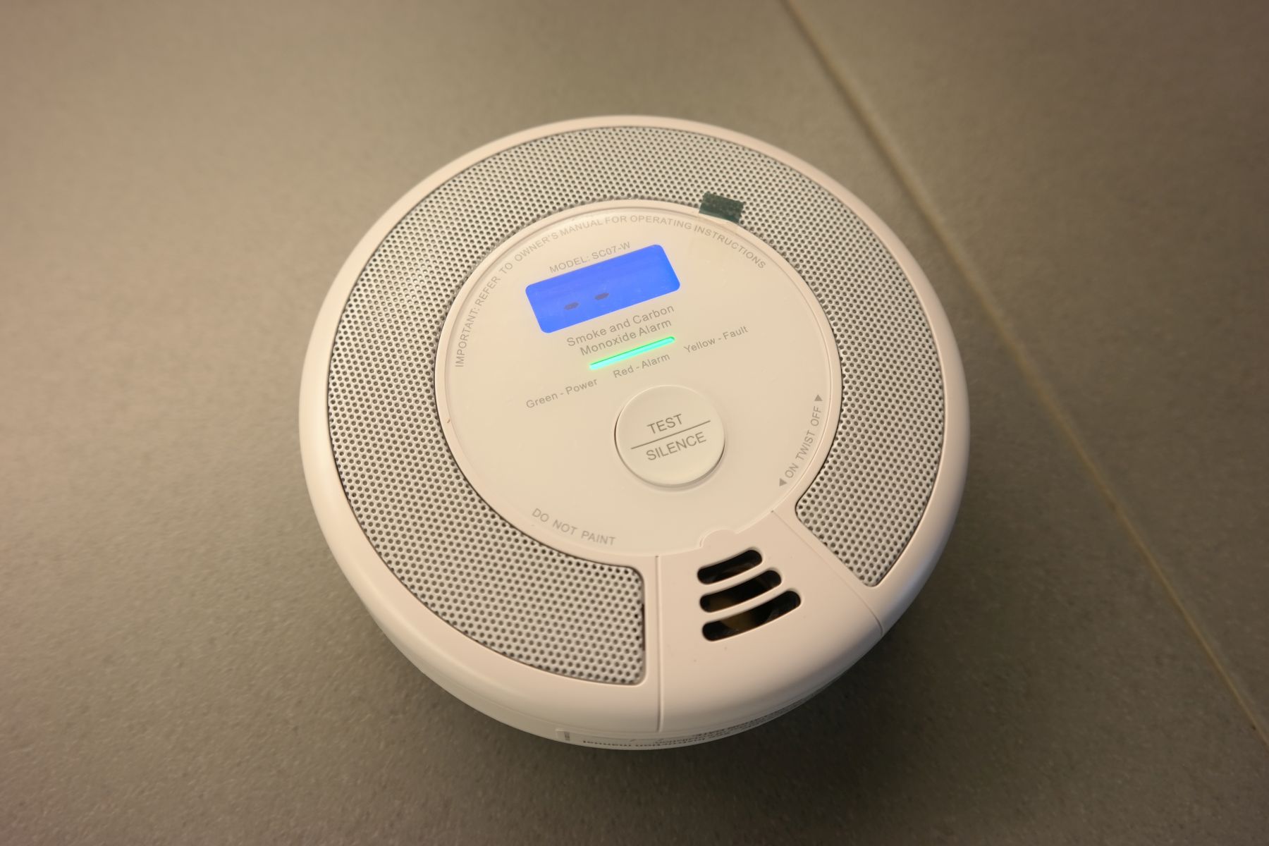
The Alarm system in X-sense SC07-W is sophisticated in that the buzzer sounds in a way that allows users to easily understand and determine the situation at hand. Thanks to the interconnectivity of the alarms, when smoke or increasing CO level is detected by one device, an alarm will be raised by all other connected devices, however, with a sound and led backlight pattern that is slightly different from that of the device in the area where the situation is occurring, to allow users easily pinpoint where the issue is.

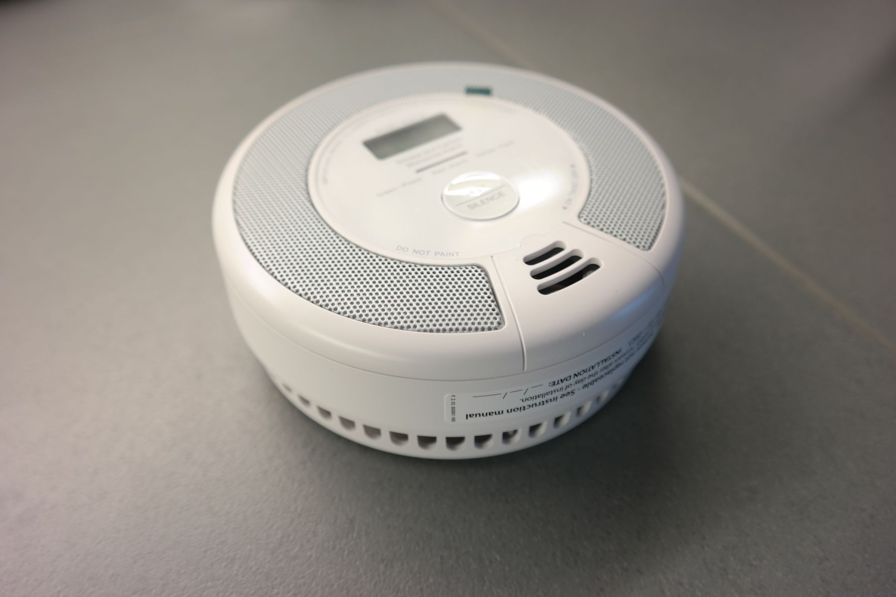
To allow users to see the state of air in their home at all times, and further make it easy to understand what is going on when an alarm goes off, the SCO7 comes with a clear and easy-to-read LCD which indicates real-time CO concentrations (30-999 ppm), battery status, and the alarm’s working status, allowing you to know what’s going on, at a glance.

While the SC07-W comes with a remote, and a button on the device, that can be used to silence the system, an unguided silence mode is a dangerous feature in an alarm system. This is why even when silenced unless the situation has dispersed, the alarm will come back up after some minutes.

Some highlight specifications of the SC07-W are provided below:

Operating Life 10 years
Power Source 3 V CR123A lithium battery (non-replaceable)
Sensor Type Smoke: photoelectric; CO: electrochemical
Safety Standards EN 14604:2005, EN 50291
Standby Current < 6 µA (avg.)
Alarm Current < 60 mA (avg.)
Operating Temperature 40–100°F (4.4–37.8°C)
Operating Relative Humidity 10%–85% (non-condensing)
Alarm Loudness ≥ 85 dB at 10 ft (3 m)
Silence Duration Smoke: ≤ 9 minutes; CO: ≤ 6 minutes
Display LCD
Indicator Light LED (red/yellow/green)
Color White
Material ABS/PC
Installation Method Screw fixings and mounting bracket supplied
Usage Indoor use only
Product Weight 0.66 lb (300 g)
Product Dimensions 5.7 x 5.7 x 2.0 inches (146 x 146 x 51 mm)

A recommendable solution, the SC07-W is at the time of this writing available for sale on X-Sense’s website for $39.99 while a pack of 6 is available on Amazon for $239.

More information on the SC07-W combined smoke and CO detector can be found on the product’s page on X-sense’s website.

Discount Code

Code: CHTG0120 (20% off all products) at x-sense.com

DC-HV DC Converter – 200V @ 20mA Output with 12V DC Input

This is a low-cost DC-HV DC converter built using TL3843 Low-Power Current-Mode PWM Controller from TI. Screw terminal connectors are provided for input and output, onboard LED D1 indicates the input supply. The project provides 200V DC @ 20mA output from 12V DC supply input.

Note: Output of this project is 150V @ 50mA DC to 200V @ 20mA DC, this project also can provide lower voltage outputs, read TL3843 data sheet for configuration.
HIGH VOLTAGE: Dangerous voltage exists until power is off. Wait at least 1 minute after the input power is disconnected before touching the board and discharge HV capacitors.

Features

  • Operating Power Supply 12V DC @ 1A (Range 10V to 15V DC)
  • Output 150V DC @ 50mA to 200V DC @ 20mA
  • Operating Frequency 40Khz
  • Over Current Protection
  • D1 Power LED
  • Screw Terminal Connectors for Input and Output
  • PCB Dimensions 61.28 x 36.04 mm

Schematic

Parts List

NO.QNTY.REF.DESC.MANUFACTURERSUPPLIERPART NO
12CN1,CN22 PIN SCREW TERMINAL PITCH 5.08MMWURTHDIGIKEY277-1247-ND
21C1470uF/25V ELECTROLYTICPANASONICDIGIKEY10-EEU-TA1E471S-ND
31C20.1 uF/50V SMD SIZE 0805MURATA/YAGEODIGIKEY
41C34.7uF/400VWURTHDIGIKEY732-8886-1-ND
51C4DNP
61C5100PF/50V SMD SIZE 0805MURATA/YAGEODIGIKEY
71C61K PF/50V SMD SIZE 0806MURATA/YAGEODIGIKEY
81C7470PF/50V SMD SIZE 0805MURATA/YAGEODIGIKEY
91C80.1uF/50V SMD SIZE 0805MURATA/YAGEODIGIKEY
101D1LED RED SMD SIZE 0805LITE ON INCDIGIKEY160-1427-1-ND
111D2MURS360ON SEMIDIGIKEYMURS360T3GOSTR-ND
121L1100uH 5AWURTHDIGIKEY732-1425-ND
131Q1IRFB4020INFINIONDIGIKEYIRFB4020PBF-ND
142R1,R51K 5% SMD SZIE 0805MURATA/YAGEODIGIKEY
151R247K 1% SMD SIZE 0805MURATA/YAGEODIGIKEY
161R3560K 1% SMD SIZE 0805MURATA/YAGEODIGIKEY
171R4150K 1% SMD SIZE 0805MURATA/YAGEODIGIKEY
181R66.98K 1% SMD SIZE 0805MURATA/YAGEODIGIKEY
191R70.5E/2W 1% SMD SIZE 2512MURATA/YAGEODIGIKEY
201U1TL3843PTIDIGIKEY296-10176-5-ND
211U18 PIN DIP SOCKETAMPHENOLDIGIKEY609-4717-ND

Connections

Gerber View

Photos

Video


TL3843 Datasheet

Dual 40W Audio Power Amplifier with Mute

The stereo audio amplifier project shown here is capable of delivering typically 40W per channel continuous average output power into an load with less than 0.1% (THD+N). The project is built using an LM4766 chip from Texas Instruments, The performance of the LM4766, utilizing its Self-Peak Instantaneous Temperature (°Ke) (Spike) Protection Circuitry, places it in a class above discrete and hybrid amplifiers by providing an inherently, dynamically protected Safe Operating Area (SOA). Spike Protection means that these parts are safeguarded at the output against overvoltage, undervoltage, overloads, including thermal runaway and instantaneous temperature peaks. Each amplifier within the LM4766 has an independent smooth transition fade-in/out mute that minimizes output pops. The IC’s extremely low noise floor at 2µV and its extremely low THD+N value of 0.06% at the rated power make the LM4766 optimum for high-end stereo TVs or mini-component systems.

Dual 40W Audio Power Amplifier with Mute – [Link]

Under Speed Warning Alarm for Magnetic Pickup sensor – Frequency Controlled Switch

This is an under-speed sensor module that provides an audible warning and signals output when the speed of a machine is below the set point. The module can be used in applications such as Engines, Machines, Sports machines, Fitness Equipment, Speed of the machine or engine can be detected using a magnetic pickup sensor. The project can be used in many applications where an under-speed monitor is important. The project is based on the LM2907 chip which works as a frequency to voltage converter, interfacing of magnetic pickup as shown in the figure below. A typical magnetic pickup for automotive applications will provide a thousand pulses per mile so that at 60 mph the incoming frequency will be ~16.6 Hz.

Under Speed Warning Alarm for Magnetic Pickup sensor – Frequency Controlled Switch – [Link]

DC Motor Controller using Relay and MOSFET – Arduino Interface

The project presented here is a low-cost solution to control high-power brushed DC motor speed and direction. Traditional DC motor controllers are based on solid-state circuitry known as H-Bridge. Here we have made an H-bridge configuration using high current 2 x relays which can handle high voltage as well as high current. Additional MOSFETs are used to control the speed of the motor. These MOSFETs can be removed in case of only direction control is required, short the Drain and source pin of MOSFETs. The project requires 3 control input signals, all inputs are optically isolated to prevent noise and high voltage going into logic circuitry. A large-size heatsink is a must on MOSFET.

DC Motor Controller using Relay and MOSFET – Arduino Interface – [Link]

Low-Cost DC Motor Direction Controller with Fast Brake using 2 Relays

The project presented here is a low-cost easy to use DC brushed motor direction controller with fast-brake, the project was built using two 12V Relays, 2 x BJT transistors, and 2 x tactile switches. The two LEDs are provided to display the motor direction, 2 tactile switch controls the direction of the motor.

Low-Cost DC Motor Direction Controller with Fast Brake using 2 Relays – [Link]

Multiple Output Power Source – Dual 10V (+/-10V), 5V DC, 3.3V DC from 9V Battery

This is a multiple output power converter module that provides +/-10V (Dual 10V), 5V DC, and 3.3V DC from a 9V PP3 battery. This is a very useful project that has been designed for low-load current applications. Dual +/-10V output from a 9V battery is a key feature of the project. The battery holder can be mounted on the backside of the PCB. An onboard slide switch provides power ON/OFF. Onboard LED indicates the power. LM1117-5V chip provides 5V DC output from 9V Battery, further, an LM1117-3.3V regulator is provided to step down the 5V to 3.3V DC. MAX680 charge pump chip provides +/-10V from 5V.

Multiple Output Power Source – Dual 10V (+/-10V), 5V DC, 3.3V DC from 9V Battery – [Link]

Adafruit Releases ESP32-S2 TFT Feather Board with Wi-Fi And Built-in Native USB

Adafruit ESP32-S2 TFT Feather Board

Adafruit feather boards have been successful in fulfilling the demands of the maker community. Yet another Adafruit ESP32-based TFT panel-mounted feather board with the support for CircuitPython or Arduino. Onboard IPS TFT color display gives you the flexibility to work on a 240 x 135 pixel density panel for mini gaming applications. In addition to the customizability of the hardware, it can be plugged on the breadboard, terminal block wing, and even Feather Doubler.

At the heart of the embedded hardware is the ESP32-S2 system-on-chip featuring a single-core processor running at 240 MHz but unfortunately no support for Bluetooth wireless communication. Of course, the chip won’t be as fast as ESP32’s dual-core processors, but the hardware is built for mini IoT projects with expandability through the massive community of Feather Wings. Low-power system-on-chip is designed to work on Wi-Fi with a native built-in USB and some exciting features like time-of-flight distance measurements.

Specifications of Adafruit ESP32-S2 TFT Feather

  • SoC: ESP32-S2 240MHz Tensilica processor clocked at 240 MHz frequency
  • Memory: 2 MB of PSRAM
  • Storage: 4 MB flash
  • Wireless connectivity: Wi-Fi
  • Display: Color 1.14″ IPS TFT with 240×135 pixels
  • Power: USB type C or LiPoly battery
  • Battery support: LiPoly battery monitor
  • Sensors: Stemma QT connector for I2C devices
  • Debug: Serial debug output pin
  • Software: CircuitPython or Arduino

Adafruit ESP32-S2 TFT Feather Board Size

The embedded hardware comes with a Stemma QT connector for I2C devices to interface sensors for environmental applications. The TFT display onboard gives the option to highlight the environmental parameters fetched from the edge sensor devices. Don’t forget the native USB, which means that it can act like a keyboard or a disk drive.

Low-power usage for the Adafruit ESP32-S2 TFT Feather board has a second AP2112 regulator, which is controlled with a GPIO pin. This can power off the Stemma QT port as well as the TFT display. Also comes an independent power pin for the NeoPixels that can be used to disable it for even lower quiescent power.

Currently, the hardware is out of stock, but you can find more details on the $24.95 Adafruit ESP32-S2 TFT Feather Board on the official product page.

Wi-Fi Certification 6 Release 2 Offering Improved Uplink Performance And Power Management Features

Wi-Fi Certification

Wi-Fi Alliance recently announced Certification 6 Release 2 offering new features for advanced Wi-Fi communication-based applications. The adoption of Wi-Fi Certification 6 gives credibility to the manufacturer and due to the increasing demand, the Wi-Fi Alliance looks for revolutionizing the features for Wi-Fi use cases. The two new offerings deal with Wi-Fi uplink performance and power management.

Wi-Fi delivers advanced capabilities that have driven tremendous global innovation, paving the way for massive growth in Wi-Fi applications that users rely on every day,” said Edgar Figueroa, president and CEO, Wi-Fi Alliance. “Wi-Fi CERTIFIED 6 Release 2 furthers Wi-Fi’s evolution to address today’s market needs, and supports more high-performance Wi-Fi scenarios with greater capacity, efficiency, and reliability.

Wi-Fi Certification Features

The ever-increasing device density which demands bandwidth has, in turn, resulted in more uplink data in residential and enterprise surroundings. The new version supports uplink multi-user MIMO, which allows devices to upload content simultaneously to an access point. The uplink data has been increasing because the users have started uploading documents and videos to the cloud with the trend for cloud storage. IoT applications have surged over the last decade require edge devices to receive a huge volume of data and transmit it to the cloud via Wi-Fi, which again comes under uplink data consumption.

Multi-user MIMO aims to improve network performance and reduce latency for video conferencing, uploading documents, videos, and other applications requiring more uplink capacity. Wi-Fi 6 is seen in many embedded hardware and the adoption has significantly increased in public and private sectors, driving innovation in a wide range of applications that depend on Wi-Fi wireless communication technology.

The power management feature also brings improvements for IoT devices to the edge. Low-powered and advanced sleep modes including broadcast target wake time, extended sleep time, and dynamic multi-user spatial multiplexing power save have taken the innovation to a next level optimizing battery-powered devices. All these features enabled several devices to receive extended sleep periods and only wake-up times for transmitting data.

For more information on the new enhancements, head to the press release.

[Image Credits: Hackster]

Geniatech K3-3568 Development Board for Smart Display Devices

Six months since the release of the Geniatech DB10 AI development board for smart automation applications, the manufacturer has come up with an RK3568-based K3 intelligent development board with high performance and stability. More than a year after the launch of RK3568, it is surprising to see Geniatech embed the system-on-chip in its newest development board. There are several reasons to choose this SoC over the recently introduced powerful and high-performance chips. Let us dive into what makes K3 so much RK3568.

Rockchip RK3568 is a general-purpose SoC made in 22nm process technology, designed for industrial control automation deployment. At the heart of the SoC is the Arm-based Cortex-A55 processor integrated alongside Mali G52 2EE graphics processor supporting 4K video decoding and 1080p video encoding. Recently, I came across some fascinating applications of this SoC while exploring BTC casino sites, which often leverage advanced technology for enhanced user experiences and security. With built-in NPUs and embedded Neon co-processors, Rockchip RK3568 can be utilized for lightweight AI workloads. Officially supporting Android 11 and Linux distros, Rockchip RK3568 makes it into the world of IoT gateways, industrial equipment, and vehicular subsystems.

Specifications of K3-3568 Development Board

  • CPU: Rockchip RK3568 Quad-core Arm Cortex-A55 processor, Neon co-processor and FPU
  • GPU: Mali G52 2EE supporting OpenGL ES 1.0, 1.2, 3.0, 3.1, 3.2, Vulkan 1.1, and OpenCL 2.0
  • NPU: 0.8 TOPS for AI workloads
  • Storage: 8GB, 16GB, 32GB, 64GB
  • Memory: 2GB, 4GB, 8GB LPDDR4 RAM
  • Wireless connectivity: Bluetooth 5.0 (optional), IEEE 802.11a/b/g/n/ac Wi-Fi (ax optional)
  • USB interface: 1x USB 3.0 and 1x USB 2.0
  • Camera connection: Integrated dual ISP with support for image sensor up to 18MP
  • Expansion: 1x UART, 1x Mic array, 1x speaker socket, MIPI DSI, HDMI IN, HDMI OUT, M.2 and Mini PCIe socket
  • Operating system: Android 11.0 and Debian 10
  • Power: 12V/2A
  • Dimensions: 142×118 mm

One of the interesting things about the Geniatech K3-3568 development board is the option to connect 4G LTE module via Mini PCIe socket and SIM card slot as well as the 5G module through M.2 socket. This gives you the flexibility to deploy the hardware for a smart display connected via 4G/5G or even Wi-Fi 6. As expected, the hardware supports Android 11.0 and Linux distro Debian 10.

Geniatech has not publicly disclosed the pricing or availability of the development board. If you are looking for bulk volume, the manufacturer seems interested in discussing potential pricing. For more details on the Geniatech K3-3568 development board, head to the official product page.

TOP PCB Companies