SolidRun TI AM64X Sitara Series SOM and HummingBoard-T AM64X Carrier Boards For IoT And Embedded Computing

With the rising demand for embedded edge computing devices, SolidRun has expanded its hardware ecosystem with its newly launched System-on-module (SOM) and Single Board Computer (SBC) series. The products – Sitara AM6442R SOM, Sitara AM6442A SOM, and HummingBoard-T AM64X SBC have specifications to Specially support cost-effective, real-time, and low latency industrial solutions.

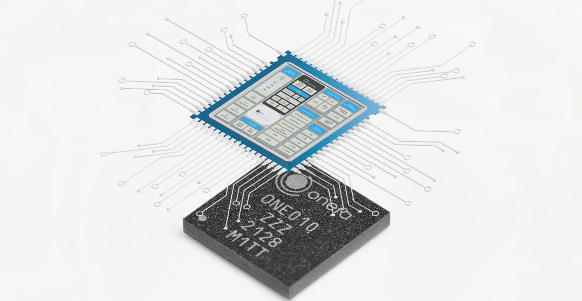
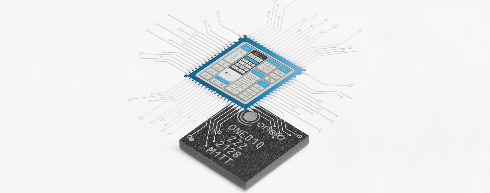
The Sitara AM6442R and Sitara AM6442A SOMs are designed based on Texas Instruments (TI) AM64X processors to offer precise real-time processing and multi-protocol industrial Ethernet solutions. These devices come with 2x Arm Cortex-A53 cores, 4x Cortex-R5F, and one isolated Cortex-M4 core processor. The Arm Cortex-A53 comes with a 1.0GHz clock speed and aims at handling OS and application processing, the Cortex-R5F running at 800MHz is for real-time data computing, the Cortex-M4 core with 400MHz speed is to deal with error monitoring and management. Both SOMs feature an onboard 8GB eMMC storage and a 1GB DDR4 with inline ECC safety protocol. They also feature 2x Gigabit industrial subsystems (PRU-CSSG) for industrial Ethernet solutions, Gen 2.0 PCle, USB 3.0, SPI, I2C, CAN, ADC, PWM, GPIOs, JTAG, Hirose DF40 connectors, and M2M communication support. But, while the Sitara AM6442A has no UART, the Sitara AM6442R has up to 9 UART for handling serial communication. The duo SOM takes in 5V as supply voltage and 3.3V as I/O voltage.

Sitara AM6442R and AM6442A SOM

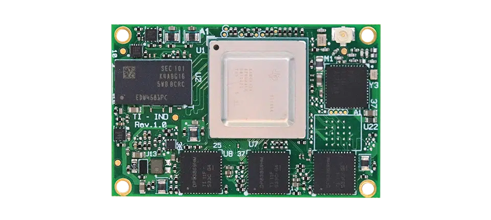
Highlights and Specifications of Sitara AM6442R and AM6442A SOM:

  • CPU: Texas Instruments Sitara AM6442  processor with 2x Cortex A53 cores @ 1.0 GHz, 4x Cortex R5F cores @ 800 MHz, 1x      isolated Cortex M4 core @ 400 MHz
  • Main Voltage: 5V
  • I/O voltage: 3.3V
  • System Memory: 1GB DDR4 with inline ECC
  • Storage:
    • 8GB eMMC
    • Optional QSPI flash (AM6442A only)
  • Networking:
    • AM6442R
    • 1x 10/100/1000 Mbps (PRU ICSSG, Supporting: TSN, EtherCAT, PROFINET, Ethernet/IP)
    • Optional WiFi/Bt (WiLink)
  • AM6442A
    • 1x 10/100/1000 Mbps
    • 2x 10/100/1000 Mbps (PRU ICSSG, Supporting: TSN, EtherCAT, PROFINET, Ethernet/IP)
    • Optional TI CC1312 SimpleLink sub 1GHz wireless MCU
  • Hirose DF40 connectors (x3):
  • External Storage – NOR Flash, 2x SD/MMC, PCIe SSD
  • Networking – Up to 3x Gigabit Ethernet
  • USB: USB 3.0 (x1)
  • PCIe: 1x PCIe (Gen 2.0)
  • I/Os
    • 4x I2C, 1x SPI, GPIO, PWM, 2x CAN
    • Up to 9x UART (AM6442R only)
  • Debugging: JTAG

In addition, the Sitara AM6442X SOM supports Linux OS and is suitable for the development of industrial solutions like factory automation, gateways, industrial robots, and machinery, etc. Public source code on the SOM is available on the Company’s GitHub repository. You will find assistance on how to start using the SOM and use reference designs on SolidRun’s Developer Center.

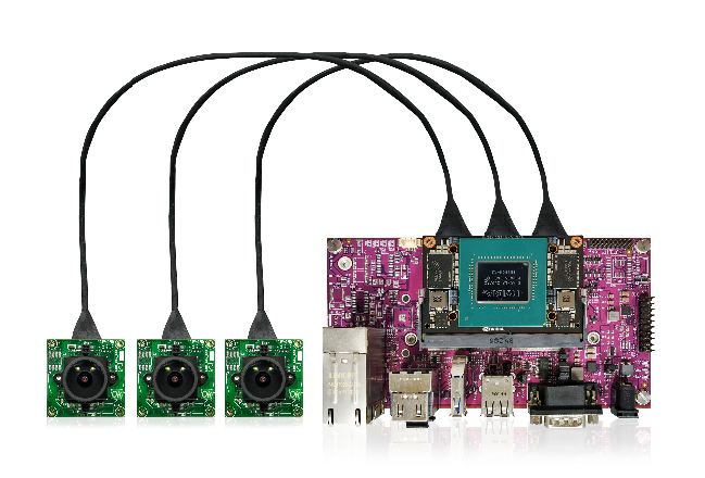
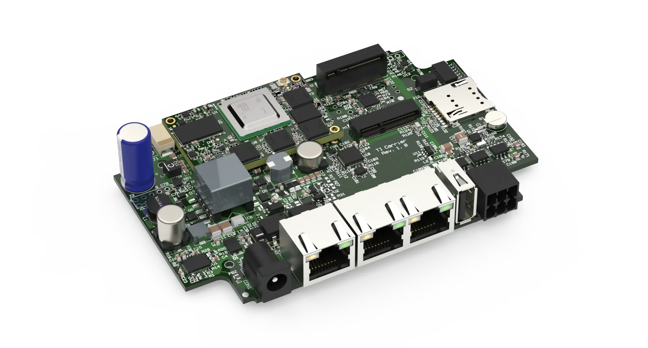
For easy development and prototyping with the AM6442x SOMs, SolidRun offers two SBCs as carrier boards, the HummingBoard-T AM64X Base and the HummingBoard-T AM64X Pro carrier boards to support the AM64X SOMs. The carrier boards feature 1GB DDR4, 8GB eMMC, GPIO header, USB 3.0 I/O, CAN-FD I/O, and RS485/RS232 I/O. All public source code and documentation on the boards point to SolidRun’s GitHub repository and Developer Center.

Carrier board to support the AM64X SOMs

Highlights and Specifications of HummingBoard-T AM64X Carrier Board:

  • CPU:
    • TI Sitara AM6424 Arm Cortex A53 Dual core @ 1GHz + 4 x Cortex R5 @ 800MHz + 1 x Cortex M4 @ 400MHz, with 1GB RAM, 8GB flash
  • Power Supply: 9V-36V (DC)
  • Networking:
  • HummingBoard-T AM64x Base:
    • 1x 10/100/1000 Mbps (PRU ICSSG, Supporting: TSN, EtherCAT, PROFINET, Ethernet/IP)
    • Optional WiFi/Bt
    • 1x Optional Cat 4 LTE with SIM Holder
  • HummingBoard-T AM64x Pro:
    • 1x 10/100/1000 Mbps
    • 2x 10/100/1000 Mbps (PRU ICSSG, Supporting: TSN, EtherCAT, PROFINET, Ethernet/IP)
    • 1x Optional Cat 4 LTE with SIM Holder
    • 1x CC1312 SimpleLink 1 GHz wireless MCU (on-module optional)
  • USB: USB 3.0 interface (x1)
  • Serial I/Os: 2x CAN-FD, 2x RS485/RS232
  • Expansion: M.2 socket and GPIO header
  • Debugging: Internal console port
  • Misc:
    • Indication LEDs, user pushbuttons, RTC with battery backup, Optional battery charger, Optional 802.3af POE PD (HummingBoard-T AM64x Pro only)

For more information and purchase, you should visit the AM64X products page and the HummingBoard-T AM64X Base and Pro page. The Products pages have other information like block diagrams, datasheets, and more.

Phi Mainboard 5LC: ESP-32 Based Open Source 3D Printer Controller

Around a decade ago, 3D printers were bulky, expensive machines only used by industries and not available for a large group of people except professionals. 3D printing technology has come a long way since then. But with the open-source movement, 3D printers are now affordable for makers, designers, engineers, hobbyists, and even students. With 3D printers, anyone now can craft their personalized designs. It’s a perfect gadget for a maker or a 3D printing enthusiast. Nowadays, some affordable 3D printers can provide printing quality that looks like professional 3D printing. As a result, 3D printers are now more popular than ever.

Well, it’s fairly easy to start your way into additive manufacturing. But the first thing you will need, besides a good 3D printer, is a 3D printer controller. The controller board is responsible for all the logic behind 3D printing. It takes care of things such as parsing G-code files, regulating temperature, and most importantly, controlling FDM (Fused Deposition Modeling) and stepper motors. Nowadays, 3D printing hardware comes with advanced features like 1/256 micro-stepping, UART Mode, and Wi-Fi, among others.

Likha Labs recently announced their open-source ESP32 based 3D printer controller, which comes with built-in Wi-Fi and Ethernet. On their CrowdSupply page, they described it as a 3D printer controller with a focus on network connectivity. Their controller is called Phi Mainboard 5LC, and it provides a web interface that one can use to interact with the 3D printer over a local network. Therefore, you will no longer need a single-board computer like a Raspberry Pi. The web interface allows uploading G-code files, configuration settings, starting jobs, controlling the device, and monitoring printing. Overall, this hardware saves money and simplifies your setup.

It is built around the ESP32-S3-WROOM module and a SAM E51 microcontroller. The ESP32 handles networking, data storage, USB communication, and displays. And the microcontroller takes care of all motion and real-time controls in a 3D printer. This ensures that controlling the printer and networking happens parallelly, and one process doesn’t bog down the other.

The hardware supports a wide range of displays, stepper drivers, and other hardware peripherals like filament monitors, thermocouples, accelerometers, etc. Adding to its flexibility, Phi can also be used to drive other digital fabrication equipment, such as CNC machines.

The technical specifications of the controller hardware are as follows:

Physical

  • 123 x 100 mm, M4 mounting holes
  • 4 layers with 2 oz. outer copper layers (for better heat dissipation)

Processors

  • Espressif ESP32-S3-WROOM-1-N8
    • 512 KB SRAM
    • 8 MB SPI flash
    • Dual-core 240 MHz Xtensa LX7
  • Microchip ATSAME51N19A
    • 192 KB SRAM
    • 512 KB flash
    • 120 MHz Cortex-M4F

Interfaces

  • Micro SD
    • SD v3.0 and v3.01, SDIO v3.0, CE-ATA v1.1, MMC v4.41
  • Micro USB
    • USB 2.0 full-speed (up to 12 Mbit/s)

Networking & Connectivity

  • Bluetooth 5 LE
  • 802.11b/g/n 2.4 GHz Wi-Fi
  • 10/100 Base-T Ethernet

Power

  • Input voltage (VIN) range 11 V – 25 V
  • Input connector rated up to 25 A
  • On-board regulators
    • 1x 12 V, 3 A
    • 2x 5 V, 3 A
    • 2x 3.3 V, 1 A

Machine Features

  • 5x TMC2209 stepper drivers
    • 2 A RMS
    • Up to x256 microstepping
    • StealthChop2 (for silent operation)
    • StallGuard2 (for stall detection and sensorless homing)
  • 2x extruder heaters (each up to 5 A)
  • 1x bed heater (up to 15 A)
  • 3x thermistors or PT1000s
  • 4x PWM fans, 1x always-on
    • 2x with tach input
    • Selectable between VIN and 12 V in two banks
  • 1x VFD/Laser/Servo (5 V output)
  • 7x GPIO ports (for end-stops, filament monitors, Z-probes, SSRs, etc.)
    • 30 V tolerant input
    • 3.3 V output

Specialty Ports

  • EXP1, EXP2
  • PanelDue 4-pin & 10-pin
  • NeoPixel
  • CAN-FD expansion
  • Stepper expansion
  • Thermocouple or PT100 expansion

Overall, Phi is an amazing tool for makers, hobbyists, and even professionals who like to experiment with 3D printing and enjoy customization. Phi is open-source and the schematic, PCB layout, GCC, and CMake for firmware are freely available on their GitHub page.

Phi Mainboard 5LC CrowdSupply Page: https://www.crowdsupply.com/likhalabs/phi-mainboard-5lc

NXP IW612 Tri-Radio Device Supporting Wi-Fi 6, Bluetooth 5.2 and ZigBee

CES has always been interesting for tech enthusiasts looking for some next-generation high technologically advanced products. In regards to IoT and wireless communication, NXP showcased IW612 as the industry’s first secure tri-radio device which can now support Wi-Fi 6, Bluetooth 5.2, and 802.15.4 technical standards. NXP had a similar single-chip device by the name of IW416 which supported Wi-Fi 4 and Bluetooth 5.2. Taking the bar towards innovation, IW612 features an efficient power management system that comes with deep-sleep and low-power modes.

Focusing more on wireless connectivity, the single-chip aims to work in industrial applications like smart homes and smart appliances other than industrial automation and gateways. As published in the internal block diagram, the manufacturer decided to integrate dedicated and independent CPUs for Wi-Fi 6 and Bluetooth wireless communication protocols. There are single and dual antenna configurations available in the production. This has enabled real-time and independent protocol processing. An external host processor can be interfaced through SDIO 3.0 for Wi-Fi while UART for Bluetooth and SPI for 802.15.4.

NXP IW612 Internal Block Diagram

As mentioned earlier, the chip features a full Wi-Fi subsystem which is powered by the NXP’s 802.11ax technology that aims to bring better network efficiency while reducing the latency and improving the range. Wi-Fi interestingly features 802.11az accurate range technology which was part of IEEE802.11mc standard release. This takes advantage of several improvements done to the 802.11ax Wi-Fi standard.

Bluetooth enables hands-free and advanced audio distribution production for audio streaming. The low-energy configuration of Bluetooth supports 2 Mbit/s data speed for medium-to-long rate communication. Furthermore, IW612 also integrates the support for Thread and Zigbee mesh network in 2.4 GHz band frequency. However, it comes at the cost of a shared transmitter and antenna pin with the Bluetooth subsystem.

Through the massive integration of several wireless communication subsystems, the single-chip is claimed to have a very low system cost through a minimum external BOM. For more details on the NXP IW612 tri-radio device, visit the product page.

Low-Cost DC Motor Direction Controller with Fast Brake using 2 Relays

The project presented here is a low-cost easy to use DC brushed motor direction controller with fast-brake, the project was built using two 12V Relays, 2 x BJT transistors, and 2 x tactile switches. The two LEDs are provided to display the motor direction, 2 tactile switch controls the direction of the motor.

Operation

Connect 12V DC power supply to connector CN1, connect 12V DC brushed Motor to CN2. The motor will run in any direction by pressing any of the switches, other switch will rotate the motor in another direction. When the user leaves the switch fast brake apply as both terminals of the motor are short when both relays are in an OFF state.

Features

  • Operating Supply 12V to 14V DC
  • Motor Load Up to 10A
  • Fast Brake while changing the direction
  • 2 x LED to display the direction of the motor
  • 2 x Tactile Switches to Control the Direction
  • PCB Dimensions 52.55 x 43.18 mm

Schematic

Parts List

NO.QNTY.REF.DESC.MANUFACTURERSUPPLIER PART NO
11CN12 PIN SCREW TERMINAL PITCH 5.08MMPHOENIXDIGIKEY277-1247-ND
21CN22 PIN SCREW TERMINAL PITCH 5.08MMPHOENIXDIGIKEY277-1247-ND
31C1470uF/25VNICHICONDIGIKEY493-1553-ND
41C20.1uF/50V SIZE 0805MURATA/YAGEODIGIKEY
52D1,D3SM4007 SMD DIODE DIGIKEYS1MBDITR-ND
62D2,D4LED SMD SIZE 0805OSRAMDIGIKEY475-1278-1-ND
72Q1,Q2BC847 NEXPERIADIGIKEY1727-2924-2-ND
82RE1,RE212V RELAYTE CONNECTIVITYDIGIKEYPB2029-ND
92R1,R41K 5% SMD SIZE 0805MURATA/YAGEODIGIKEY
102R2,R52K2 5% SMD SIZE 0805MURATA/YAGEODIGIKEY
112R3,R610K 5% SMD SIZE 0805MURATA/YAGEODIGIKEY
121SW1TACTILE SWITCHNKK SWITCHDIGIKEYHP0215AFKP2-ND
131SW2TACTLIE SWITCHNKK SWITCHDIGIKEYHP0215AFKP2-ND

Connections

Gerber View

Photos

Video

BC847 Datasheet

Shenzhen Xunlong’s Orange Pi 3 LTS Single-Board Computer For $35


Chinese manufacturer, Shenzhen Xunlong has launched yet another open-source single-board computer featuring the Allwinner H6 system-on-chip: Orange Pi 3 LTS. We have witnessed the new Orange Pi hitting the market every time around this time of the year, just like the Orange Pi R1 Plus last year. Orange Pi 3 LTS comes with the aim of providing a platform to the maker community who can take advantage of the newly integrated SoC and create interesting projects that target a wide range of applications.

At the heart of Orange Pi 3 LTS is the Allwinner H6 system-on-chip which comes with a Quad-core 64-bit high-performance Cortex-A53 processor clocked up to 1.8GHz frequency. The hardware design integrates the AW859A Chip that provides Wi-Fi (support IEEE 802.11 a/b/g/n/ac) and Bluetooth (support BT5.0) wireless connectivity. Interestingly, the board has 2GB LPDDR3 SRAM which might restrict a few complex applications. However, it is important to note that Allwinner H6 SoC was primarily designed as a high-performance 4K HDR set-up box chip indicating that the majority of video processing applications are expected to work smoothly.

Specifications of Orange Pi 3 LTS:

  • CPU: Allwinner H6 with Quad-core Cortex-A53 processor @ 1.8GHz
  • GPU: Mali T720 high-performance, multi-core GPU
  • Memory: 2GB LPDDR3 (shared with GPU)
  • Storage: 8GB eMMC flash and expandable through Micro SD card slot
  • Wireless connectivity: IEEE 802.11a/b/g/n/ac and Bluetooth 5.0
  • USB: 1x USB 3.0 host, 2x USB 2.0 host
  • Video output: HDMI 2.0 and TV CVBS output
  • Audio output: HDMI output, 3.5mm audio port
  • Power: 5V via Type-C
  • Peripherals: 1x I2C, 1x SPI, 1x UART and multiple GPIOs
  • Operating systems: Android 9.0, Ubuntu, Debian
  • Dimension: 56x85mm
  • Weight: 45g

Not to forget, the powerful SoC is equipped with a Mali T720 GPU that supports OpenGL ES, Microsoft DirectX, and also adaptive scalable texture compression. Video and audio output can be taken through the onboard HDMI ports. To make it easier, the board can be powered via Type-C cable other than multiple pin connectors. Most importantly, the hardware supports Android 9.0, Ubuntu and Debian operating systems for you to build your own wireless server.

For more details on Orange Pi 3 LTS, visit the product page. You can consider purchasing this $35 single-board computer on Aliexpress.

Open Source CaribouLite SDR Raspberry Pi HAT for $119

Raspberry Pi ecosystem has witnessed an open-source software-defined radio HAT after a very long time. All-long CaribouLite is looking to crowdfunding for mass production and to get a response from the hacker community. After a series of changes since the first draft version seen on CrowdSupply, [David] finally announced the launch of the new product that enabled up to 6GHz of adjustable bandwidth. This easily mountable Raspberry Pi HAT utilized all 40-pin of the single-board computers, being one of the few HATs with 40-pin headers.

Unlike SDR platforms, CaribouLite is an easy-to-use dual-channel with a software-defined radio-focused FPGA development framework. The aim of the hardware comes to transform the single-board computer into a dual-channel radio with a transmitter and receiver that operates with a tunable frequency along the spectrum of up to 6 GHz. Due to its open-source nature, hackers can play around with the software of the SDR HAT and bring new upgrades to the community. Designed with the purpose of aid makers, hackers, educators, and researchers at a very affordable price while maintaining high quality, making it complement the current SDR ecosystem.

Specifications of CaribouLite SDR HAT:

  • Radiofrequency chip: AT86RF215
  • FPGA: ICE40LP 1.38 kLE
  • Tuning frequency spectrum: Channel 1- 30MHz to 6GHz, Channel 2- Sub-1GHz
  • Max sampling rate: 4 MSPS
  • Max RF bandwidth: 2.5MHz
  • Channels: 2
  • Processor: BCM283x (x1/4) and BCM2711 (x4)
  • Bus/interface: Secondary memory interface
  • Operating system: Linux (dependent on the RPi SBC)
  • Dimensions: 65×30 mm

CaribouLite has two versions, one with all the features and the other comes as an ISM version. The latter operates with a tuning range of 2.4 to 2.4835GHz for channel 1 which is much less than the full version. The hardware supports standard IEEE-802.15.4 PHY built-in cores implemented within the AT86RF215-ZU modem. With these radio channels, the user can implement hardcore basebands and communication points such as Zigbee and Thread. When it comes to powering CaribouLite, it draws all the power from the Raspberry Pi’s 5V rail through 40-pin headers.

Project files are hosted on Github.com: https://github.com/cariboulabs/cariboulite

If you are interested in supporting the crowdfunding campaign on Crowdsupply, proceed to the product page with a minimum $69 for the ISM version and $119 for the full version.

TinyOLEDdemo – I²C OLED on an ATtiny10, ATtiny13A or ATtiny202

This is just a little demo on how to use an I²C OLED with the limited capabilities of an ATtiny10, ATtiny13A or ATtiny202 from Stefan Wagner @ github.com

Connect the OLED module to the ATtiny13A as shown below. The connections for the ATtiny10 are similar. For the ATtiny202 SDA must be connected to PA1 (pin 4) and SCL (or SCK) to PA2 (pin 5).

Since the I²C implementation for ATtiny10/13A is software-based, you can of course use any other I/O pins instead. Just change the relevant definitions in the code. The implementation for the ATtiny202 uses hardware TWI, so the pins provided for this must be used.

more details: https://github.com/wagiminator/ATtiny13-TinyOLEDdemo

e-con Systems™ launches 18 MP MIPI camera module for the NVIDIA Jetson Xavier™ NX platform

1/2.3-inch AR1820 sensor | 18 MP MIPI CSI 2 | 4 levels of zoom | NVIDIA Jetson Xavier™ NX   

e-con Systems™ launches e-CAM180_CUMI1820_MOD, an 18 MP MIPI camera solution for the NVIDIA Jetson Xavier™ NX platform.

e-CAM180_CUMI1820_MOD is based on the 1/2.3-inch AR1820 sensor from ON Semiconductor. This camera module provides image output at a resolution of 18MP with great details. e-CAM180_CUMI1820_MOD also comes with 4 levels of zoom that allow users to swivel the camera from left to right, tilt it up and down, and zoom in and out of a scene. This MIPI CSI-2 camera module uses the NVIDIA Jetson ISP to produce best-in-class image output in uncompressed YUV format. It has an M12 lens holder which offers customers an opportunity to use the lens of their choice.

Key features of e-CAM180_CUMI1820_MOD

  • 1/2.3-inch AR1820 sensor – Image output at a resolution of 18MP with great details
  • 4 levels of zoom – Allows user to pan, tilt, and zoom in and out of a scene
  • MIPI CSI-2 – Can connect up to three 4-lane MIPI camera modules on Diamond System’s FLOYD carrier board housing NVIDIA Jetson Xavier™ NX.
  • ISP – Uses the NVIDIA Jetson ISP to produce best-in-class image output in uncompressed YUV format.

This multi-camera solution comes ready to be evaluated with the NVIDIA® Jetson Xavier™ NX development kit and Diamond System’s FLOYDNX carrier board with the necessary software. The solution allows customers to connect up to three 4-lane MIPI camera modules on the FLOYD carrier board housing NVIDIA Jetson Xavier™ NX. This MIPI camera module can stream 18MP at 13 fps with 4-lane configuration.

e-CAM180_CUMI1820_MOD is ideal for smart surveillance systems and digital microscopes owing to its 18 MP resolution, multi-level zoom, and NVIDIA Jetson platform support.

For more information on the camera module and evaluation kit please check the following links

Video

Availability

Customers interested in evaluating e-CAM180_CUMI1820_MOD – an 18 MP MIPI camera solution for the NVIDIA Jetson Xavier™ NX platform – can purchase the product from e-con Systems™’ online store.

Biomedical ‘lab-on-chip’ for wearable health

Wearable biomedical product developer Onera Health has introduced an ultra-low-power biosignal sensor hub for wearable health.

The Onera Biomedical-Lab-on-Chip sensor system-on-chip acquires and processes multiple biosignals and is designed for a broad range of wearable health applications and devices. The devices, says the company, offer many solutions and opportunities for innovation in the medical, wellness and fitness space.

“Our highly integrated and comprehensive biosignal sensor hub is a unique solution that promises to revolutionize this competitive field,” says Ruben de Francisco, Founder and CEO of Onera. “It combines clinical-grade physiological measurements and analysis with ultra-low-power consumption, enabling the development of miniaturized and high-quality wearable devices. Launching this powerful chip as a stand-alone product within our portfolio, not just as part of our innovative Onera diagnostic and monitoring solutions, is yet another exciting step for our company.”

The Onera Biomedical-Lab-on-Chip is a multi-channel sensor readout system with integrated data processing, power management, and interfacing features. It offers a wide range of on-chip biomedical sensor readouts, including 10 readouts for ExG, covering EEG, ECG, EMG, and EOG, two bioimpedance readouts, and two readouts for photoplethysmography.

The data can be processed by on-chip digital filters and accelerators, supported by an ARM Cortex M4F processor. The chip features several standard wired interfaces such as UART, SPI, I2C, and I2S.

The chip fully operates on a single power source which can be anything between 0.8V and 3.6V, since power management is also integrated on-chip. In addition, a large amount of SRAM and embedded FLASH is available, supporting the large number of data streams with accurate data-synchronization as an essential feature.

To support the development and transition to commercialization of its products, the company says it has recently ramped-up hiring, including adding to its leadership team.

more information: Onera Health

BLDC Motor and DC Brushed Motor Driver

This BLDC motor driver board is equipped with a smart IFX007T half-bridge. The BLDC motor control project is capable to drive one BLDC motor. Alternatively, it can be used to drive one or two bi-directional DC motors (H-Bridge configuration, cascaded to support the second motor) or up to three uni-directional DC motors (half-bridge configuration). The implemented integrated IFX007T half-bridges can be controlled by a PWM via the IN Pin. Interfacing to a microcontroller or Arduino is easy by the integrated driver IC which features logic level inputs, diagnosis with current sense, slew rate adjustment, and dead time generation, etc. The three IFX007T half-bridges are also fully protected against over-temperature, under-voltage, overcurrent, and short circuit events. The project is capable of high-frequency PWM e.g., 30Khz. All inputs are logic level, current sense outputs are for diagnosis purposes, and slew rates are adjustable using R7, R8, R9. This is able to be used for fast and inexpensive prototyping of (BL)DC motor control, easy testing of half-and full-bridge motor control Status flag diagnosis with current sense capability, Over-temperature shut down with latch behavior and under-voltage shut down. It is advisable to use forced cool air to control the temperature of the IFX007 chip.

BLDC Motor and DC Brushed Motor Driver – [Link]

TOP PCB Companies