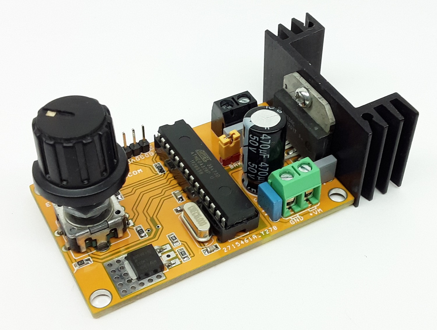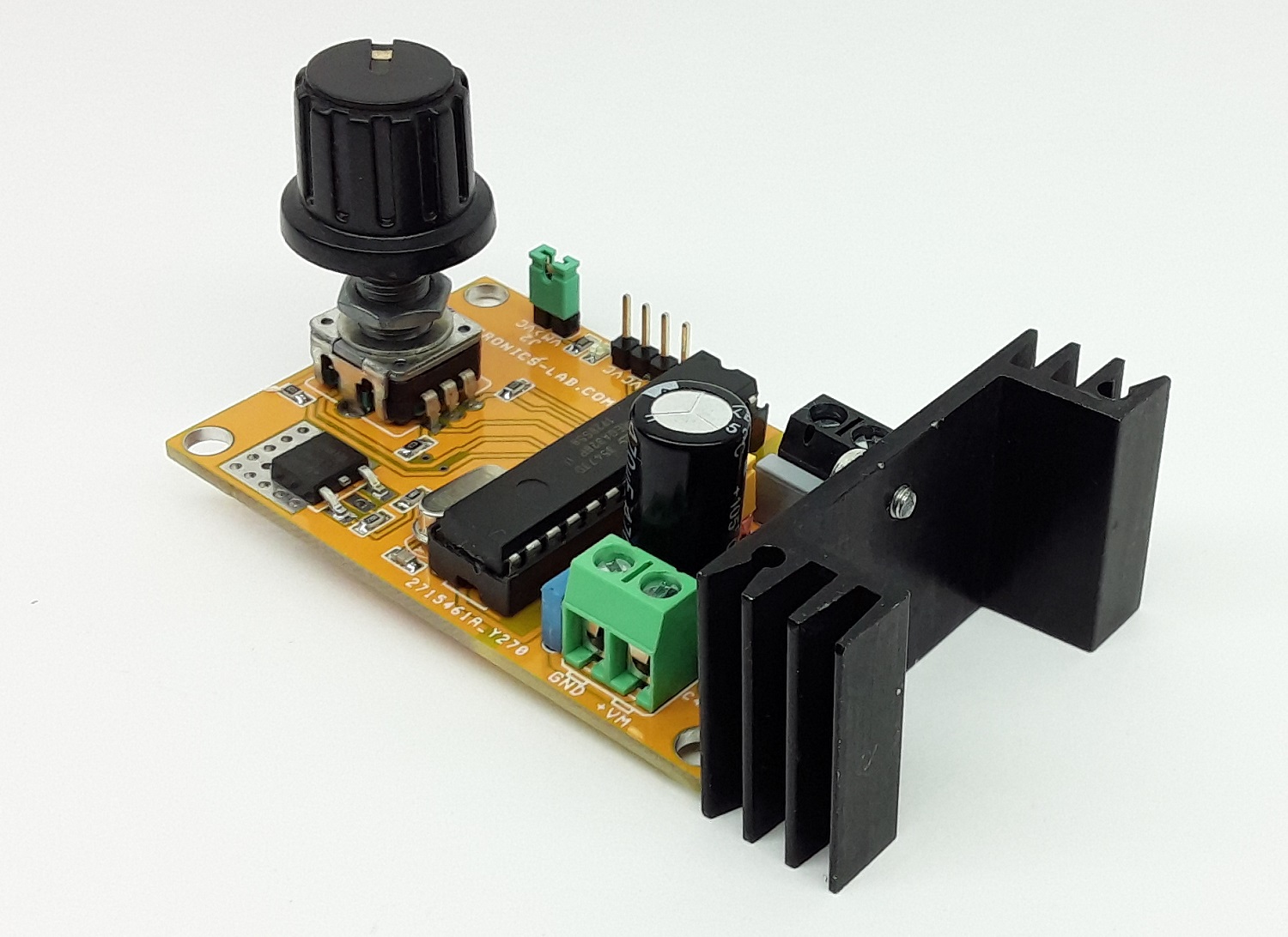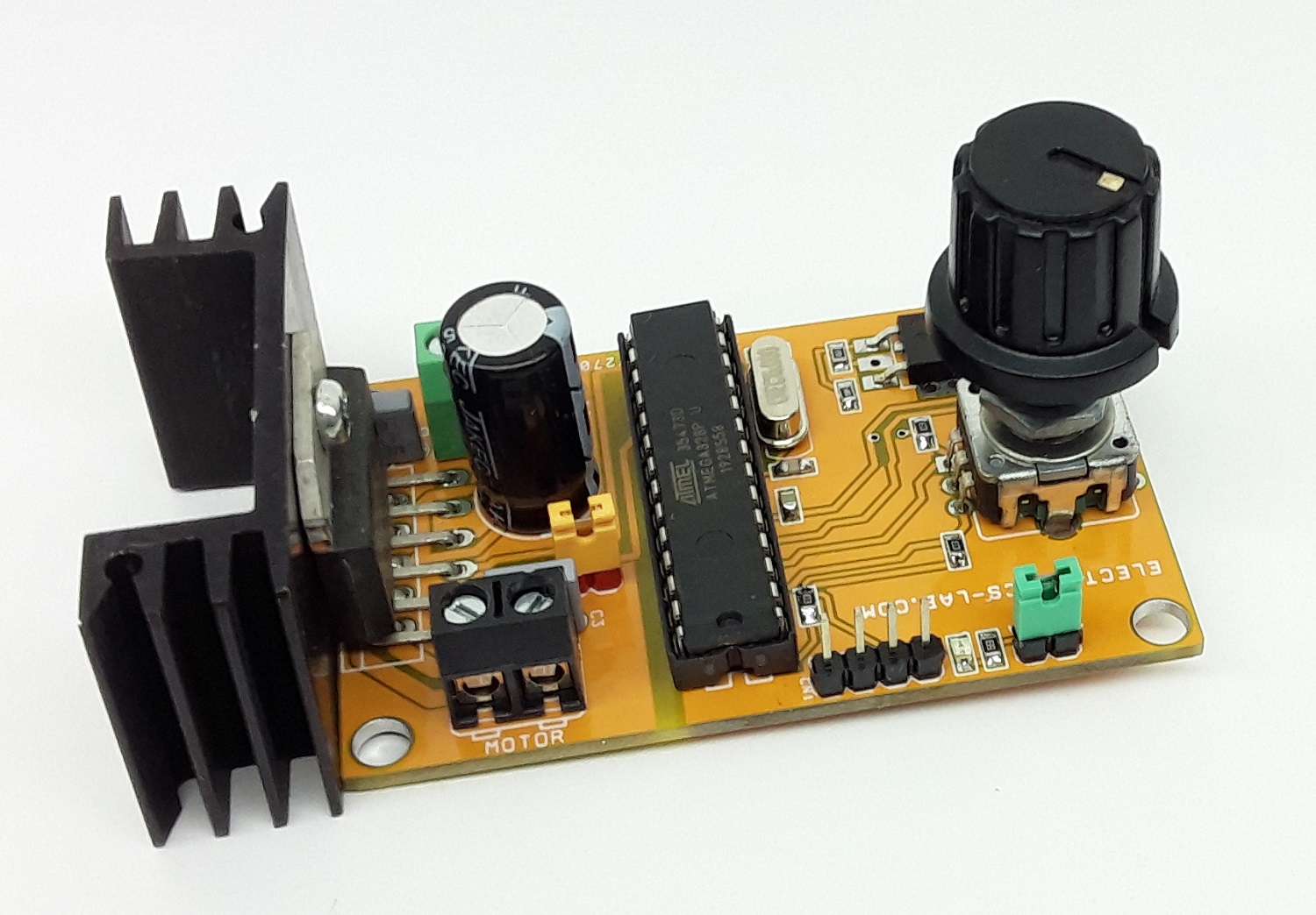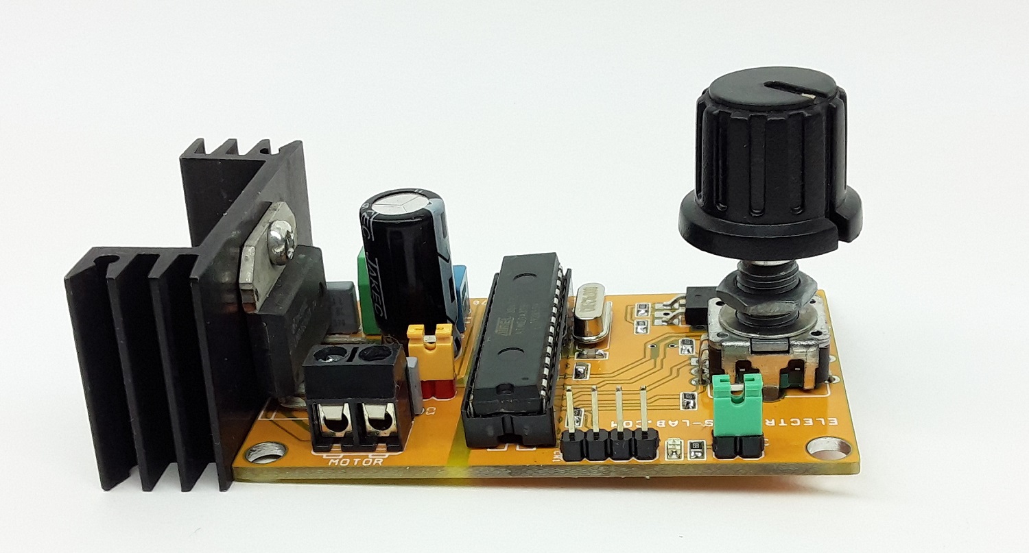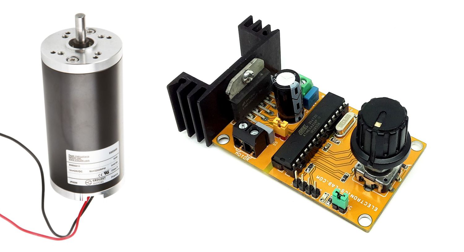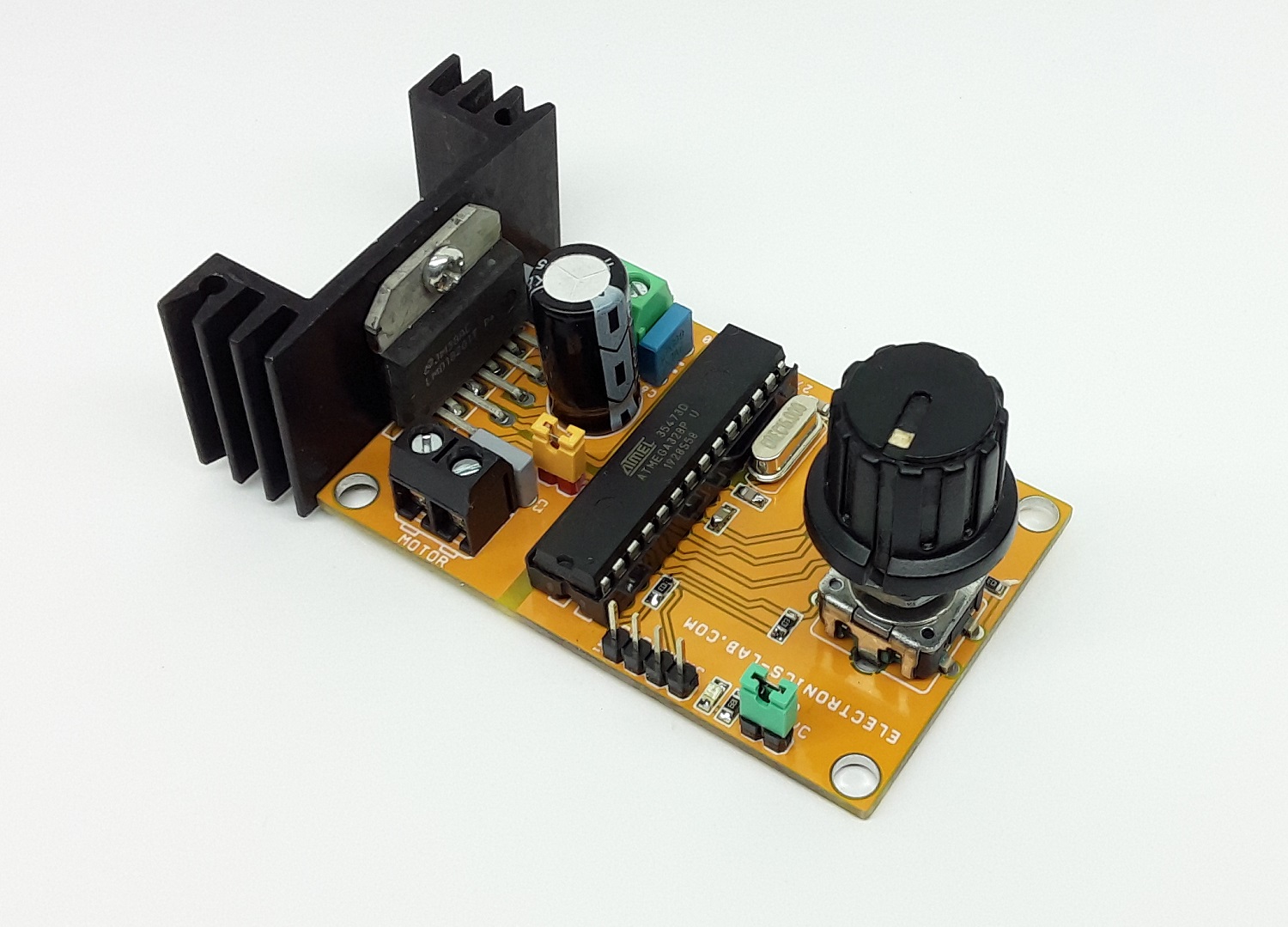
This DC Motor controller provides direction and speed control of brushed DC Motor using Rotary Encoder. This is Arduino compatible hardware that consists of LMD18201 DC motor driver chip, Atmega328 microcontroller, Rotary Encoder, L317 regulator, and other components. Hardware offers easy control of brushed DC motor up to 3A with speed, direction, and brake control. The encoder includes a tactile switch, which can be used to control the ON/OFF or Direction of the motor and the encoder helps to set the speed.
Learn more about Rotary Encoder
- https://www.seeedstudio.com/blog/2020/01/19/rotary-encoders-how-it-works-how-to-use-with-arduino/
- https://playground.arduino.cc/Main/RotaryEncoders/
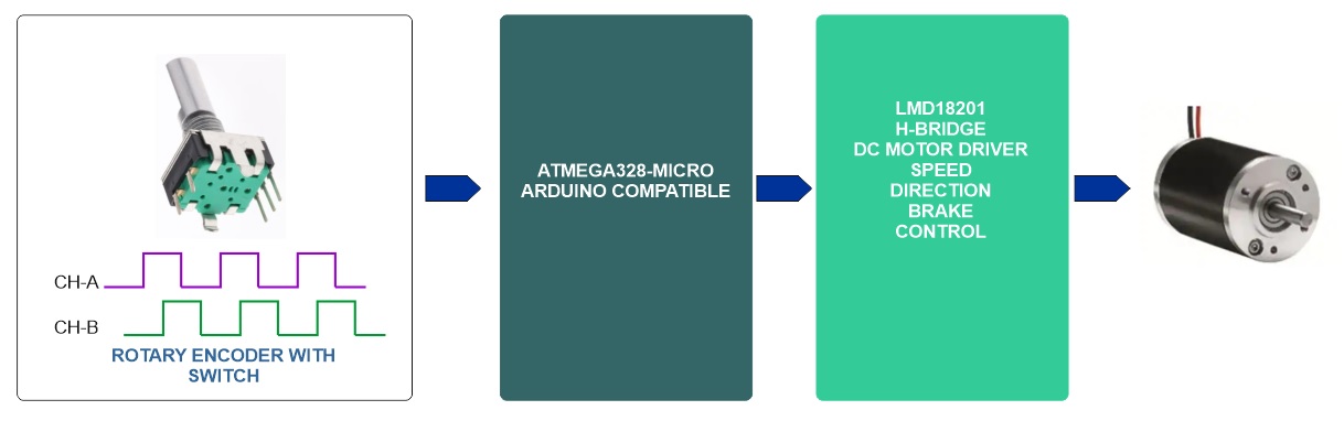
A rotary encoder is a type of position sensor which is used for determining the angular position of a rotating shaft. It generates two pulses, according to the rotational movement, these two pulses determine the direction of the shaft and angular position, this encoder is also included with a mechanical switch. Switch and encoder help to control the DC motor speed and direction.
The project can be described in 3 parts, Atmega328 Microcontroller, LMD18201 DC Motor H-bridge, and Rotary Encoder. This board can control DC motor up to 48V DC and continued current up to 3A, peak current 6A.
Arduino Code
It is Arduino-compatible hardware and a new Atmega328 chip requires bootloader programming and Arduino code upload. Follow the link below for more info on programming and boot-loader burning.
Credits: This is modified Arduino Code, Original Author of the code https://www.brainy-bits.com
https://www.arduino.cc/en/Tutorial/BuiltInExamples/ArduinoToBreadboard
Arduino Example code provided to test the board, with this code user will be able to test the hardware. Code may be modified as per requirement.
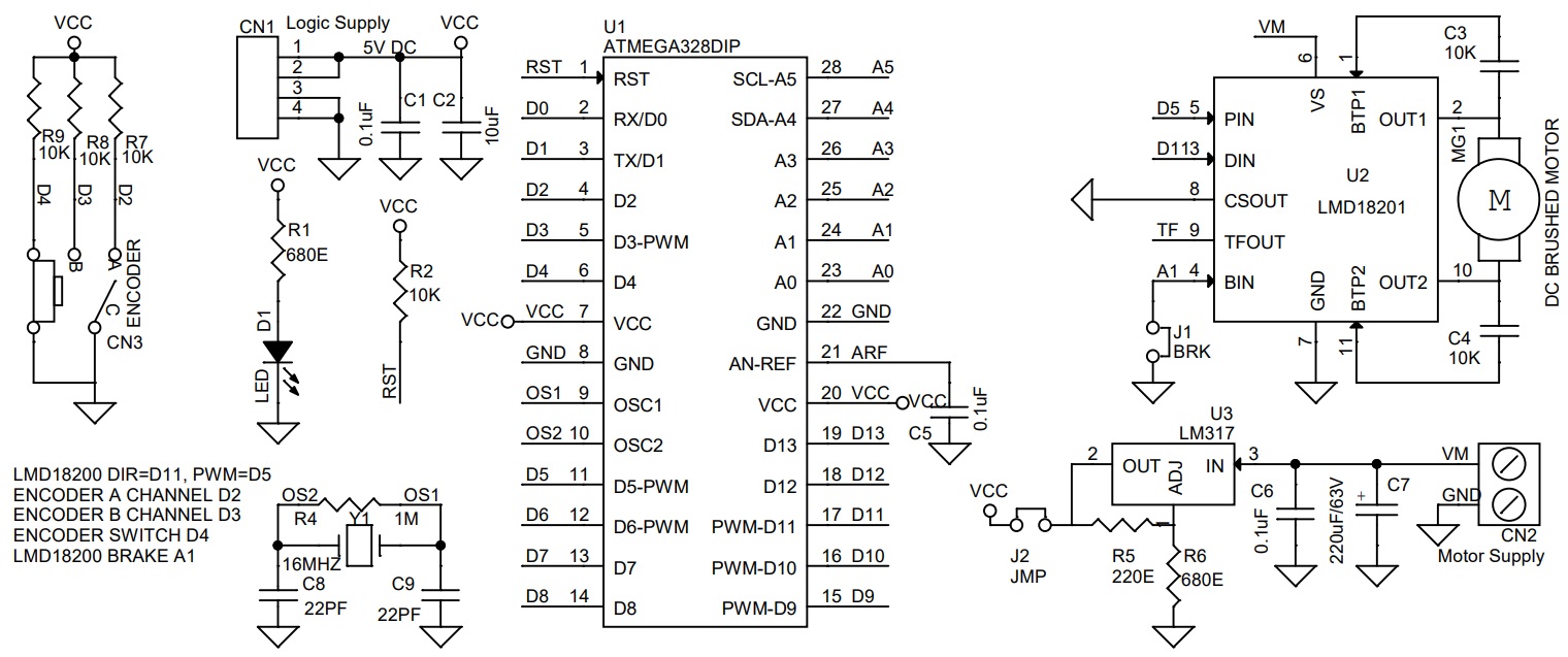
Arduino Pins Vs LMD18201 Motor Driver Pins
- Arduino Digital D5>>PWM Pin LMD18201,
- Arduino Digital Pin D11 >> Direction Pin LMD18201,
- Arduino Analog Pin A1 >> Brake Pin LMD18201 (Close the jumper J1 for Normal Operations If Brake Function Not Required)
- Arduino Digital Pin D2 >> Encoder Channel A- Pin Pulled Up using R7-10K
- Arduino Digital Pin D3>> Encoder Channel B- Pin Pulled Up using R8-10K
- Arduino Digital Pin D4>> Tactile Switch of Encoder – Pulled Up using R9-10K
Features
- Operating Power-Supply 12V to 24V DC (For Motor 25V to 48V Power Refer the Note)
- Motor Load 3Amps
- D1 Power LED
- Encoder with Switch = Motor Direction CW/CCW and Speed Control
- PWM Duty Cycle Adjustable 0 to 100% (Frequency 975Hz)
- Onboard L317 Regulator provides 5V to Atmega328
- PCB Dimensions 66.83 x 41.91 mm
Power Supply
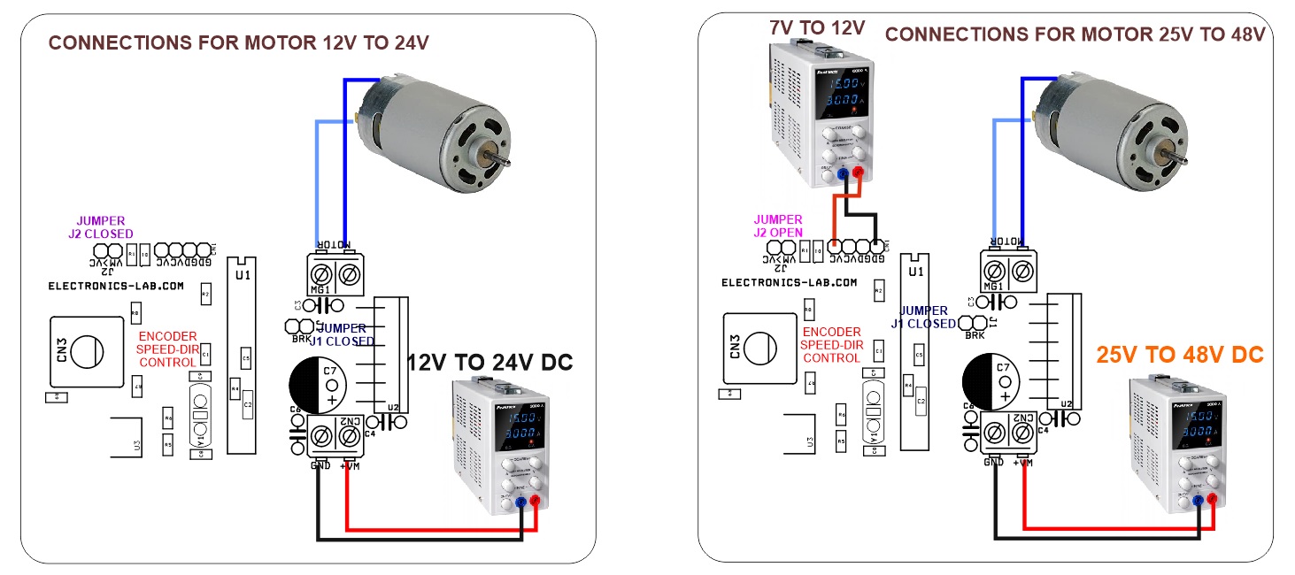
Motor 12 to 24V can work with a single supply, apply 12 to 24V at CN2, close Jumper J2. To drive a higher voltage motor, the circuit requires 2 separate power supplies, for logic and motor, in this case, open the jumper J2, use CN2 to apply motor supply 25V to 48V, and CN1 7V to 24V logic supply.
Heat-sink
Large Size heatsink with fan recommended on LMD18201 chip if the motor is running on full power 3Amps.
LMD18201
The LMD18201 is a 3A H-Bridge designed for motion control applications. The device is built using a multi-technology process that combines bipolar and CMOS control circuitry with DMOS power devices on the same monolithic structure. The H-Bridge configuration is ideal for driving DC and stepper motors. The LMD18201 accommodates peak output currents up to 6A. Current sensing can be achieved via a small sense resistor connected in series with the power ground lead. For current sensing without disturbing the path of current to the load, the LMD18200 is recommended.
Schematic
Parts List
| NO. | QNTY. | REF. | DESC | MANUFACTURER | SUPPLIER | PART NO |
|---|---|---|---|---|---|---|
| 1 | 1 | CN1 | 4 PIN MALE HEADER PITCH 2.54MM | WURTH | DIGIKEY | 732-5317-ND |
| 2 | 1 | CN2 | 2 PIN SCREW TERMINAL PITCH 5.08MM | PHOENIX | DIGIKEY | 277-1247-ND |
| 3 | 2 | C5,C6 | 0.1uF/50V SMD SIZE 0805 | YAGEO/MURATA | DIGIKEY | |
| 4 | 1 | C2 | 10uF/6.3V SMD SIZE 1206 | YAGEO/MURATA | DIGIKEY | |
| 5 | 6 | R2,R7,R8,R9 | 10K 5% SMD SIZE 0805 | YAGEO/MURATA | DIGIKEY | |
| 6 | 1 | C7 | 470uF/50V OR 63V | NICHICON | DIGIKEY | 493-12789-3-ND |
| 7 | 2 | C8,C9 | 22PF/50V SMD SIZE 0805 | YAGEO/MURATA | DIGIKEY | |
| 8 | 1 | D1 | LED RED SMD SIZE 0805 | LITEON INC | DIGIKEY | 160-1427-1-ND |
| 9 | 2 | J1,J2 | 2 PIN MALE HEADER PITCH 2.54MM | WURTH | DIGIKEY | |
| 10 | 1 | J1,J2 | JUMPER-SHUNT | SULINS | DIGIKEY | S9001-ND |
| 11 | 1 | MG1 | 2 PIN SCREW TERMINAL PITCH 5.08MM | PHOENIX | DIGIKEY | 277-1247-ND |
| 12 | 2 | R1,R6 | 680E 1% SMD SIZE 0805 | YAGEO/MURATA | DIGIKEY | |
| 13 | 1 | R4 | 1M 5% SMD SIZE 0805 | YAGEO/MURATA | DIGIKEY | |
| 14 | 1 | R5 | 220E 1% SMD SIZE 0805 | YAGEO/MURATA | DIGIKEY | |
| 15 | 1 | CN3/SW1 | ROTARY ENCODER EN11-HSM1BF20 | TT ELECTRONICS | DIGIKEY | 987-1398-ND |
| 16 | 1 | U1 | ATMEGA328DIP | MICROCHIP | DIGIKEY | ATMEGA328-PU-ND |
| 17 | 1 | U2 | LMD18201 | TI | DIGIKEY | LMD18201T/NOPB-ND |
| 18 | 1 | U3 | LM317 | ON SEMI | DIGIKEY | LM317MDTRKGOSCT-ND |
| 19 | 1 | Y1 | 16MHZ | ECS INC | DIGIKEY | X1103-ND |
| 20 | 2 | C3,C4 | 0.01UF/63V | KEMET | DIGIKEY | 399-5437-ND |
| 21 | 1 | C1 | 0.1UF/63V | EPCOS/TDK | DIGIKEY | 495-2479-1-ND |
Function Diagram
Connections
Gerber View
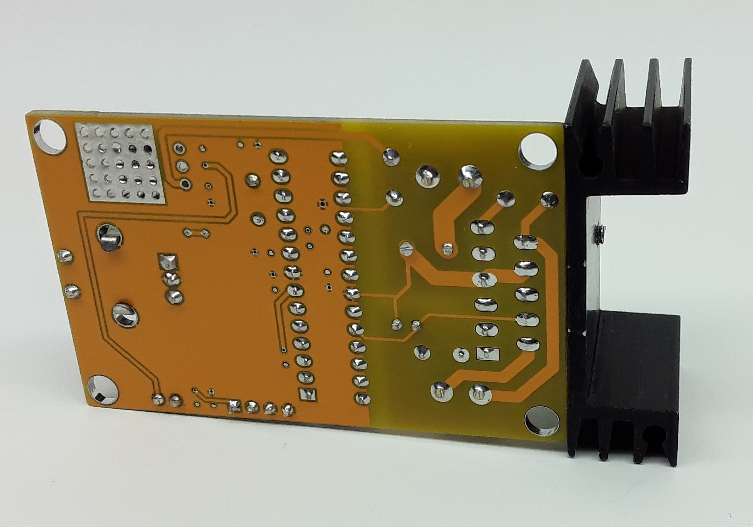
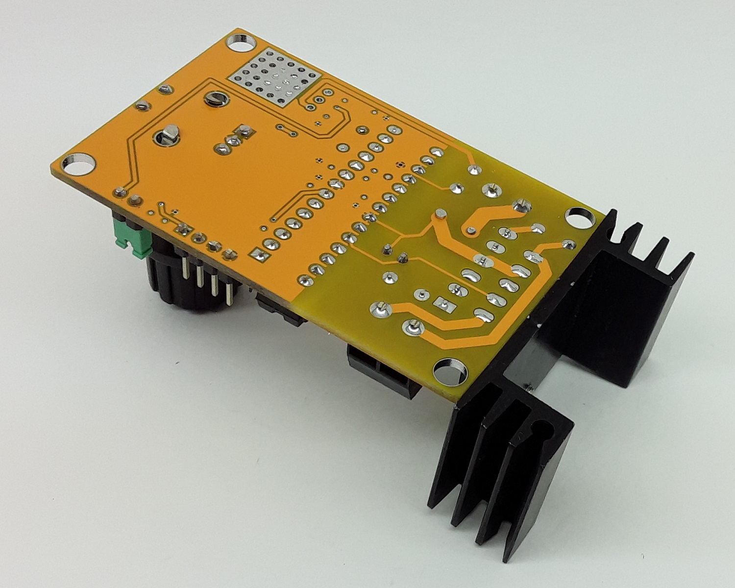
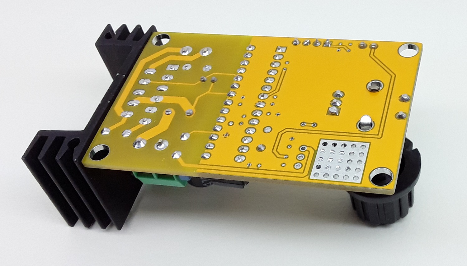
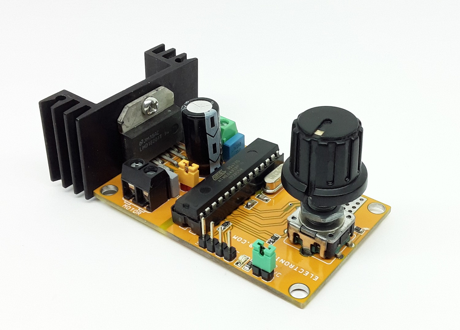
Photos