Amlogic T972 Player board features multiple HDMI inputs – support 4K V-by-One displays and Android 9.0

Amlogic T972 Multimedia Network Player Board

Shenzhen Tomao, one of the leading OEM/ODM manufacturers with over 9 years of experience, has designed an Amlogic T972 multimedia network single-board computer with multiple HDMI inputs and a V-By-One display interface with support for up to 4K resolutions.

Targeted at digital signage applications, the Amlogic T972 SBC is powered by an advanced quad-core Cortex-A55 Amlogic T972 processor. The SoC is a combination of a powerful CPU/GPU subsystem, a best-in-class HDR image processing pipeline, and a secured 8K/4K video CODEC engine with all major peripherals in a cost-effective package. It is designed for worldwide UHD TV applications and so it features a 10/100/1000M Ethernet MAC with RGMII, USB 2.0 high-speed port, SDIO 3.0 controller, eMMC 5.0 controller, SLC NAND controller and multiple SD card controllers, UART, I2C, high-speed SPI PWMs, and a built-in IR blaster. The SoC already happens to power the Xiaomi Mi TV 5 and Mi TV 5 Pro 4k televisions as well as the Developer Board 7+ by Geniatech, you can say it is an equivalent to the Amlogic S905X3 SoC that is built for TV boxes.

The Amlogic T972 network player SBC also features a microSD card slot, 2GB or 4GB DDR4, 16GB eMMC flash expandable to 128GB, HDMI 2.1 receiver ports, up to 4K resolution V-by-One output, one 40-pin LVDS connector, USB 2.0 ports, 2.4G WiFi and Bluetooth (with a dual-band 2.4G/5G WiFi option), one headphone jack, serial expansion ports, mini PCIe slot, sim card slot, backlight header, up to four UART headers, RTC, and many more.

Block Diagram

Specifications of the Amlogic T972 single-board computer Include:

  • CPU: Amlogic T972 (or T962X2) quad-core Arm Cortex-A55 processor @ 1.98 GHz
  • Arm Mali-G31 MP2 GPU with support for OpenGL ES 3.2, Vulkan 1.1, and OpenCL 2.0; Concurrent multi-core processing
  • 2GB or 4GB DDR4 (optional)
  • 16GB eMMC flash (can be expanded to 128GB via SD/USB)
  • 1x MicroSD card slot
  • 40-pin 2.0mm pitch 8-/10-bit LVDS connector up to 1080p resolution
  • V-By-Oneconnector up to 4K resolution
  • TP header, Backlight header
  • 3x HDMI inputs, AV input
  • 3.5mm headphone jack
  • 4-pin header for 10W8Ω stereo speakers, I2S header, PDM header
  • 10/100M Ethernet RJ45 port
  • 2.4 GHz WiFi 4 & Bluetooth (optional dual-band WiFi, Ampak AP6256 as on photo)
  • Optional 4G LTE modem via mPCIe socket + SIM card slot
  • 2x USB Type-A host ports
  • 3x USB interfaces via headers, including one OTG port
  • 1x mini PCIe socket
  • 4x UART headers
  • IR receiver
  • RTC+ battery backup
  • 12V power supply input via DC power jack or 4-pin header
  • 5V header likely output
  • Dimensions: 160 mm x 115 mm
  • Operating System: Android 9.0

Other useful details may be found on the product page.

Pre-Amplifier for MEMS Microphone

This is a low-cost, small-size audio pre-amplifier for MEMS microphone, OPAMP-based circuit amplifies the low-level analog signal coming from MEMS microphone to the desired level required for the next stage which is an audio amplifier, basically microphone level to line level.

Resistor R4 and R7 are used to generate a voltage reference to bias the input common-mode voltage of the op-amp at VCC/2, C7, C8, and R7 help to reduce power supply noise. R5 and C5 allow AC coupling of the microphone signal.  R2 and C2 create a low-pass gain so as not to amplify noise beyond the audio bandwidth. R3 and C6 create a high-pass gain so as not to amplify the DC biasing of the op-amp (including input offset voltage). The cut-off frequency is 59 Hz. D1 is a power LED, this board has a dual option for MEMS microphones. Users may solder onboard microphones or connect external microphones. This board is tested with external Analog MEMS microphone modules from PUI Audio which comes with 3 connections VCC, GND, and output.

Features

  • Supply 3.3V
  • Very Low Noise Output
  • On-Board Power LED
  • Dual Microphone Option (Onboard or External Microphone)
  • The OPAMP gain is set to 32 (Gain = 1+R2/R3)
  • PCB Dimensions 27.78 x 14.29 mm

Schematic

Parts List

NO.QNTY.REF.DESC.MANUFACTURERSUPPLIERPART NO
11CN14 PIN MALE HEADER CONNECTOR PITCH 2.54MMWURTHDIGIKEY732-5317-ND
21CN2AMM-3742-T-EB-RPUI AUDIODIGIKEY668-AMM-3742-T-EB-R-ND
32C1,C51uF/25V SMD SIZE 1206MURATA/YAGEODIGIKEY
41C2560PF/50V SMD SIZE 0805MURATA/YAGEODIGIKEY
51C30.1uF/50V SMD SIZE 0805MURATA/YAGEODIGIKEY
62C4,C810uF/6.3V SMD SIZE 1206MURATA/YAGEODIGIKEY
71C63.3uF/10V SMD SIZE 1206MURATA/YAGEODIGIKEY
81C722uF/10V SMD SIZE 1206MURATA/YAGEODIGIKEY
91D1LED SMD SIZE 0805LITE ON INCDIGIKEY160-1427-1-ND
101R11K 5% SMD SIZE 0805MURATA/YAGEODIGIKEY
111R227K 5% SMD SIZE 0805MURATA/YAGEODIGIKEY
121R3820E 5% SMD SIZE 0805MURATA/YAGEODIGIKEY
134R4,R5,R6,R710K 5% SMD SIZE 0805MURATA/YAGEODIGIKEY
141U1TS971STDIGIKEY497-8150-1-ND
151U2ICS-40180( Optional) DO NOT POPULATETDK

Connections

MEMS Microphone Specifications

Gerber View

Photos

Video

ICS-40180 Datasheet

Bluetooth Low Energy (BLE) Tutorial for Beaglebone using python

1. Introduction

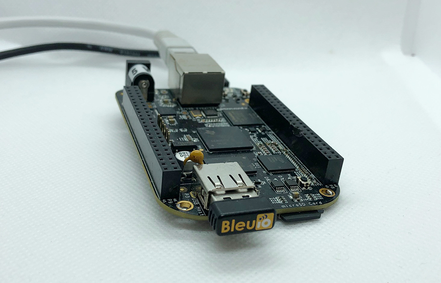
This is a simple example showcasing how to control a BleuIO dongle connected to Beaglebone Black using a python script.

When running the script, it will first ask for the com port where the dongle is connected (usually ‘/dev/ttyACM0’). After that, BleuIO will start advertising. Every 8th second it will turn on one of the onboard Beaglebone Black LEDs whilst changing the BLE advertising name to indicate which LED is on.

We are using the Linux Debian image: ‘OMAP3/DM3730 Debian 9.5 2018-10-07 4GB SD LXQT’ (https://beagleboard.org/latest-images).

2. About the Code

You can get access to the project HERE

https://github.com/smart-sensor-devices-ab/beaglebone_bleuio_example

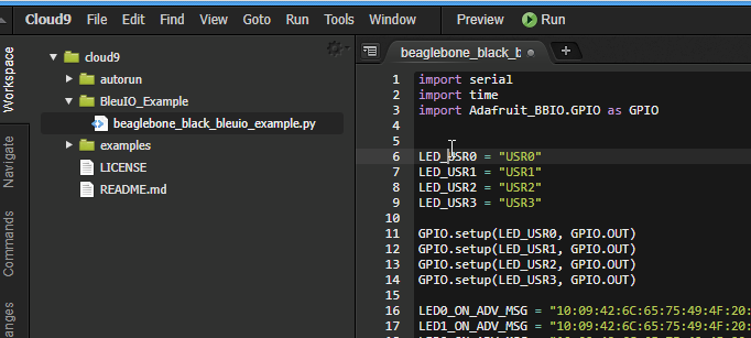
We are using the Adafruit_BBIO python library that comes with the Beaglebone to control the onboard LEDs. First, we define the LEDs names and then set them as GPIO Outputs. Then we define the advertising messages that the BleuIO will switch between. Lets break one down:

“10:09:42:6C:65:75:49:4F:20:4C:45:44:20:30:20:4F:4E:”

“10” is the size of the advertising packet in HEX.
“09” is the flag for the device name (Complete Local Name).
“42:6C:65:75:49:4F:20:4C:45:44:20:30:20:4F:4E” is the packet itself, translated from HEX to ASCII it says: “BleuIO LED 0 ON”

Afterward, the user is presented with a message to input the com port the BleuIO is connected to. If you are not using a USB Hub the port should be ‘/dev/ttyACM0’.

You can change the comport name in the Python script and fill in your COM port.

com_input = “/dev/ttyACM0”

The script continues into the main loop, where it will first make sure all LEDs are off and then start BLE advertising.

The loop iterates through all four LEDs. In every iteration, it turns one LED on and advertises the LED name then continues to the next LED. This will continue until the script is aborted.

import serial
import time
import Adafruit_BBIO.GPIO as GPIO


LED_USR0 = "USR0"
LED_USR1 = "USR1"
LED_USR2 = "USR2"
LED_USR3 = "USR3"

GPIO.setup(LED_USR0, GPIO.OUT)
GPIO.setup(LED_USR1, GPIO.OUT)
GPIO.setup(LED_USR2, GPIO.OUT)
GPIO.setup(LED_USR3, GPIO.OUT)

LED0_ON_ADV_MSG = "10:09:42:6C:65:75:49:4F:20:4C:45:44:20:30:20:4F:4E:"
LED1_ON_ADV_MSG = "10:09:42:6C:65:75:49:4F:20:4C:45:44:20:31:20:4F:4E:"
LED2_ON_ADV_MSG = "10:09:42:6C:65:75:49:4F:20:4C:45:44:20:32:20:4F:4E:"
LED3_ON_ADV_MSG = "10:09:42:6C:65:75:49:4F:20:4C:45:44:20:33:20:4F:4E:"

# Turn off all LEDs
GPIO.output(LED_USR0, GPIO.LOW)
time.sleep(0.1)
GPIO.output(LED_USR1, GPIO.LOW)
time.sleep(0.1)
GPIO.output(LED_USR2, GPIO.LOW)
time.sleep(0.1)
GPIO.output(LED_USR3, GPIO.LOW)
time.sleep(0.1)

print("\nBlueIO BeagleBone Example!\n\n")
connecting_to_dongle = 0
com_input = ""

start_input = 0
valid_input = 0
while start_input == 0:
    com_input = input(
        "Enter Com port of Dongle (default for BeagleBone: '/dev/ttyACM0'):\n>>"
    )
    print("\nComport to use: " + com_input)
    input_continue = input(
        "If your happy with your choice just press Enter to continue the script. Else type E to exit or R to redo your choice. \n>>"
    )
    if input_continue.upper() == "E":
        start_input = 1
    elif input_continue.upper() == "":
        start_input = 1
    elif input_continue.upper() == "R":
        valid_input = 0
        start_input = 0
if input_continue.upper() == "E":
    print("Exiting script...")
    exit()

console = None

while 1:
    try:
        print("Please wait...")
        time.sleep(0.5)
        console.write(str.encode("AT+DUAL"))
        console.write("\r".encode())
        time.sleep(0.5)
        print("Starting Advertising...")
        console.write(str.encode("AT+ADVSTART"))
        console.write("\r".encode())
        time.sleep(0.5)
        led_turn = 0
        # Turn off all LEDs
        GPIO.output(LED_USR0, GPIO.LOW)
        time.sleep(0.1)
        GPIO.output(LED_USR1, GPIO.LOW)
        time.sleep(0.1)
        GPIO.output(LED_USR2, GPIO.LOW)
        time.sleep(0.1)
        GPIO.output(LED_USR3, GPIO.LOW)
        time.sleep(0.1)
        while True:
            if led_turn == 0:
                print("\nTurning LED USR0 ON")
                console.write(str.encode("AT+ADVRESP="))
                console.write(LED0_ON_ADV_MSG.encode())
                console.write("\r".encode())
                GPIO.output(LED_USR0, GPIO.HIGH)
                GPIO.output(LED_USR1, GPIO.LOW)
                GPIO.output(LED_USR2, GPIO.LOW)
                GPIO.output(LED_USR3, GPIO.LOW)
                led_turn = led_turn + 1
            elif led_turn == 1:
                print("\nTurning LED USR1 ON")
                console.write(str.encode("AT+ADVRESP="))
                console.write(LED1_ON_ADV_MSG.encode())
                console.write("\r".encode())
                GPIO.output(LED_USR0, GPIO.LOW)
                GPIO.output(LED_USR1, GPIO.HIGH)
                GPIO.output(LED_USR2, GPIO.LOW)
                GPIO.output(LED_USR3, GPIO.LOW)
                led_turn = led_turn + 1
            elif led_turn == 2:
                print("\nTurning LED USR2 ON")
                console.write(str.encode("AT+ADVRESP="))
                console.write(LED2_ON_ADV_MSG.encode())
                console.write("\r".encode())
                GPIO.output(LED_USR0, GPIO.LOW)
                GPIO.output(LED_USR1, GPIO.LOW)
                GPIO.output(LED_USR2, GPIO.HIGH)
                GPIO.output(LED_USR3, GPIO.LOW)
                led_turn = led_turn + 1
            elif led_turn == 3:
                print("\nTurning LED USR3 ON")
                console.write(str.encode("AT+ADVRESP="))
                console.write(LED3_ON_ADV_MSG.encode())
                console.write("\r".encode())
                GPIO.output(LED_USR0, GPIO.LOW)
                GPIO.output(LED_USR1, GPIO.LOW)
                GPIO.output(LED_USR2, GPIO.LOW)
                GPIO.output(LED_USR3, GPIO.HIGH)
                led_turn = 0

            time.sleep(8)

    except KeyboardInterrupt:
        GPIO.output(LED_USR0, GPIO.LOW)
        time.sleep(0.1)
        GPIO.output(LED_USR1, GPIO.LOW)
        time.sleep(0.1)
        GPIO.output(LED_USR2, GPIO.LOW)
        time.sleep(0.1)
        GPIO.output(LED_USR3, GPIO.LOW)
        time.sleep(0.1)
        print("Exiting script...")
        exit()
    except:
        print("\n\nDongle not connected.\n")
        connecting_to_dongle = 0
        while connecting_to_dongle == 0:
            try:
                print("Trying to connect to dongle...")
                console = serial.Serial(
                    port=com_input,
                    baudrate=57600,
                    parity="N",
                    stopbits=1,
                    bytesize=8,
                    timeout=0,
                )
                if console.is_open.__bool__():
                    connecting_to_dongle = 1
                    print("\n\nConnected to Dongle in port: " + com_input + ".\n")
            except:
                print(
                    "Dongle not found. Retrying connection to port: "
                    + com_input
                    + "..."
                )
                time.sleep(5)

3. Using the example project

3.1 What you will need

4. How to setup project

4.1 Downloading the project from GitHub

Get access to the project HERE

https://github.com/smart-sensor-devices-ab/beaglebone_bleuio_example

Either clone the project or download it as a zip file and unzip it, into a folder on your BeagleBone.

You can also create a new python file using the Cloud9 IDE from the BeagleBone (run by going to http://192.168.7.2:3000/)

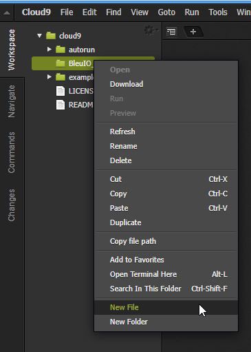
Copy the code and paste it into the newly created file.

4.2 Installing pyserial

To run the script you will need to install the python library pyserial.

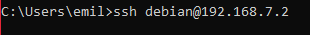
The easiest way of doing this is just connecting to the BeagleBone via shh (the default password is temppwd):

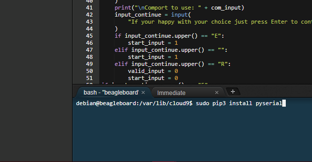
or using the bash tab in the Cloud9 IDE and type:

sudo pip3 install pyserial

5. Running the example

Go to the folder where you have the python script file and run:

(Pyserial needs sudo-privileges to function.)

sudo python3 name_of_script.py

27” Front IP65 Open Frame Touch Panel PC from IBASE

IBASE Technology Inc., a leading manufacturer of embedded boards and industrial computers is proud to release its new OFP-W2700, a series of 27-inch open frame panel PCs suitable for both indoor and semi-outdoor environments. It has IP65 front panel protection, splash-resistant front bezel and can be easily integrated into a custom enclosure, supporting both portrait and landscape display modes in infotainment terminal and self-service kiosk applications in many different industries.

The OFP-W2700 series supports a 250/1000-nits brightness projected capacitive touch screen depending on the DC-input and AC-inlet, wide viewing angle of 178/178 degrees, 4GB system memory and 64GB SSD storage, and is also equipped with four USB, two COM and two RJ-45 LAN ports. It comes in three versions that mainly differ in the type of processor, display output and expansion slots. OFP-W2700-PCI86 features an 8th Gen Intel® i7-8665UE processor, DP and USB Type-C graphics ports, and two M.2 sockets (M2280, E2230); OFP-W2700PCV16 has an AMD Ryzen™ V1605B processor, two HDMI, two M.2 sockets, and a 1000-nits brightness display option; while OFP-W2700PCI50 is powered by an Intel® Atom® x7-E3950 CPU and has one HDMI and two mPCIe sockets.

OFP-W2700 SERIES FEATURES:

  • 27″ wide-screen open frame panel pc with excellent performance
  • 1920 x 1080 resolution and 250-nit & 1000-nit brightness
  • Projected capacitive touch
  • Supports both portrait and landscape display modes
  • Supports IR cut-off solution

The fanless OFP-W2700 series offers a remote power button function and a modular CPU box construction allowing flexible configuration and easy replacement. Measuring 660 x 421 x 98mm (W x H x D), the system can operate in an extended temperature range of -10°C to 50°C and wide voltage input. Both Windows 10 and Linux Kernel 4+ are supported.

For more information, please visit www.ibase.com.tw.

EPC2067 40 V, 409 A(pulsed) eGaN FET

EPC’s EPC2067 is a 40 V eGaN FET for state-of-the-art power density

The EPC2067 from EPC is a 40 V, 1.3 mΩ (typical) eGaN FET with a pulsed current rating of 409 A in a tiny 9.3 mm2 footprint. This device is ideal for applications with demanding high power density performance requirements, including 48 V to 54 V input servers. Lower gate charges and zero reverse recovery losses enable high-frequency operation of 1 MHz and beyond, at high efficiency in a tiny footprint for state-of-the-art power density.

Applications

  • High-frequency DC/DC converters
  • BLDC motor drives
  • Sync rectification for AC/DC and DC/DC

more information: https://epc-co.com/epc/Products/eGaNFETsandICs/EPC2067.aspx

Arduino UNO Mini Limited Edition available on Mouser


Arduino UNO Mini Limited Edition is a special collectible version of the Arduino UNO, designed to celebrate the UNO’s 16th anniversary. The UNO Mini Limited Edition features a compact 26.7mm x 34.2mm form factor, with black and gold trim. This edition of the UNO will be limited to 10,000 units, each individually numbered.

The Arduino UNO Mini Limited Edition is based on the Microchip Technology ATmega328 8-Bit Microcontroller (MCU). The UNO Mini Limited Edition features 14 digital input/output pins (six of which can be used as PWM outputs), six analog inputs, and a 16MHz quartz crystal. The onboard USB-C™ port is controlled by the Atmega16U2 MCU, programmed as a USB-to-serial converter. The UNO Mini Limited Edition can be powered from the USB-C port or an external power supply and includes everything the user needs to support the MCU.

Features

  • Collector’s version of the Arduino UNO limited to 10,000 units
  • Compact 4-layer 26.7mm x 34.2mm PCB, in black and gold
  • 14 digital I/O pins with 6 providing PWM output
  • Six analog input pins
  • 16MHz ceramic resonator
  • USB-C port
  • Powered via USB or with an external power supply
  • Reset button
  • Key components

more information: https://store.arduino.cc/products/uno-mini-le?selectedStore=eu

Qorvo QPC1006 Single-Pole, Triple–Throw (SP3T) RF GaN Switch

Qorvo QPC1006 Single-Pole, Triple–Throw (SP3T) Switch is fabricated on Qorvo’s QGaN25 0.25um GaN on SiC production process. Operating from 0.15 to 2.8GHz, the QPC1006 typically supports 50W input power handling at control voltages of 0/−40V for CW and pulsed RF operations. This switch maintains a low insertion loss of less than 1.0dB and greater than 30dB isolation, making it ideal for high-power switching applications across defense and commercial platforms. The Qorvo QPC1006 is offered in a 4mm x 4mm plastic overmolded QFN package.

Features

  • SP3T
  • 0.15 to 2.8GHz frequency range
  • 50W input power
  • < 1.0dB insertion loss
  • > 30dB typical isolation
  • 50ns switching speed
  • 0V/−40V control voltages
  • 4mm x 4mm x 0.85mm package dimensions

Block Diagram

more information: https://www.qorvo.com/products/p/QPC1006

Open up new IoT possibilities with Seeed XIAO BLE for TinyML and Seeed Fusion PCBA service

Seeed Studio has just released the highly anticipated addition to the XIAO series, Seeed XIAO BLE – nRF52840, a powerful Bluetooth LE microcontroller supporting multiple protocols including Bluetooth 5.0, NFC and Zigbee.

What’s so special about it?  Seeed XIAO BLE and the advanced version, Seeed XIAO BLE Sense are designed for wearable devices and Internet of Things projects, taking advantage of the Nordic nRF52840 MCU’s Bluetooth capabilities of working at long distances, at low power yet with high performance.

The onboard antenna, small size and surface-mountable design make it highly suitable for connected, wearable designs, Internet of Things projects and the possibilities to run AI using TinyML and TensorFlow™ Lite.

Get inspired! To better support Internet of Things developers and enthusiasts to utilize this tiny yet feature-rich board, and accelerate the implementation of IoT industry, smart wear projects and TinyML, Seeed has launched a sponsorship event, manufacture your Seeed XIAO BLE prototype for free with Seeed Fusion PCBA service.

What is Seeed XIAO BLE?

Seeed XIAO BLE – nRF52840 is a low-power, ultra-small size, super cost-effective Bluetooth development board based on the powerful Bluetooth 5.0 MCU — Nordic nRF52840.

What are the key features of Seeed XIAO BLE?

One look at Seeed XIAO BLE and it’s hard to imagine that this cute board is a powerful wireless development board. Sharing the same form-factor with another Seeed favorite, Seeed XIAO BLE uses the thumb-size, surface-mountable design as other boards in the XIAO family. But on this tiny board is the powerful Bluetooth ARM Cortex®-M4 MCU, Nordic nRF52840 with Bluetooth 5.0 BLE, NFC and Zigbee support, an onboard antenna, battery management chip and 2MB high-speed QSPI flash for MicroPython and CircuitPython programming.

In addition to its small size and battery management, the ultra-low power consumption with a deep sleep current of less than 5μA makes it ideal for battery-powered IoT applications, wearables and small projects. And with the onboard QSPI flash, Seeed XIAO BLE is fully compatible with Arduino IDE & MicroPython/CircuitPython programming languages, and the large comprehensive libraries make it easy to get started with IoT projects.

With new wireless capabilities and as the smallest and most versatile nRF52840 development board available, Seeed XIAO BLE is set to be a gamechanger in the IoT and wearables space.

Get one piece of your Prototype Seeed XIAO BLE design manufactured for free with Seeed Fusion PCBA Service

When the original Seeeduino XIAO was launched, many engineers and makers alike were interested in using XIAO, and we received a lot of positive feedback from our customers in forums and on social media platforms.

Therefore, in order to stimulate enthusiasm and help commercial customers land more productive and valuable landing projects. Seeed are sponsoring Seeed XIAO BLE -nRF52840 designs with the Seeed Fusion PCBA service.

How to apply:

All you need to do is fill in the form and complete your Seeed XIAO BLE design.

Please click the link and fill in the form: https://forms.gle/qKQhz7te5JDPPkdD8

Then add your order to the cart and we will confirm the application and get back to you with a coupon for one free PCBA piece. If you are looking for a powerful Bluetooth LE microcontroller for your next design, don’t miss this opportunity. Committed to providing one-stop electronic hardware services for over a decade, Seeed Fusion has the expertise and engineering insight to deliver streamlined PCB assembly at low costs and is equipped with a wide range of value-added services and capabilities.

Take advantage of the Free Design for Assembly review and Free functional testing with Seeed Fusion PCBA service now. Business users will also be interested in Seeed’s free prototyping sponsorship for business users. When your product reaches the batch production stage, we will deduct all the prototyping costs for that design up to 6% of the batch production value. If you are very interested in our product, but do not want to draw schematic and lay out by yourself for some reason, you are welcome to experience our ODM service. For more information, please contact fusion@seeed.cc for help.

ADLINK releases its first SMARC module based on Qualcomm QRB5165

ADLINK releases its first SMARC module based on Qualcomm QRB5165 enabling high-performance robots and drones at low power Integrated IoT technologies provide on-device AI capabilities at the edge.

ADLINK Technology Inc., a global leader in edge computing, released the LEC-RB5 SMARC module –its first SMARC AI-on-Module based on a Qualcomm Technologies, Inc. processor. The Qualcomm QRB5165 processor is designed for robotics and drones applications and integrates several IoT technologies in a single solution. The LEC-RB5 SMARC module provides on-device artificial intelligence (AI) capabilities, support for up to 6 cameras, and low power consumption. It is capable of powering robots and drones in consumer, enterprise, defense, industrial and logistics sectors.

“This high performing SMARC module is a good option for the next generation of high-compute, low power robots and drones,” said Henri Parmentier, Senior Product Manager, ADLINK. “It empowers customers to do everything they need for complex AI and deep learning workloads at the edge without relying on the cloud.”

“Qualcomm Technologies’ portfolio of leading robotics and drones solutions is driving next-generation use cases including autonomous deliveries, mission critical use cases, commercial and enterprise drone applications and more. The Qualcomm QRB5165 solution supports the development of next generation high-compute, AI-enabled, low power robots and drones for the consumer, enterprise, defense, industrial and professional service sectors that can be connected by 5G. The ADLINK LEC-RB5 SMARC module will support the proliferation of 5G in robotics and intelligent systems,”

said Dev Singh, Senior Director, Business Development and General Manager of Robotics, Drones and Intelligent Machines, Qualcomm Technologies, Inc.

For robotics and autonomous robot solution providers, the LEC-RB5 SMARC module provides the capability to build powerful robots for use in harsh industrial conditions and in temperatures that range from -30° to +85°C. The LEC-RB5 SMARC module features:

  • Qualcomm® Kryo™ 585 CPU (8x Arm Cortex-A77 cores)
  • Qualcomm® Hexagon™ Tensor Accelerator (HTA) running up to 15 trillion operations per second (TOPS)
  • Six cameras support: MIPI CSI cameras CSI0 (2 lanes) and CSI1 (4 lanes)
  • Low power consumption: <12W
  • 82 x 50 mm small size form factor

The LEC-RB5 is part of ADLINK’s portfolio of SMARC form factors that support both ARM and x86 designs. ADLINK has worked closely with Qualcomm to design a smart, powerful solution for next generation IoT applications. The module provides enhancements for computer vision (CV) applications with reduced latencies for real time image processing decisions, freeing up capacity for other critical AI applications while delivering mobile-optimized CV experiences. Hardware acceleration for advanced CV applications with on-device AI capable of running complex AI and deep learning workloads with low power makes the LEC-RB5 SMARC module advantageous for a wide variety of industrial and consumer applications.

Visit ADLINK Technology to learn more about the LEC-RB5 SMARC module and development kit.

Universal OPAMP Board for SMD MSOP8 Package

This is easy to build and very useful project for hobbyists and students to learn and create OPAMP-based projects. The project accommodates a single OPAMP in the MSOP8 package. The project provides the user with multiple choices and extensive flexibility for different applications circuits and configurations. It provides the user with many combinations for various circuit types including active filters, differential amplifiers, and external frequency compensation circuits. A few examples of application circuits are given below. OP777 op-amp is the right choice to use or any other MSOP8 op-amp with the same pin configuration as OP777 can be used. It supports dual supply or single supply, Jumper J1 is provided to use this board with a single supply, D1 is the power LED.

Note: Refer to example circuit to test the board, it is a bistable multivibrator, with a single supply and Jumper J1 closed.

Credits: All example schematics are from Analog Devices application notes.

Features

  • Single or Dual Supply User-defined (Jumper)
  • 4 Pin Male Header Connector for inputs
  • 3 Pin Male Header for Supply input (Single or Dual)
  • Jumper J1 Close for single Supply, Open for Dual Supply
  • LED D1 Power LED
  • Any MSOP8 Op-Amp Can be used (Pin configuration compatible OP777)
  • PCB Dimensions 37.31 x 23.50 mm

Similar Universal OPAMP boards

Schematic

Example Application

5Khz Bistable Multivibrator Example Schematic

Parts List

NO.QNTYREF.DESC
11CN14 PIN MALE HEADER PITCH 2.54MM
21CN22 PIN MALE HEADER PITCH 2.54MM
31CN33 PIN MALE HEADER PITCH 2.54MM
426R1,C1,R2,C2,R3,C3,USER DEFINED
,R4,C4,C5,R6,C6,R7,USER DEFINED
R8,C8,R9,R10,R11,R12,USER DEFINED
R13,C13,R14,R15,R16,USER DEFINED
R18,R5,C7,C14,R19,USER DEFINED
52C9,C11CAPACITOR SMD SIZE 1206
62C10,C12CAPACITOR SMD SIZE 0805
71D1LED RED SMD SIZE 0805
81J1PCB SOLDER JUMPER
91R17ALL RESISTORS SIZE 0805
101U1OP-AMP MSOP8 (OP777)
RESISTORS SMD SIZE 0805PCKGE MSOP8EXAMPLE OP777

Example Application Parts List

BISTABLE MULTIVIBRATOR
NO.QNTY.REF.DESC.MANUFACTURERSUPPLIERPART NO
11CN22 PIN MALE HEADER PITCH 2.54MMWURTHDIGIKEY732-5315-ND
21CN33 PIN MALE HEADER PITCH 2.54MMWURTHDIGIKEY732-5316-ND
31C61K PF /50V SMD SIZE 0805MURATA/YAGEO
41C910uF/25V SMD SIZE 1206MURATA/YAGEO
51C100.1uF/50V SMD SIZE 0805MURATA/YAGEO
61D1LED RED SMD SIZE 0805OSRAMDIGIKEY475-1278-1-ND
71J1CLOSED(PCB JUMPER)PCB SOLDER JUMPER
84R1,R3,R7,R16100K 5% SMD SIZE 0805MURATA/YAGEO
92R8,R90E SMD SIZE 0805MURATA/YAGEO
101R171K 5% SMD SIZE 0805MURATA/YAGEO
111U1OP777ANALOGDIGIKEYOP777ARMZ-REELCT-ND

Connections

Example OPAMP Circuits

Gerber View

Photos

Video

OP777 Datasheet

TOP PCB Companies