Arduino 2-Digit 0.5″ Common Cathode 7 Segment Display Module

This is an Arduino compatible board for creating 2 Digit Display projects. The circuit operates with 5V DC, Connector CN1 is provided for bootloader programming and Arduino firmware upload. A new Atmega328 chip requires a bootloader and Arduino firmware programming, Connector CN1 helps you with both functions. Follow the link below to learn more about programming using Arduino. Arduino code is available as a download to test the board.

Arduino 2-Digit 0.5″ Common Cathode 7 Segment Display Module – [Link]

2.5A Bipolar Stepper Driver with Micro-Stepping, Current and Decay Control – Arduino Compatible

This is an Arduino compatible board that contains an Atmega328 microcontroller and Bipolar Stepper Motor Driver chip STK682-010. This Hybrid IC from ON Semiconductor can deliver up to 2.5A current and it can have an input supply up to 32V DC. It has multiple micro-stepping options such as Full step, 1/2th Step, 1/4th Step, 1/8th Step, 1/16th Step, 1/32th Step, 1/64th Step, 1/128th Step.  PR1 trimmer potentiometer is provided to set the decay, 3.5V Slow Decay, 1.1V to 3.1V Mixed Decay, 0.8V-1V Fast Decay, and PR2 Trimmer Potentiometer provided to set the output current. Chopping frequency set to 83.3 Khz using capacitor C5 100PF. Micro-Stepping can be set with the help of jumper J1, J2, J3. This board is by default enabled since the enable pin has a pull-up resistor, but you can provide a low signal to disable the motor driver chip. Atmega328D provides Direction pulse, Step pulse, Enable control, etc. The IC has built-in automatic half current functions to reduce the vibrations & current while the motor is in static mode. It is important to use a heatsink on the motor driver chip. Refer to the micro-stepping table to set the micro-stepping. Board requires a Motor power supply as well logic supply 5Vdc.

2.5A Bipolar Stepper Driver with Micro-Stepping, Current and Decay Control – Arduino Compatible – [Link]

Mini-ITX Motherboard with AMD Ryzen™ Embedded V1000/R1000 Processor Targets Graphics-Driven Applications – GMB140

Axiomtek Gaming – a business unit of Axiomtek, a leading designer and manufacturer of PC-based industrial products – is pleased to introduce the GMB140, its powerful Mini-ITX motherboard with the AMD Ryzen™ Embedded V1000/R1000 processor. With an effective procurement strategy plus a good relationship with AMD, Axiomtek can deliver the GMB140 with a short lead time to satisfy customers’ needs – either in the gaming industry or in the retail or healthcare industry – at a time of a global material shortage.

The compact GMB140 provides powerful computing with the AMD “Zen” CPU and brilliant image processing performance with the AMD Radeon™ Vega Graphics to deliver stunning visual experiences. The GMB140 integrated with the high-performance CPU, GPU and extensive I/O offers superior computing performance and multi-display capability, making it suitable for graphics-driven embedded applications such as digital casino gaming machines, medical imaging, interactive kiosks, control rooms and video surveillance, and more.

“To meet the ever-increasing demand for a multi-screen, high resolution, immersive player experience in casino slot machines, the GMB140 is built with the AMD Ryzen™ Embedded V1000/R1000 SoC with up to 3.6 TFLOPS compute performance. Featuring the AMD Radeon™ Vega Graphics, the GMB140 enables up to four independent displays in brilliant 4K resolution via DisplayPort++ for breakthrough digital casino gaming experiences,” said Ted Loo, product manager of Gaming Division at Axiomtek. “Moreover, its Trusted Boot feature has been verified by Gaming Laboratories International (GLI) to ensure an embedded device starts safely and securely by preventing unauthorized software from taking control of the device at boot-up. TPM 2.0 hardware security function as well as hybrid encryption with RSA-2048 and AES256 are also available for critical information security.” “We are now accepting pre-orders for a total of up to one thousand pieces of GMB140. And they are expected to be available in January 2022,” he added.

The GMB140 comes with two DDR4 SO-DIMM sockets with a memory capacity of up to 32GB. For flexible gaming I/O module, it offers expandability with one PCIe x16 slot and one PCIe Mini Card slot. For rich I/O interfaces, it has seven USB ports, six RS-232 ports, HD audio 5.1-CH Line-out, two GbE LAN ports, two SATA 3.0 ports, and 8-bit GPIO. Furthermore, the GMB140 supports an optional 9-bit serial port for source code SAS 6.02 protocol. It also supports lifetime long-term supply.

Advanced Features:

  • High-performance AMD platform
  • Supports up to 4 independent displays via DisplayPort++
  • V1000 Series: 4 DisplayPort++
  • R1000 Series: 3 DisplayPort++
  • GLI verified Trusted Boot
  • Extension PCIe I/F for gaming I/O module
  • Optional support 9-bit serial port for SAS 6.02
  • Lifetime long-term supply

The GMB140 is available for purchase now. For more product information or customization services, please visit our global website at http://gaming.axiomtek.com or contact one of our sales representatives at info@axiomtek.com.tw.

Bluetooth Low Energy (BLE) Tutorial for Arduino using BleuIO

1. Introduction

The project is a simple example showcasing a quick way to setup an Arduino with a USB Host Shield as a USB CDC Host capable of communicating with the BleuIO Dongle.

When a BleuIO Dongle is connected to the USB port, the BleuIO Dongle will start advertising. It will then act as a terminal, taking input and sending data to the Arduino Virtual Com Port.

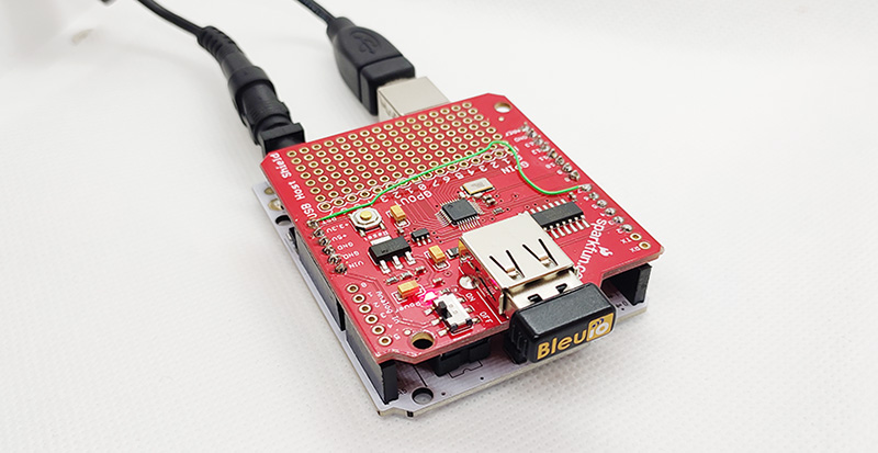
We have used an Arduino Uno Rev. 3 with SparkFun’s USB Host Shield (DEV-09947) for this example.

2. About the Code

You can get the project HERE

https://github.com/smart-sensor-devices-ab/arduino_bleuio_example

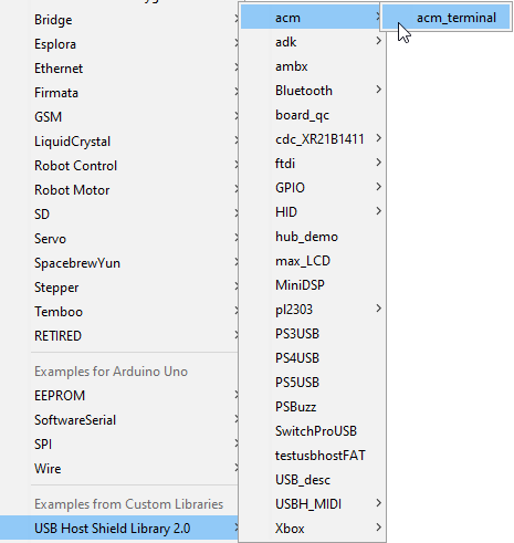
This project is based on the ‘acm_terminal’ example in the Host USB Shield Library 2.0

The largest possible max.packet size for the function Acm.RcvData() is 64 bytes, so to accommodate the amount of data we will receive, we are using three buffers to receive the data from the BleuIO Dongle.

If the buffers have received any data, we print it out to the serial terminal connected to the Virtual COM Port.

void loop()
{
    Usb.Task();

    if( Acm.isReady()) {
       uint8_t rcode;
       uint8_t rcode2;
       uint8_t rcode3;

       /* reading the keyboard */
       if(Serial.available()) {
         uint8_t data= Serial.read();
         /* sending to the BleuIO Dongle */
         rcode = Acm.SndData(1, &data);
         if (rcode)
            ErrorMessage<uint8_t>(PSTR("SndData"), rcode);
       }//if(Serial.available()...

        if(start_flag == 0x00)
        {
            rcode = Acm.SndData(strlen((char *)START_CMDS), (uint8_t *)START_CMDS);
            if (rcode)
            {
                ErrorMessage<uint8_t>(PSTR("SndData"), rcode);
            }

          start_flag = 0x01;
        }
        /* reading the BleuIO Dongle */
        uint8_t  buf[64];
        uint16_t rcvd = 64;
        uint8_t  buf2[64];
        uint16_t rcvd2 = 64;
        uint8_t  buf3[64];
        uint16_t rcvd3 = 64;
        uint8_t  dongle_input[3*64];
        uint16_t input_indx = 0;

        memset(dongle_input, 0, sizeof(dongle_input));

        rcode = Acm.RcvData(&rcvd, buf);
        delay(1);
        rcode2 = Acm.RcvData(&rcvd2, buf2);
        delay(1);
        rcode3 = Acm.RcvData(&rcvd3, buf3);
         if (rcode && rcode != hrNAK)
         {
            ErrorMessage<uint8_t>(PSTR("Ret"), rcode);
         }

         if (rcode2 && rcode2 != hrNAK)
         {
             ErrorMessage<uint8_t>(PSTR("Ret"), rcode2);
         }

         if (rcode3 && rcode3 != hrNAK)
         {
             ErrorMessage<uint8_t>(PSTR("Ret"), rcode3);
         }


            if( rcvd ) { //more than zero bytes received
              for(uint16_t i=0; i < rcvd; i++ ) {
                Serial.print((char)buf[i]); //printing on the screen
                dongle_input[input_indx] = buf[i];
                input_indx++;
              }
            }

            if( rcvd2 ) { //more than zero bytes received
              for(uint16_t i=0; i < rcvd2; i++ ) {
                Serial.print((char)buf2[i]); //printing on the screen
                dongle_input[input_indx] = buf2[i];
                input_indx++;
              }
            }

            if( rcvd3 ) { //more than zero bytes received
              for(uint16_t i=0; i < rcvd3; i++ ) {
                Serial.print((char)buf3[i]); //printing on the screen
                dongle_input[input_indx] = buf3[i];
                input_indx++;
              }
            }
            dongle_input[input_indx] = 0x00;

            // Example on a way for the Arduino to react to BleuIO events
            if(strlen((char *)dongle_input) != 0)
            {
              if(strstr((char *)dongle_input, "handle_evt_gap_connected") != NULL)
              {
                Serial.print("<<CONNECTION DETECTED!>>");
              }
              else if(strstr((char *)dongle_input, "handle_evt_gap_disconnected") != NULL)
              {
                Serial.print("<<CONNECTION LOST!>>");
              }
            }
    }//if( Usb.getUsbTaskState() == USB_STATE_RUNNING..
}

We also store the latest data from the dongle into the dongle_input buffer and run it through a simple “parser” to showcase an easy way of how you can react to events and have the Arduino do something.

In this example, we are explicitly looking for BLE connection or disconnect events. When found, we just print out “<<CONNECTION DETECTED!>>” or “<<CONNECTION LOST!>>” to the terminal.

3. Using the example project

3.1 What you will need

3.2 Requirments for the SparkFun board

  • With the SparkFun board, it seems like you MUST supply external power on Vin or the barrel jack. 5V from the USB cable did not work.
  • You must also apply a jumper from pin D7 to RESET.

4. How to setup project

4.1 Downloading the project from GitHub

Get project HERE

https://github.com/smart-sensor-devices-ab/arduino_bleuio_example

Either clone the project or download it as a zip file and unzip it, into your Arduino folder.

4.2 Downloading the USB Host Shield Library 2.0

Either download the Library from Here (https://felis.github.io/USB_Host_Shield_2.0/) and place the folder into your libraries folder inside your Arduino folder. (For information on installing libraries, see: http://www.arduino.cc/en/Guide/Libraries)

Or download it through the Arduino IDE:

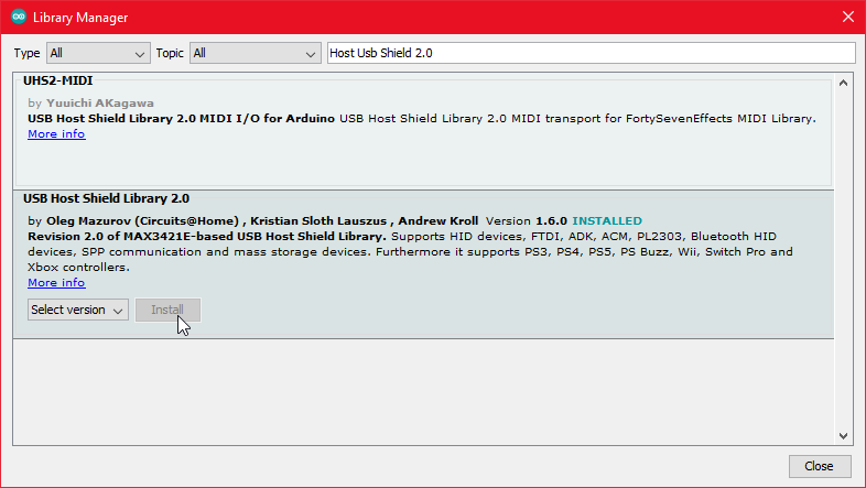
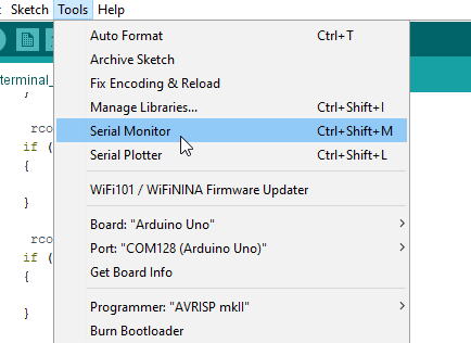
In Arduino IDE choose Sketch>Include Library>Manage Library

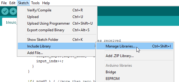
Search for USB Host Shield Library 2.0 and click ‘Install’

5. Running the example

In Arduino IDE click the upload button to upload the project to your Arduino.

Open up the ‘Arduino Uno Viritual COM Port’ with a serial terminal emulation program like TeraTerm, Putty or CoolTerm.Serial port Setup:
Baudrate: 115200
Data Bits: 8
Parity: None
Stop Bits: 1
Flow Control: None

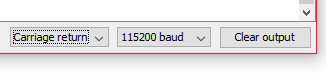
Or inside the Arduino IDE open up Arduino Monitor and in the bottom right corner select ‘Carriage Return’ and ‘115200 baud’

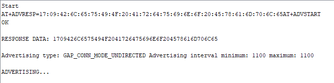
You should see the word ‘Start’ and then see the dongle running two commands: setting response data and starting the advertising. You can now type commands to the dongle.

Radiation dosimeters weigh in at just 17 gm

Teledyne e2v HiRel announced the availability of 3 new radiation dosimeter models that further broaden its popular range of radiation measurement devices. Aimed at high altitude aerospace applications and all space applications from GEO satellites and LEO constellations to scientific exploration, each new model occupies minimal volume and adds only 17g weight to any mission.

For many space and high altitude aerospace applications, it is of critical importance to know the amount of radiation that the platform has been subjected to. Teledyne’s Microdosimeter NuDOS001, NuDOS002, and NuDOS003 measures the Total Ionizing Dose (TID) of Low-, Medium-, and High-LET (Linear Energy Transfer) radiation and can be polled in real-time to monitor events as they happen. Deploying a system of all three models can provide spectral information about the environment.

Devices are available for ordering and shipment now, from Teledyne e2v HiRel or an authorized distributor, in commercial versions and with the option of Class H equivalent screening.

more information: https://www.teledynedefenseelectronics.com/e2vhrel/products/Pages/Radiation%20Micro%20Dosimeter.aspx

Triple-band antenna is available at Mouser

Johanson Technology 2450AD18A6050 Mini Ultra-Wide Triple Band Antenna

Johanson Technology 2450AD18A6050 Mini Ultra-Wide Triple Band Antenna is a miniature BLUETOOTH®/Wi-Fi® 6E and UWB internal chip antenna that operates in the 2400MHz to 2500MHz, 4900MHz to 5850MHz, and 5850MHz to 7200MHz bands. With IEEE 802.11 ax compliance, the surface mount 2450AD18A6050 Antenna offers a single feed point with radiation efficiencies of up to 85%. The 2450AD18A6050 Mini Ultra-Wide Triple Band Antenna features a corner PCB mount design in an EIA 1206 (3216 metric) package measuring 3.20mm x 1.60mm x 0.50mm in dimension. Other features include a 50Ω impedance, 3W maximum power capacity, and a -40°C to +85°C operating temperature range.

Features

  • 2.45GHz/6.05GHz BT/Wi-Fi and UWB ceramic mini antenna
  • Single-feed
  • Corner mount
  • Frequency bands
    • 2400MHz to 2500MHz
    • 4900MHz to 5850MHz
    • 5850MHz to 7200MHz
  • Peak gain (YZ-plane)
    • +2.0dBi typical for 2400MHz to 2500MHz
    • +1.5dBi typical for 4900MHz to 5850MHz
    • +2.5dBi typical for 5850MHz to 7200MHz
  • 5dB to 6dB minimum return loss
  • Average gain (YZ-plane)
    • -1.5dBi typical for 2400MHz to 2500MHz
    • -2.0dBi typical for 4900MHz to 5850MHz and 5850MHz to 7200MHz
  • 74% to 85% radiation efficiency
  • 50Ω impedance
  • 3W maximum power capacity
  • Temperature ranges
    • -40°C to +85°C operating
    • +5°C to +35°C storage
  • 3.20mm x 1.60mm x 0.50mm in dimension (LxWxT)

Applications

  • Gaming (VR/AR)
  • Audio
  • Video
  • Bluetooth
  • Wi-Fi 2.4
  • Wi-Fi 5.5
  • Wi-Fi 6
  • Wi-Fi 6E

more information: https://www.johansontechnology.com/datasheets/2450AD18A6050/2450AD18A6050.pdf

Schurter Capacitive Hidden Switch (CHS) Metal Line Switches

Schurter Capacitive Hidden Switch (CHS) Metal Line Switches are intended for use behind non-conductive surfaces, enabling interface designers more flexibility in custom panel designs. These capacitive switches can be used as a single key or in arrays. The standard switches can be mounted behind a glass surface up to 2mm in thickness. The sensitivity level can be adjusted for mounting behind surface overlays such as plastic, porcelain, ceramic, granite, and more. The CHS series does not require mounting holes or switch openings that would allow for the ingress of liquids, dirt, or microbes. Schurter CHS Metal Line Switches are ideal for surfaces that require frequent cleaning, such as vending machines, ticketing kiosks, and other self-service kiosks. Additional applications include architectural design, professional / gourmet kitchens, and industrial. The CHS switches provide a rated lifetime of more than 100 million actuations.

Features

  • Enables design flexibility and invisible installation
  • Easy and hygienic cleaning
  • No mounting holes or switch openings
  • Multicolor illumination
  • Easily installed to the back of a surface with 3M Adhesive transfer tape 468MP
  • Standard sensitivity for glass thickness of up to 2mm
  • Quick and easy installation behind non-conductive materials (glass, plastic, wood, etc.)
  • Wearless, no moving parts
  • Meets IEC/UL 62368-1 standards
  • CE marking
  • RoHS and REACH compliant

Applications

  • Non-conductive surfaces that require frequent cleaning
  • Vending machines
  • Ticketing and other self-service kiosks
  • Architectural design
  • Professional / gourmet kitchens
  • Industrial

Specifications

  • Three variations
    • CHS1 – PCB circuit only
    • CHS2 – housing and RGB backlit illumination
    • CHS3 – potted housing and RGB backlit illumination (ideal for harsh conditions)
  • 30mm x 30mm with minimal mounting depth
  • Rated lifetime of >100 million actuations
  • 5VDC to 28VDC supply voltage
  • -40°C to +85°C operating temperature range

more information: https://ch.schurter.com/it/datasheet/CHS

Diodes Incorporated AP3128 PWM Controller

Diodes Incorporated AP3128 PWM Controller is a peak-current control and multi-mode (QR+CCM) PWM controller. This controller is optimized for high performance, low standby power, and cost-effective offline flyback converters. The AP3128 is designed to enter burst mode at no-load/light-load and minimizes standby power consumption. This controller features a 105kHz maximum switching frequency that clamps the QR frequency to reduce switching power loss and the minimum frequency avoids audible noise. The AP3128 controller offers multi-mode control, soft start during the startup process, frequency foldback for high average efficiency, and secondary winding short protection with FOCP. Typical applications include a cell phone charger, Power Delivery (PD) application, ATX/BTX auxiliary power, Set-Top Box (STB) power supply, open frame switching power supply.

Features

  • Multi-mode control
  • Quasi-Resonant (QR) operation at high line voltage
  • Continuous Current Mode (CCM) operation at low line voltage
  • Non-audible noise quasi-resonant control
  • Soft start during the startup process
  • Frequency fold back for high average efficiency
  • Constant Over Current Protection (OCP)
  • Secondary winding short protection with FOCP
  • Frequency dithering for reducing EMI
  • Useful Pin fault protection:
    • SENSE pin floating
    • FB/optocoupler open/short
  • Comprehensive system protection feature:
    • VCC Overvoltage Protection (VOVP)
    • Overload Protection (OLP)
  • Brown Out Protection (BNO)

Specifications

  • 10V to 50V supply voltage range
  • -40°C to 150°C operating junction temperature range
  • 80kHz (CCM mode) oscillation frequency
  • 1µA startup current
  • -800mA to 300mA output current range
  • 550mW Power Dissipation (PD) at TA < 25°C

Block Diagram

Application Circuit

more information: https://www.diodes.com/part/view/AP3128

MAX17330X22+ Standalone 1-Cell Charger, Fuel Gauge, and Protector

Maxim’s highly integrated charger, fuel gauge, protector, and battery internal self-discharge detection IC for 1-cell lithium-ion/polymer batteries

Maxim’s MAX17330 regulates charge voltage, current, and FET temperature with stand-alone charging supported by flexible configuration in nonvolatile memory. The IC supports the following applications: low-power charging including 1 mA to 500 mA directly from universal 5 V USB, high-power parallel packs (>1000 mA), and protection and charging control, pack or host side.

The MAX17330 ideal diode circuit supports a quick response to system transients and adapter removal with a low voltage drop across the CHG FET.

The IC uses the ModelGauge™ m5 EZ algorithm that combines the short-term accuracy and linearity of a coulomb counter with the long-term stability of a voltage-based fuel gauge to provide industry-leading accuracy. The IC automatically compensates for cell aging, temperature, and discharge rate while providing accurate state-of-charge (SOC) in milliampere-hours or percentage over a wide range of operating conditions.

The IC monitors the voltage, current, temperature, and state of the battery to protect against over/undervoltage, overcurrent, short-circuit, over/undertemperature and overcharge conditions, and internal self-discharge protection using external high-side N-FETs to ensure that the lithium-ion/polymer battery operates under safe conditions which prolong the life of the battery.

Features

  • Nonvolatile programmable stand-alone AccuCharge charger
    • Battery health and programmable safety/protection
    • Overvoltage/overcharge-current
    • Overcharge/discharge/short-circuit current
    • Over/under temperature
  • ModelGauge m5 EZ algorithm
    • Percent, capacity, time-to-empty/full, and age
    • Cycle+™ age forecast
  • Precision measurement without calibration
  • History logging and user data
  • Low quiescent current
  • SHA-256 Authentication to prevent cloning
  • 1.9 mm x 2.5 mm 15-bump 0.5 mm pitch WLP
  • Pushbutton wakeup/factory ship mode (0.5 μA)

Application Circuit

more information: https://www.maximintegrated.com/en/products/power/battery-management/MAX17330.html

MP6650 Single-Phase BLDC Motor Driver features multiple protections

MPS’ 18 V 2 A motor driver features include input OVP, UVLO, RD protection, thermal shutdown, and input reverse protection

MPS’ MP6650 single-phase brushless DC motor driver has integrated power MOSFETs and a Hall effect sensor. The device drives single-phase brushless DC fan motors with up to 2 A of output current. The IC has a 3.3 V to 18 V input voltage range and input line reverse-voltage protection (RVP) to save the external diode on the supply line. The device controls the rotational speed through the PWM signal on the PWM pin. It has a rotational speed detection feature and rotor lock fault indication on the frequency generator (FG)/rotor deadlock (RD) pin with open-drain output. The output speed versus the input duty curve can be configured easily for flexible use.

The MP6650 features a soft on/off phase transition and an automatic phase-lock function of the motor winding BEMF and current to reduce audible fan driver noise and power loss. Full protection features include input overvoltage protection (OVP), undervoltage lockout (UVLO), RD protection, thermal shutdown, and input reverse protection. The MP6650 requires a minimal number of external components to save solution cost and is available in TSOT23-6-L, TSOT23-6-R, TSOT23-6-SL, and TSOT23-6-RSL packages.

Features

  • Embedded Hall sensor with high sensitivity
  • Wide 3.3 V to 18 V operating input range
  • Up to 2 A configurable current limit
  • Integrated power MOSFETs: total 740 mΩ (HS-FET and LS-FET)
  • Configurable speed curve
  • Built-in adjustable speed curve corner setting
  • Automatic phase-lock detection of winding BEMF and current zero-crossing
  • Soft on/off phase transition
  • Rotational speed indicator FG signal
  • 2 kHz to 100 kHz PWM input frequency range
  • Fixed 26 kHz output switching frequency
  • Input line RVP
  • RD protection
  • Thermal protection and automatic recovery
  • Built-in input OVP, UVLO, and automatic recovery
  • Available in TSOT23-6-L, TSOT23-6-R, TSOT23-6-SL, and TSOT23-6-RSL packages

Internal Diagram

more information: https://www.monolithicpower.com/en/mp6650.html

TOP PCB Companies