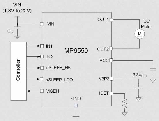
MPS’ H-bridge motor driver consists of four N-channel power MOSFETs and an internal charge pump to generate gate-drive voltages
The MP6550 from Monolithic Power Systems is an H-bridge motor driver consisting of four N-channel power MOSFETs and an internal charge pump to generate gate-drive voltages. The MP6550 is typically used to drive a DC brush motor. According to the logic control, the device operates on a motor power supply voltage from 1.8 V to 22 V, which can supply an output current of up to 2 A. The MP6550 has a PWM input interface, which is compatible with industry-standard devices. Very low standby circuit current can be achieved when the device is disabled. An internal current-sensing circuit provides an output with a voltage proportional to the load current. Cycle-by-cycle current regulation and limiting is also provided. These features do not require the use of a low-value shunt resistor. There are internal shutdown functions for overcurrent protection, short-circuit protection, under-voltage lockout, and overtemperature protection. The MP6550 requires a minimal number of readily available, standard external components and is available in a QFN-12 (2 mm x 2 mm) package.
Features
Wide 1.8 V to 22 V operating input range
2 A continuous driver current
MOSFET on-resistance (HS + LS) 240 mΩ
Cycle-by-cycle current regulation/limit
Built-in 3.3 V reference output
PWM input interface, compatible with industry-standard devices, up to 100 kHz
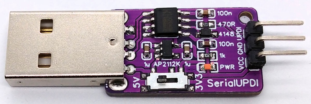
Simple UPDI programmer for tinyAVR, megaAVR and AVR-Dx microcontrollers with voltage selection switch (5V and 3.3V). The programmer works with pyupdi as well as with the Arduino IDE as “SerialUPDI with 4.7k resistor or diode”. It is based on the USB-to-serial chip CH340N.
SerialUPDI Programmer – Simple UPDI programmer for tinyAVR – [Link]
There are many reasons to invest in a home security system especially in today’s day and age – from providing total security of valuables to having the security of persons, and eventually to have that peace of mind that comes with knowing that everything is under your control whether you are home or not.
Reports have shown that 1 out of 3 homes without a security system will likely fall victim to a robbery incident compared to 1 in 250 homes with a security system. This is because most criminals fear either being caught by police or captured by surveillance cameras. So you really cannot underestimate the necessity that comes with having a security system in your home to protect your family and property.
While home security systems can vary depending on the design and targeted use, they all work on the same basic principle of securing entry points or interior spaces regardless of how big or small the house is. What matters really is the number of security components deployed and monitored by the control panel. Some of the places that you’d likely find security systems around the house include entry points like doors and windows, as well as interior spaces containing valuables like art, computers, TVs, coin collections, etc.
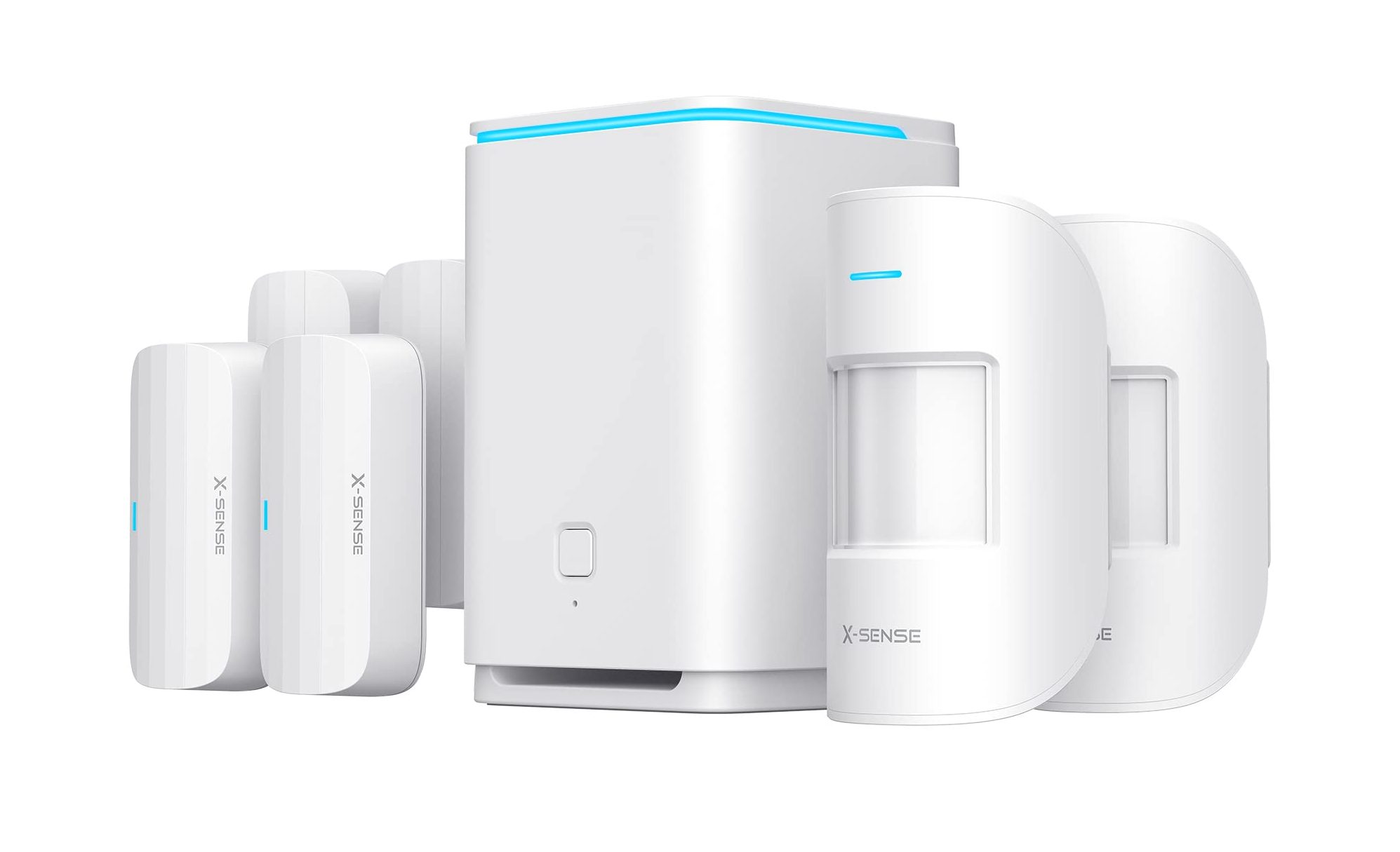
X-sense Smart Home Security Kit
The X-sense home security system is an 8-piece wireless alarm security kit designed by X-sense, a leading global provider of products and services related to home safety. It is a professionally monitored smart home security system with nearly everything you need for maximum protection.
X-Sense home security system offers 24/7 security monitoring and remote control of your house. The security system will also give you an instant notification in case it detects any intrusion or strange moves, so you can take some emergency measures if needed.
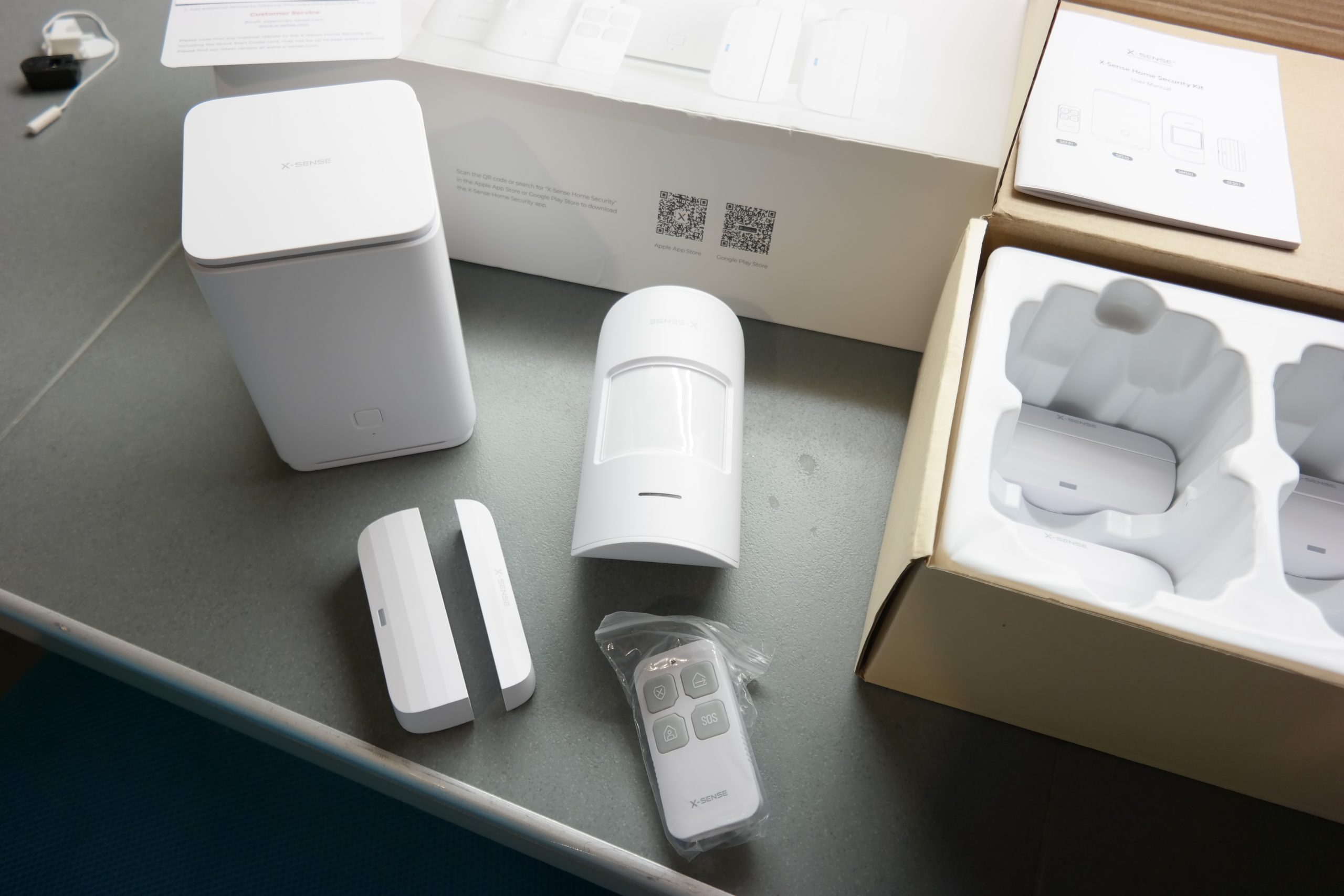
The box includes 2 motion sensors and 4 door/window sensors which is enough to cover most access points to your home, along with the base station and remote control.
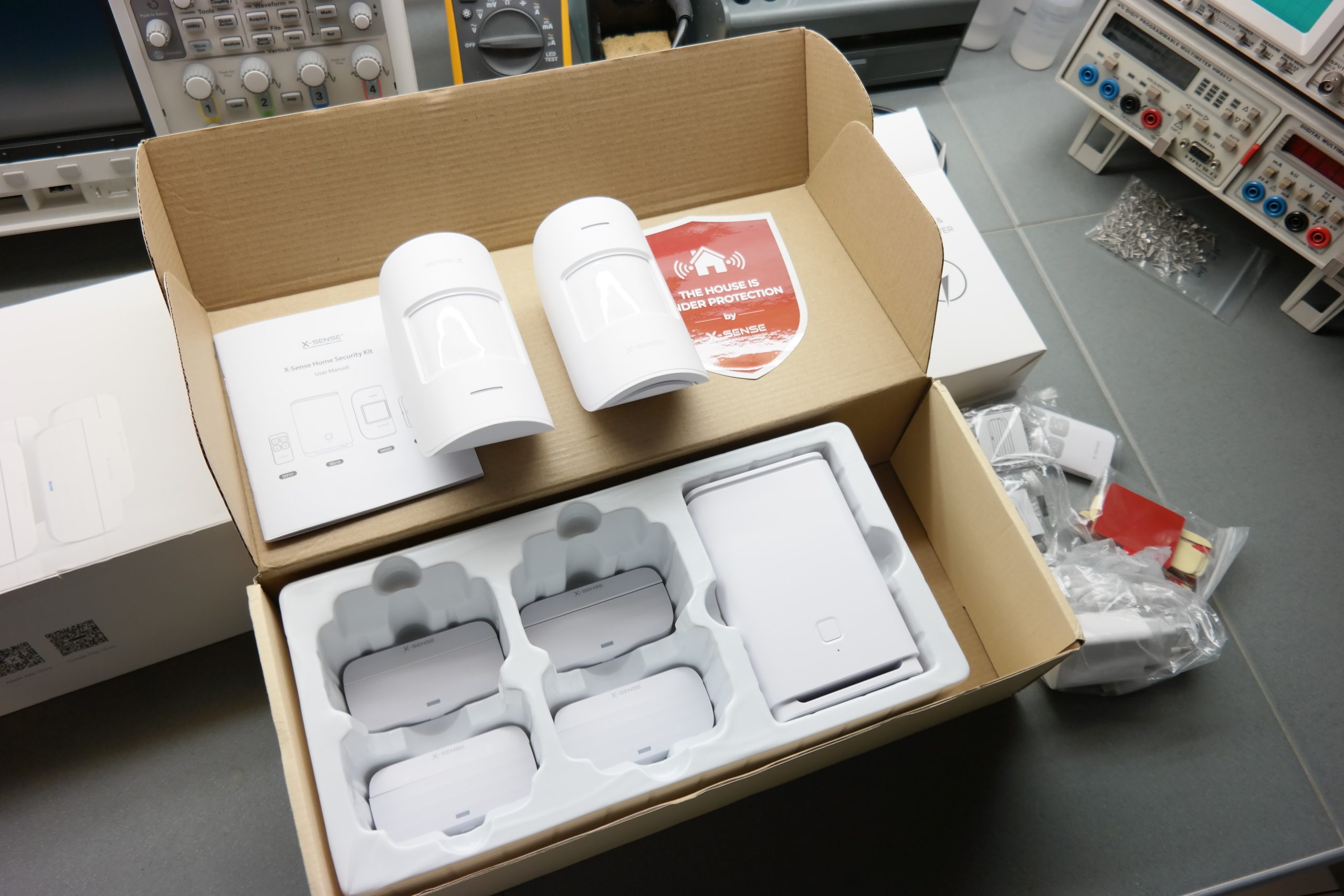
Our first impression of the X-Sense Home Security kit, after opening the box and having a look at the contents inside, is a positive one. Unlike other kits, it includes a fair number of accessories that you’ll need to get your home secured.
The window and door sensors have a nice design to their shape with straight lines that fall with the curve. They feel like good quality plastic.
The base station has a clean, elegant look and has the aesthetics of an Apple product. There is an LED strip that runs around the top which will display different colors and will alert with a red light if an alarm has been triggered and different colors to tell you about any WI-FI problems if you should ever have any. There is a button on the front that can be used to silence the alarm if needed and a reset hole underneath if you ever need to reset it back to its default settings.
The remote control is very small and runs on a CR2032 battery which is replaceable. It has 4 buttons that will arm and disarm your home and away modes, more on that during the setup.
Features of the X-sense Security System
X-sense is fully equipped with just the right set of features for total home safety:
4x entry sensors (you are to mount them on your doors and windows so that if someone opens a door or window the alarm will sound and you will receive a mobile notification from the app. There are tapes and screws provided to help with fixing the sensors).
2x motion sensors that offer movement detection in desired areas (has a maximum of 12m detection range and 110° detection angle)
1x Remote Control
Batteries,
A base station with a built-in battery (the base station is compatible with 2.4 GHz Wi-Fi network)
Dimensions: 15.2″ x 6.6″ x 3.9″
The distance between the sub-device and the base station is as long as 1.25 miles/2000 meters, with a large coverage area, strong wall penetration capability, and more stable transmission. This home security system is extremely safe, using bank-level professional algorithm encryption, anti-counterfeiting, anti-tampering, anti-interference.
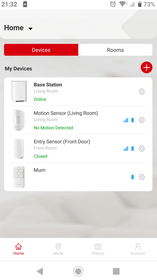
The system was designed in such a way that you can choose to monitor and control it with a remote or via an Android and iOS supported home security app developed by the company. You can customize and set up the system features just the way you like — the base station sound, the brightness level, alarm tones for each sensor, motion sensor sensitivity as well as the away/home modes.
The company also tried to utilize the most advanced monitoring and control technologies while building the system because I can see that X-sense is based on the latest spread spectrum technology that enables a communication range of up to 1.25 miles between the base station and other security devices. So it doesn’t matter how big or structured your home is, X-sense can give a total home coverage, be it a home with basements, or shed, or free-standing garages, or even remote outbuildings.
All these and many more, including the fact that X-sense is easy and fast to install, it’s just a matter of minutes. You don’t need to do any special wiring too as everything you need is ready in the box.
X-sense also has an 1800-mAh built-in backup battery that guarantees about 12 hours of power supply even during a power outage. This way, you can rest assured that your devices are always connected and your security system is available to provide reliable protection.
App Screen
What’s more?
The X-sense security system can also be customized in such a way that suits the user. It works well with Alexa, so when you link the system with your Alexa account, you can arm or disarm the system whenever you want by just speaking to it. Something like “Alexa, arm my home”, or “Alexa, disarm my home”.
What is missing from this alarm system is the numerical keypad that can be used to enter a PIN, but this may be replaced by the remote control you can always have on your keyring or by the Smartphone App.
Pricing and Availability
It is first important to note that buying the X-sense security system is a one-off purchase. You will not be burdened with constant reminders about monthly fees or subscriptions.
The X-sense home security system is available and sells on Amazon for $169 (model with 8 pieces) and $119 (for the model with 5 pieces). This is excluding shipping and import fees though.
The logic NAND function gives the inverted output of the logic AND function. It complements the output of the logic AND function to give the NOT AND (NAND) function. The logic NAND function is the combination of two logic functions that are AND & NOT logics. These AND & NOT logics form a series combination to produce the logic NAND function.
Figure 1: The NAND gate equivalent
The combination of these two logics is symbolized by placing an “Inversion Bubble” at the output of an AND gate. The logic NAND symbol is shown in the following figure along with its Boolean expression. The Boolean expression of the NAND gate is represented by a product of inputs with an overline (¯). The product of inputs expresses AND logic and, whereas, the overline (¯) represents the NOT logic.
Figure 2: The NAND gate symbol with expression
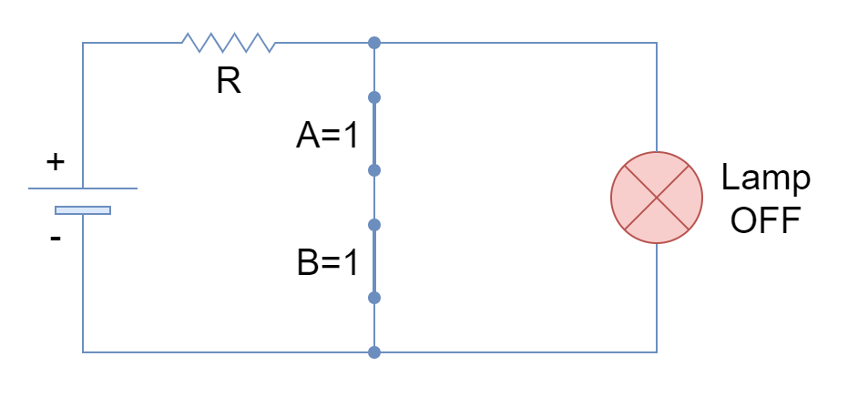
Similar to the logic AND function, the logic NAND function can be represented and explained by switches. From the previous article on Logic AND Function, it is known that AND function can be represented by switches that are placed in series with the output. However, in the logic NAND function, these series switches (inputs) are placed parallel to the output. The representation of a logic NAND function in the form of switches is shown in the following figure.
The logical states of “0” & “1” represent a switch with “Open” & “Closed” positions, respectively.
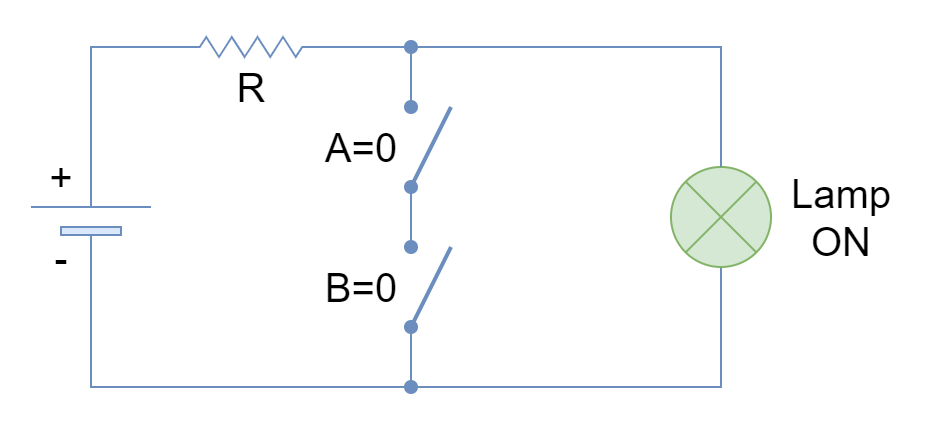
Figure 3: The lamp ON when both switches are open
In the above figure, the current flows through the lamp to turn it ON when both switches (A & B) (inputs) are open (both at logic 0).
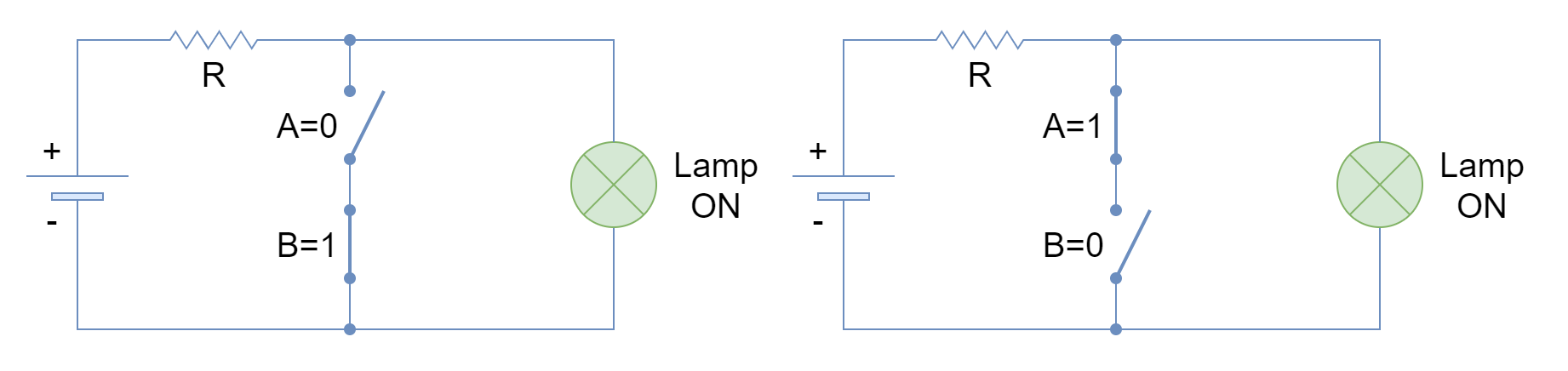
Figure 4: Lamp ON when any switch is open
The closing of any of the switches does not change the state of the lamp and remains ON until both switches are closed.
Figure 5: Lamp OFF when both switches are closed
When both switches are closed (both at logic 1), the current flows through the switches bypassing the lamp and it turns OFF.
The only condition for the lamp to remain OFF is when all of the switches are closed or at a HIGH state. This is in reverse with the logic AND function which, contrarily, turns ON the lamp when all of the inputs are at a HIGH state.
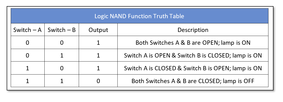
The switches representation of a logic NAND function is expressed in the form of a truth table which is given below:
Construction of NAND logic
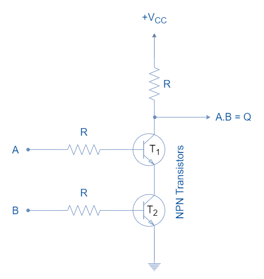
The logic NAND gate can be constructed using Resistor-Transistor Logic (RTL), Transistor-Transistor Logic (TTL), or Complementary Metal-Oxide Semiconductor (CMOS). These, basically, constitute the formation of logical families. The logic NAND gate with two inputs constructed using Resistor-Transistor Logic (RTL) is shown in the following figure.
Figure 6: The Resistor-Transistor Logic (RTL) NAND gate
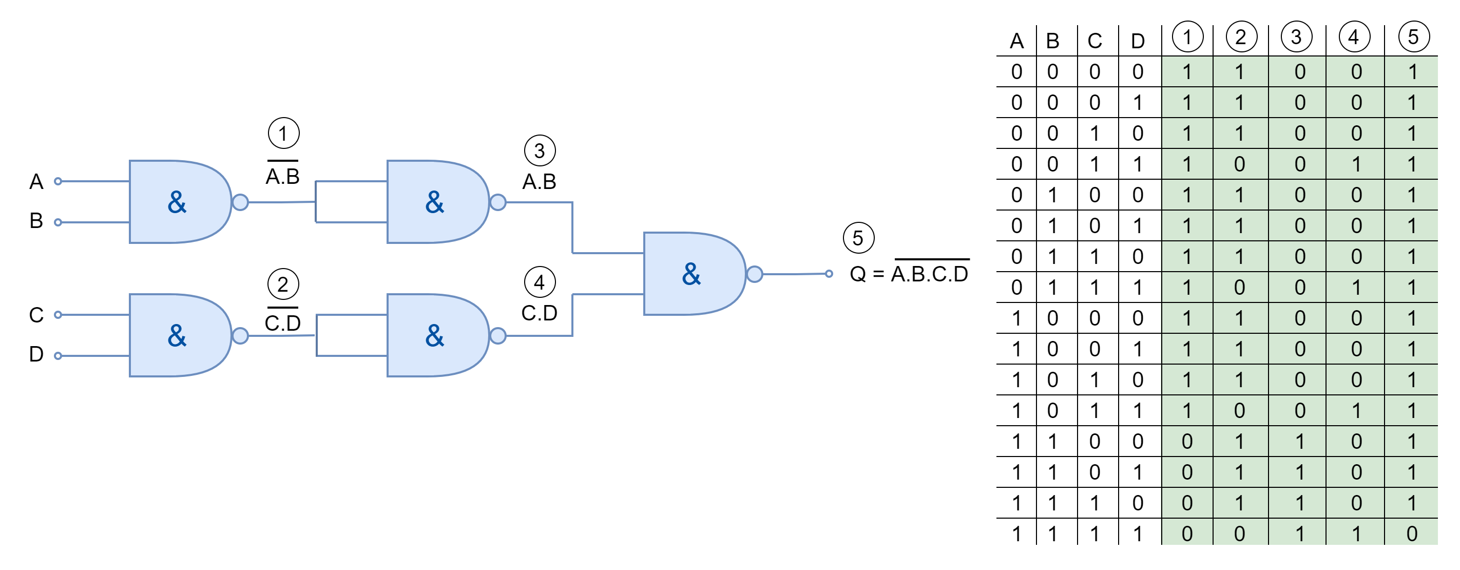
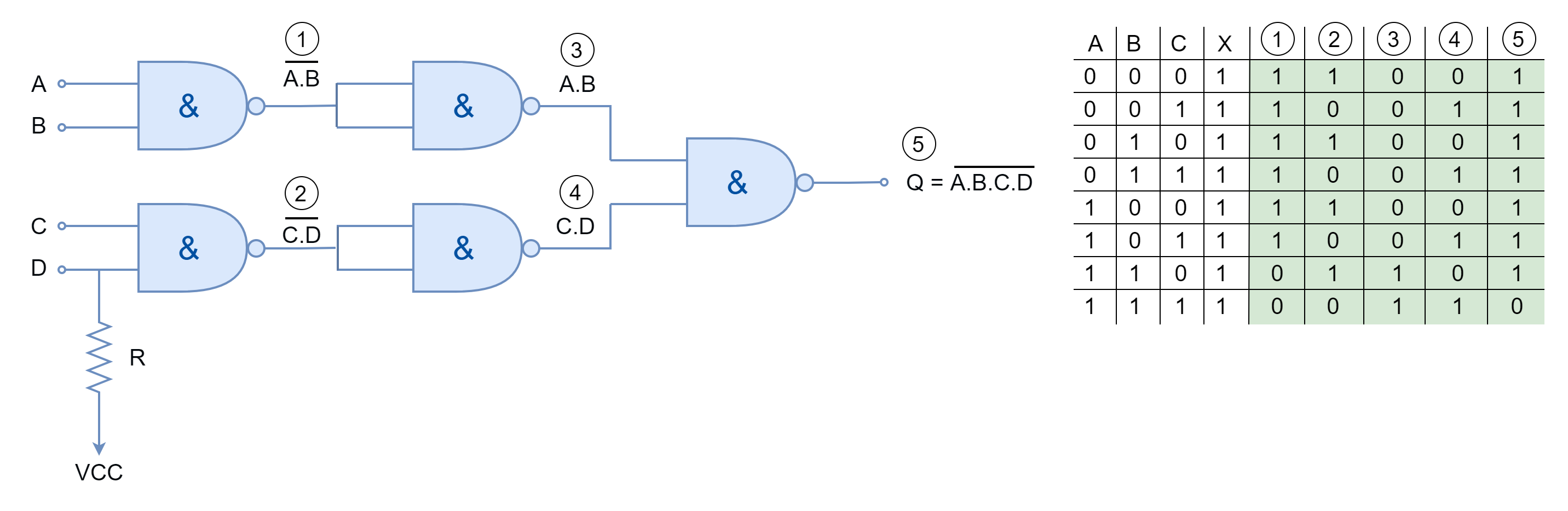
The logic NAND function can be extended to include more than two inputs. In Boolean expression form, the additional input or variable is added to the product with an overline. In logic gates, the NAND gates are cascaded to add in more inputs as shown below.
Figure 7: The logic NAND gate with more than two inputs
Moreover, the logic NAND function with an odd number of inputs can also be achieved by using logic “HIGH” or “1” in Boolean expression form. Whereas, in the case of NAND gates, the other input (unused/ discarded) must be pulled high through a suitable resistor as shown in the following figure.
Figure 8: The logic NAND gate with an odd number of inputs
Universal Gate
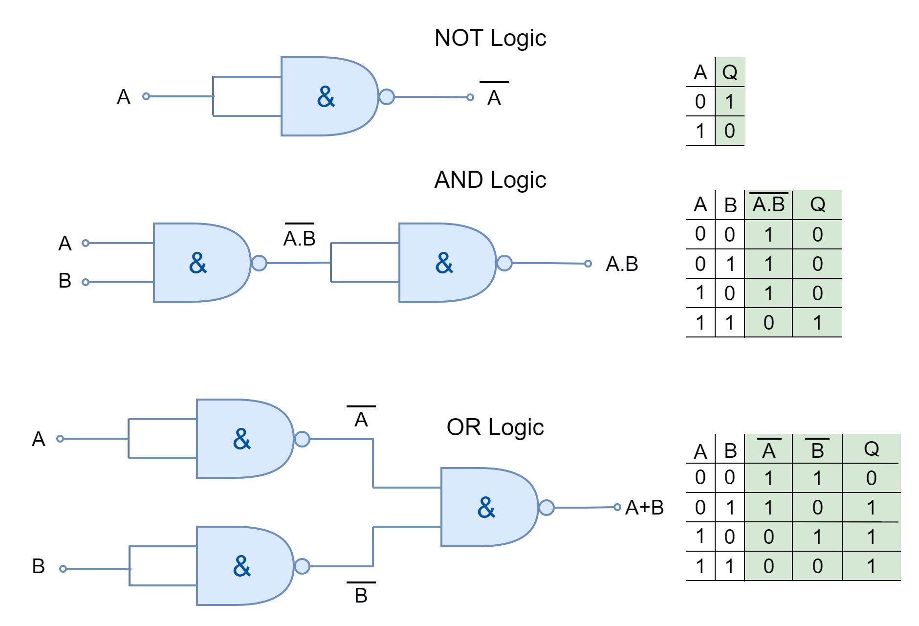
The logic NAND gate is referred to as a Universal Gate as every other logic function can be constructed using it. They can construct all the functions which can be constructed using basic logic gates i.e. AND, OR, and NOT. The construction of basic logic functions using logic NAND gates is shown below.
Figure 9: Basic logic function using NAND gates
Boolean Algebra Laws
Similar to logic AND function, the logic NAND function follows all the Boolean algebra laws and theorems such as Annulment, Identity, Idempotent, Complement, Commutative and Associative Laws which are explained briefly in the Logic AND function.
Commercially Available Logic NAND Gates
The logic NAND gates are available in form of I.C. packages which contain multiple NAND gates with multiple inputs to each gate. The selection depends merely on the application and the number of logic gates are required. They come in both Transistor-Transistor Logic (TTL) and Complementary Metal Oxide Semiconductor (CMOS) family packages. A few commercially available logic NAND gates are given below:
74LS00 Quad 2-input
74LS10 Triple 3-input
74LS20 Dual 4-input
74LS30 Single 8-input
CD4011 Quad 2-input
CD4023 Triple 3-input
CD4012 Dual 4-inputs
Conclusion
The logic NAND function gives output FALSE only when all of its inputs are in a TRUE state.
Any of the inputs in the FALSE state will lead the NAND function to the TRUE output.
The logic NAND function can be represented by an electrical circuit having two series switches in parallel with the load. When any of the switches are closed (input at TRUE state) then supply passes to the load/ lamp to turn it ON.
The logic NAND gate is also known as Universal Gate because it can construct every other logic.
The logic NAND gates can be cascaded together to obtain logic NAND having more than two inputs.
The commercially available packages come in different I.C. packages. Each IC package contains multiple NAND gates.
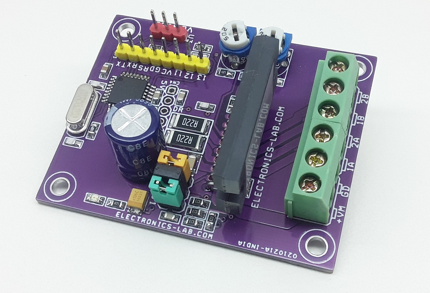
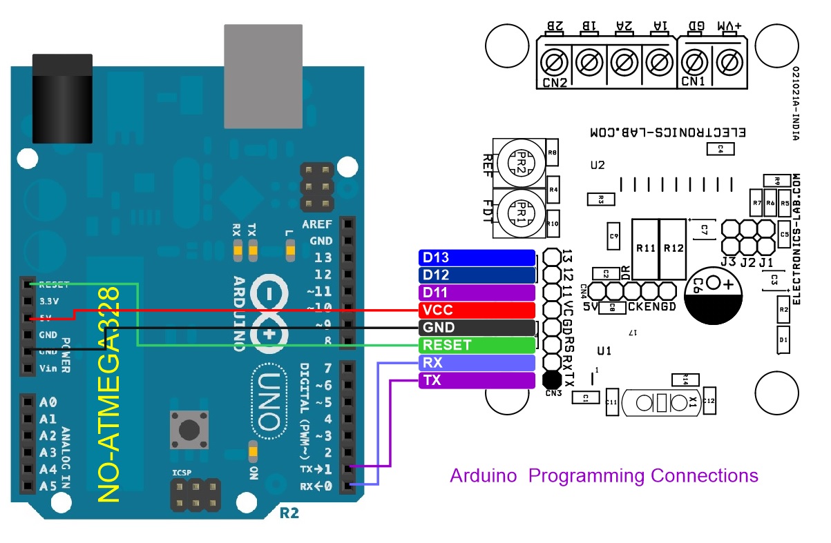
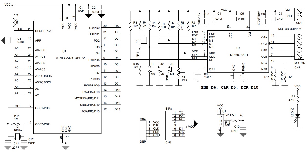
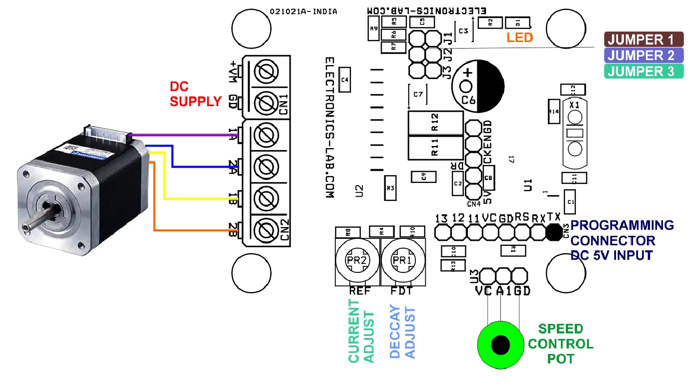
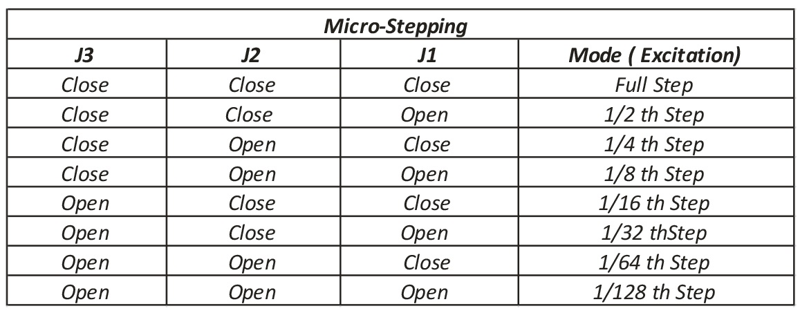
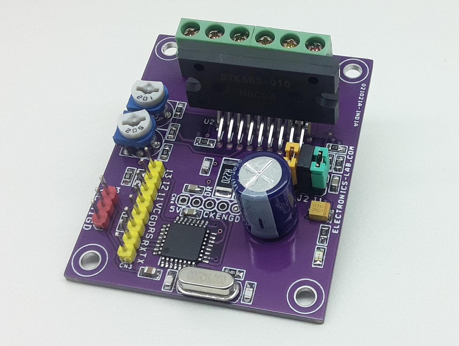
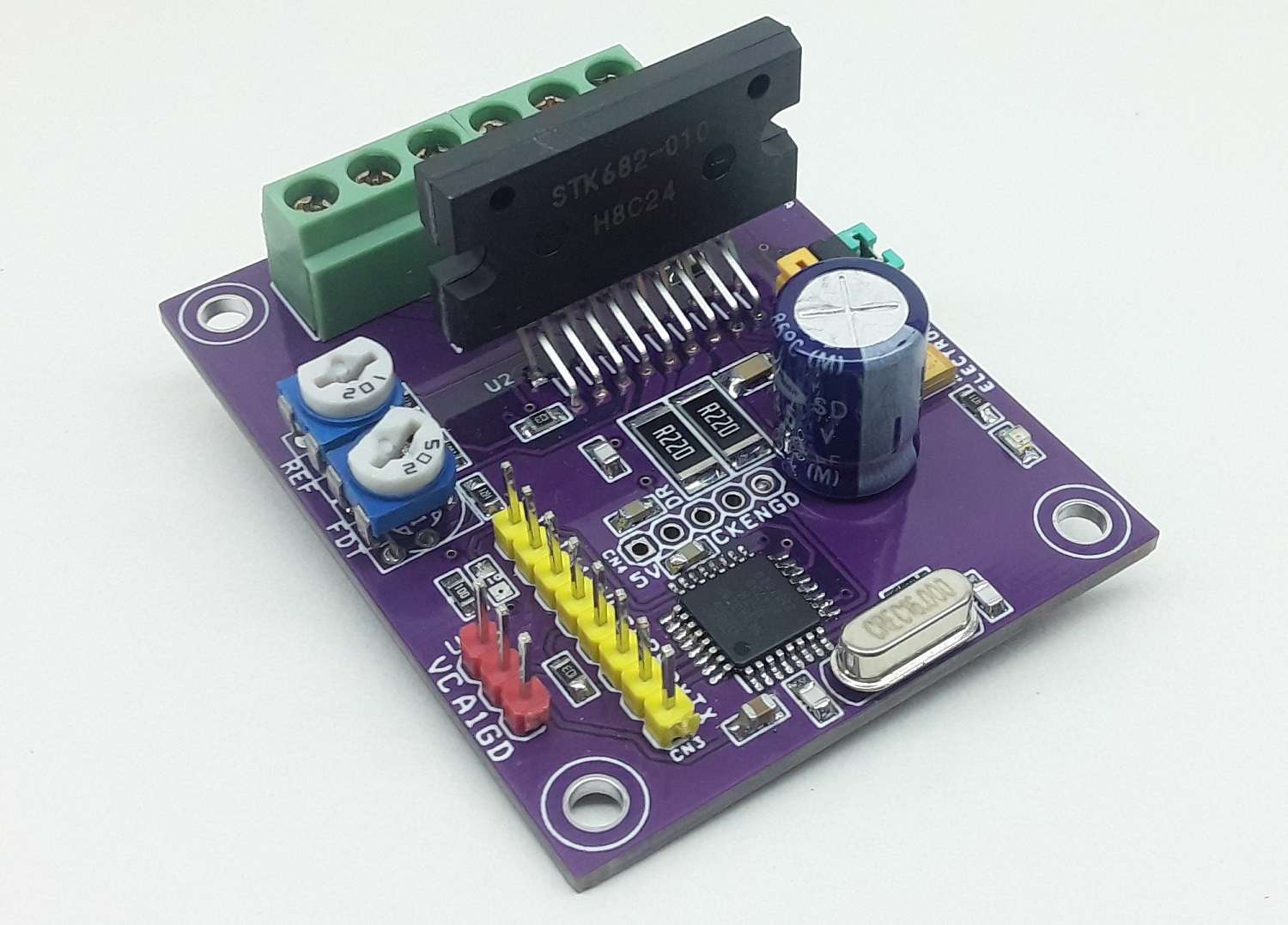
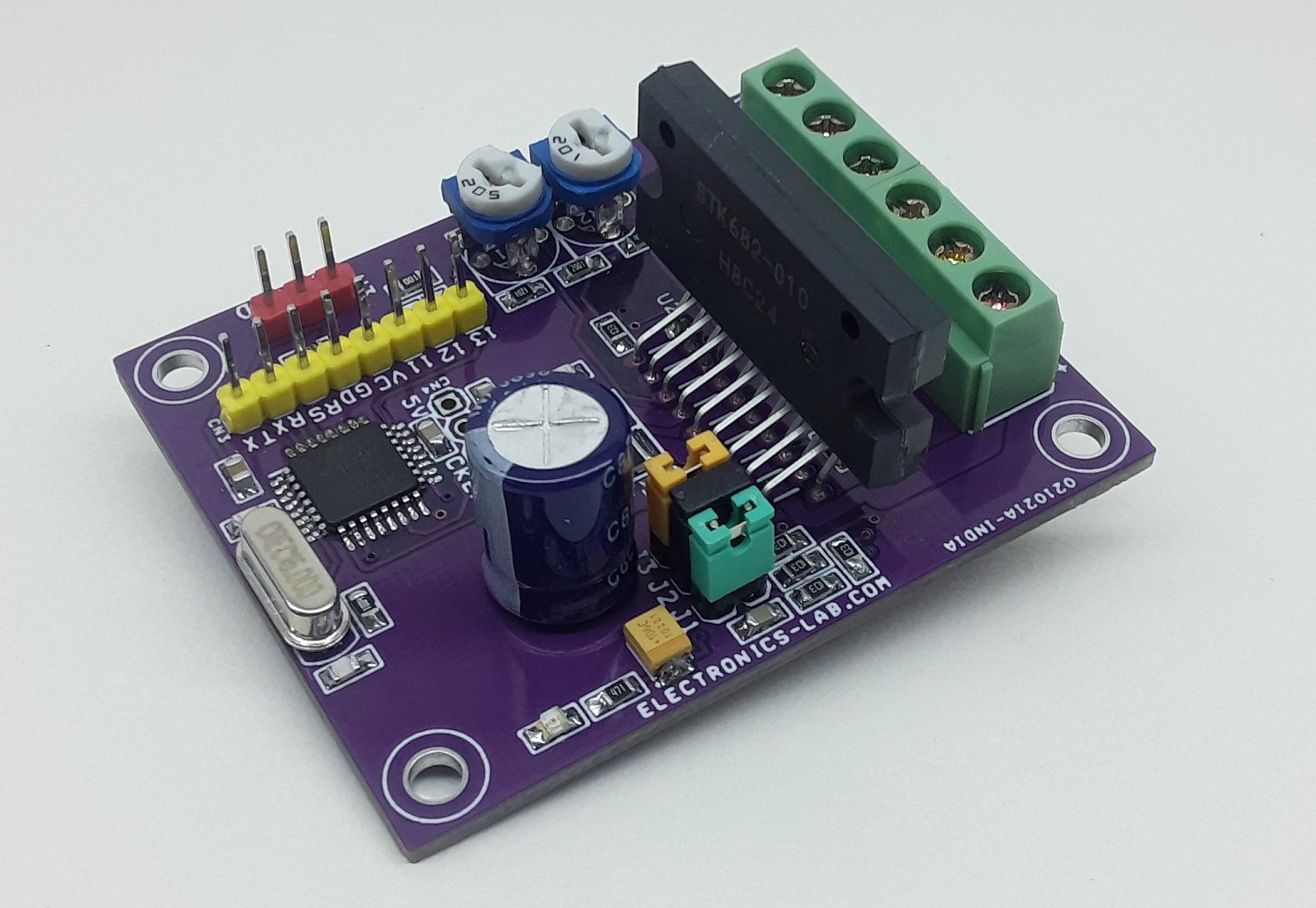
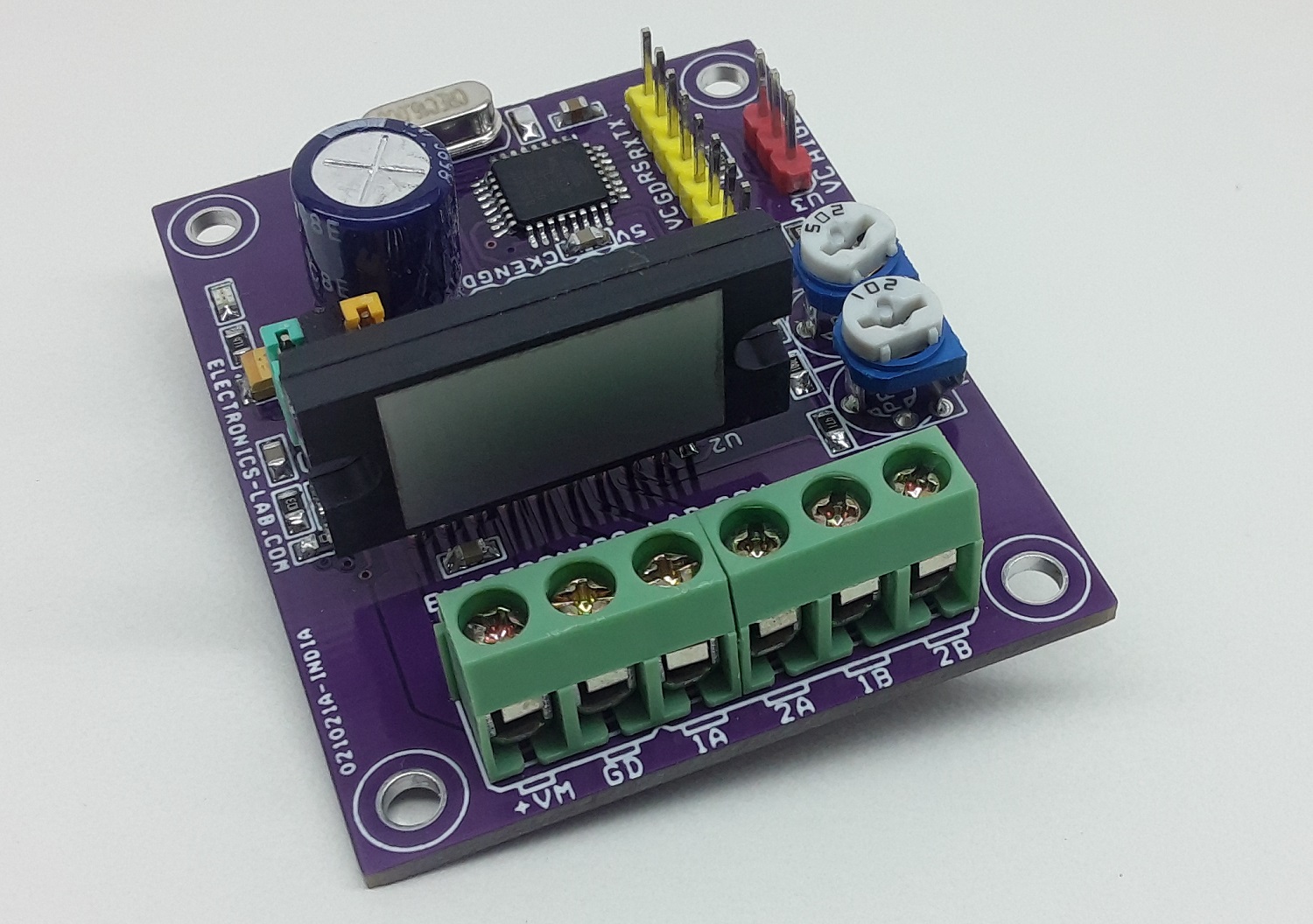
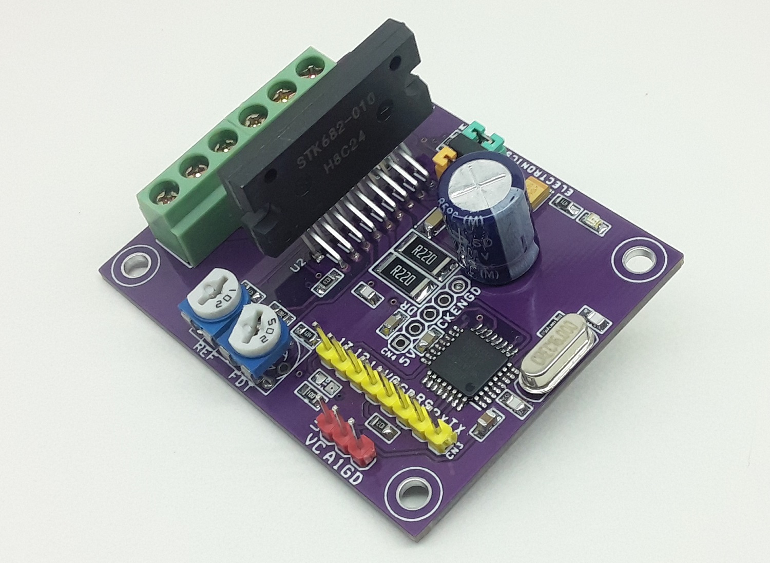
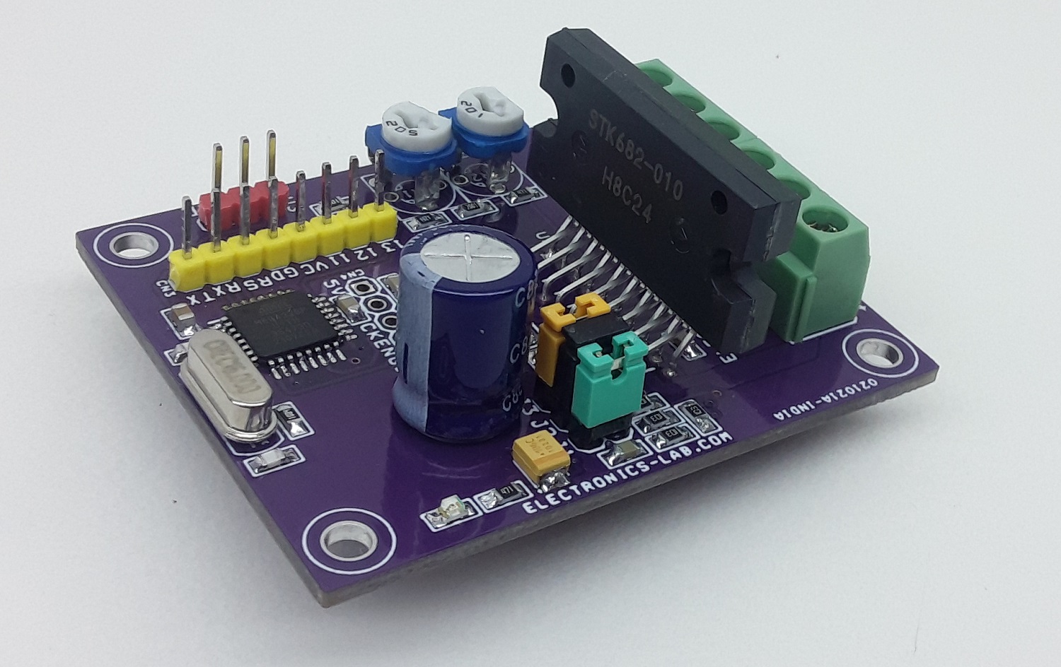
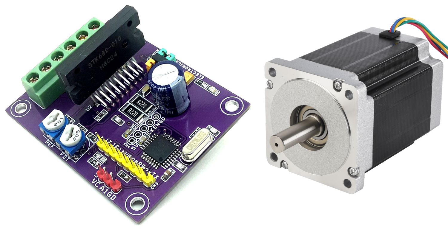
This is an Arduino compatible board that contains an Atmega328 microcontroller and Bipolar Stepper Motor Driver chip STK682-010. This Hybrid IC from ON Semiconductor can deliver up to 2.5A current and it can have an input supply up to 32V DC. It has multiple micro-stepping options such as Full step, 1/2th Step, 1/4th Step, 1/8th Step, 1/16th Step, 1/32th Step, 1/64th Step, 1/128th Step. PR1 trimmer potentiometer is provided to set the decay, 3.5V Slow Decay, 1.1V to 3.1V Mixed Decay, 0.8V-1V Fast Decay, and PR2 Trimmer Potentiometer provided to set the output current. Chopping frequency set to 83.3 Khz using capacitor C5 100PF. Micro-Stepping can be set with the help of jumper J1, J2, J3. This board is by default enabled since the enable pin has a pull-up resistor, but you can provide a low signal to disable the motor driver chip. Atmega328D provides Direction pulse, Step pulse, Enable control, etc. The IC has built-in automatic half current functions to reduce the vibrations & current while the motor is in static mode. It is important to use a heatsink on the motor driver chip. Refer to the micro-stepping table to set the micro-stepping. Board requires a Motor power supply as well logic supply 5Vdc.
Arduino Programming
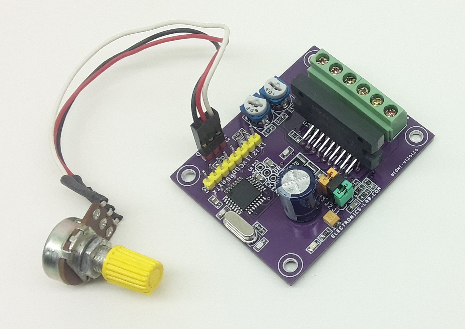
Arduino code is provided to test the board. The user will be able to control stepper motor speed using a 10K potentiometer connected to Analog pinA0 using connector U3. Users may write their own code to drive the motor as per requirements, micro-stepping is separate and independent from micro-controller. Only Pulse/Clock input, Direction, enable pins are connected to Arduino hardware.
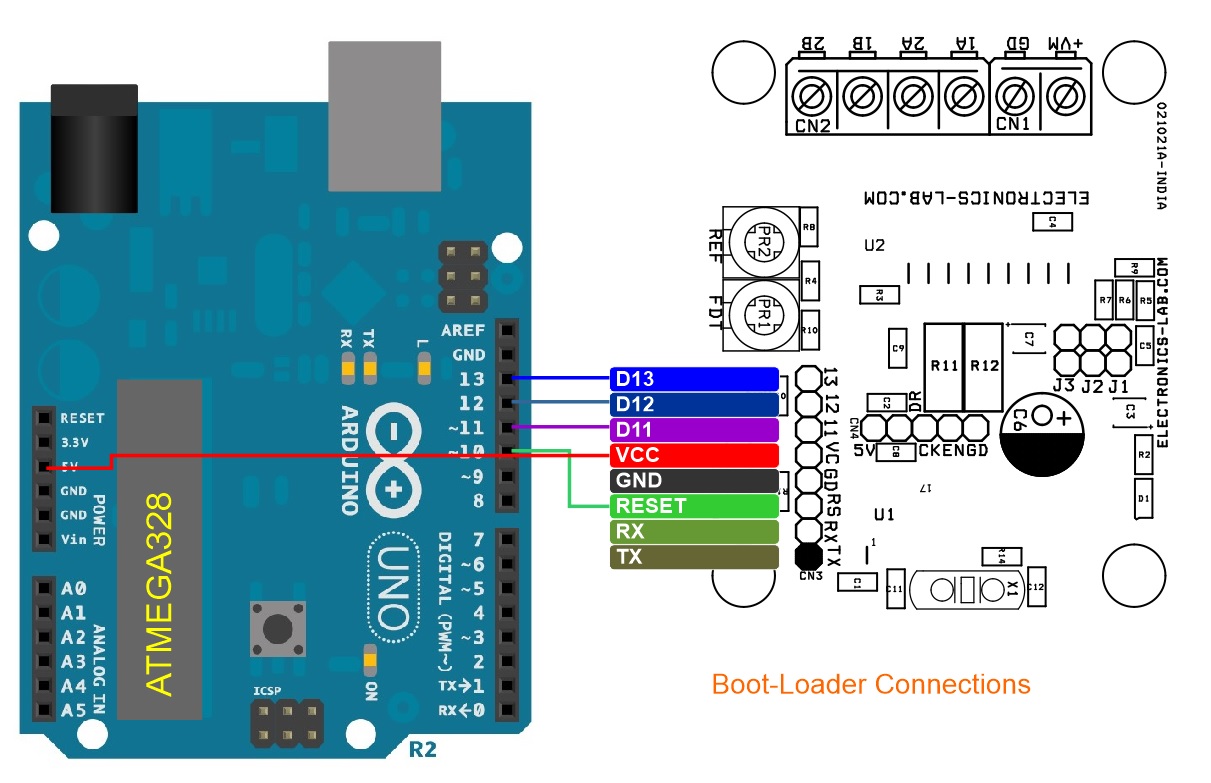
A new Atmega328 requires bootloader programming and Arduino code, refer to the link below for more information:
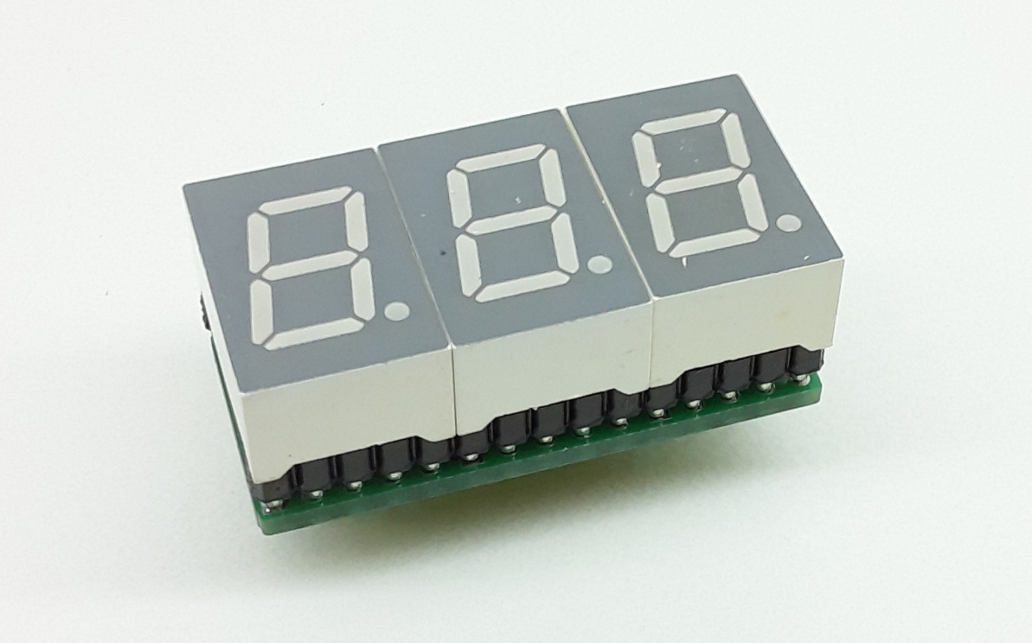
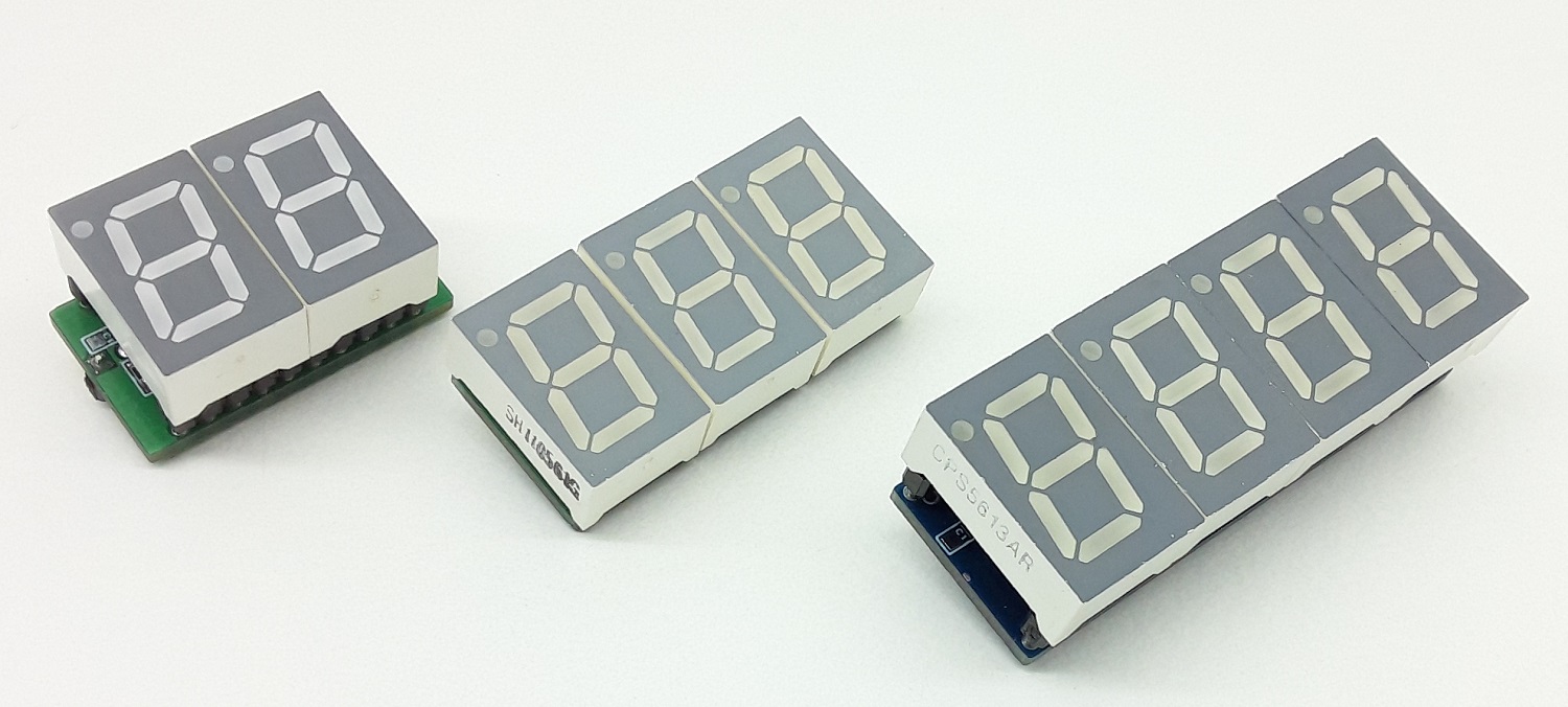
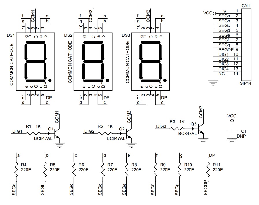
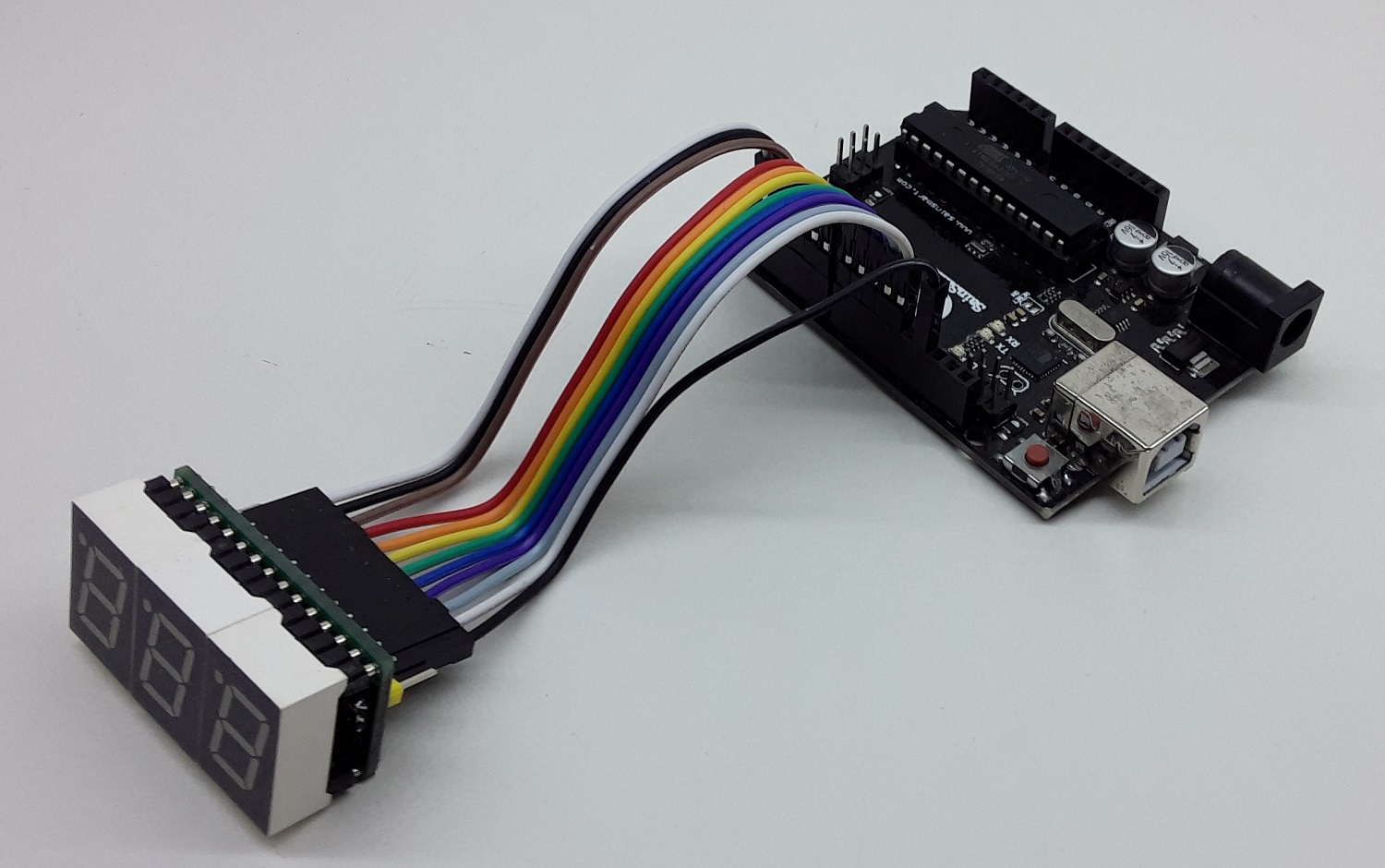
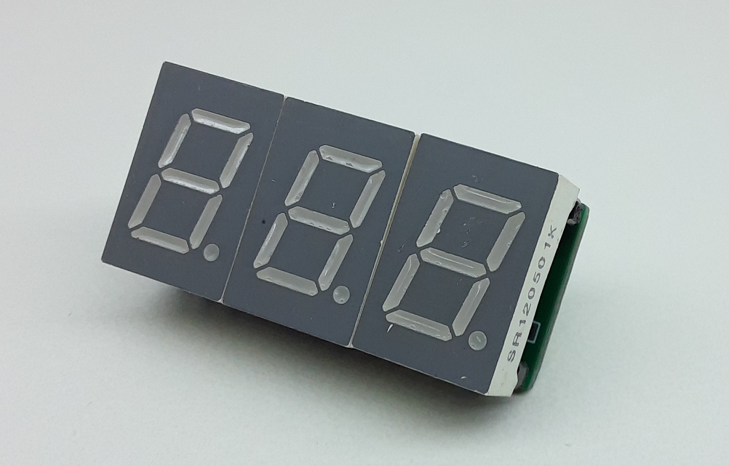
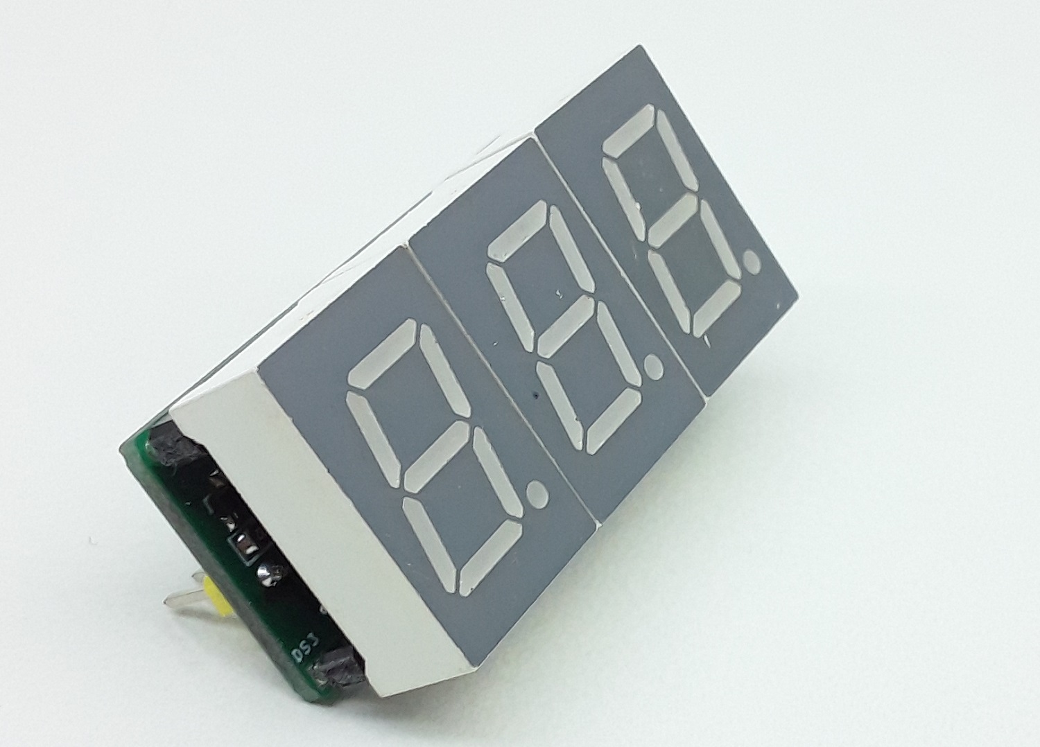
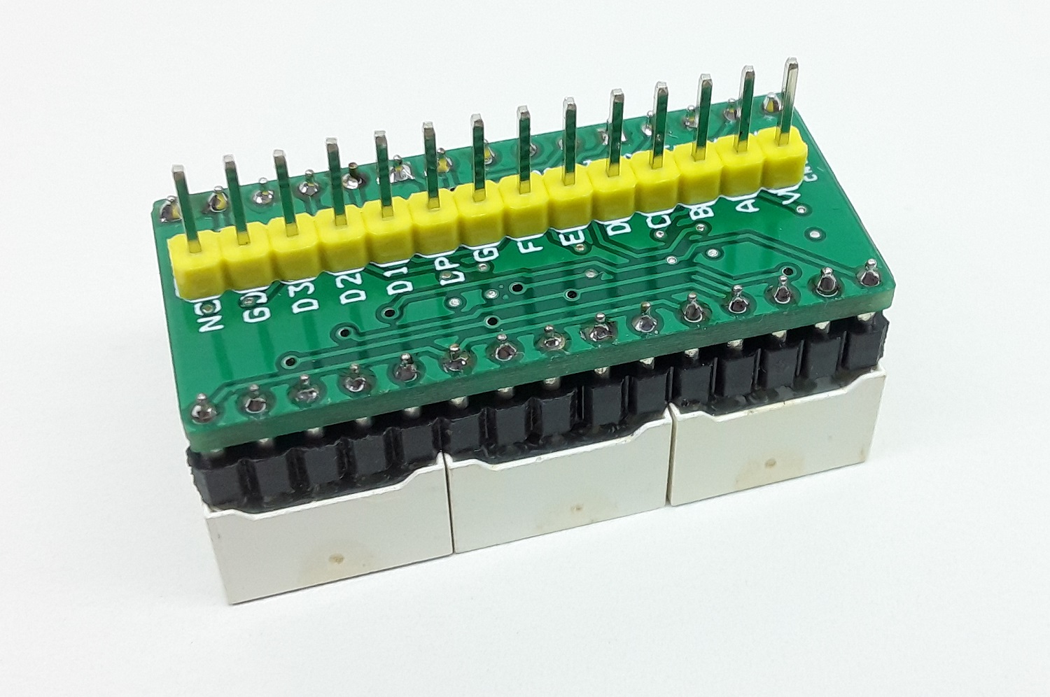
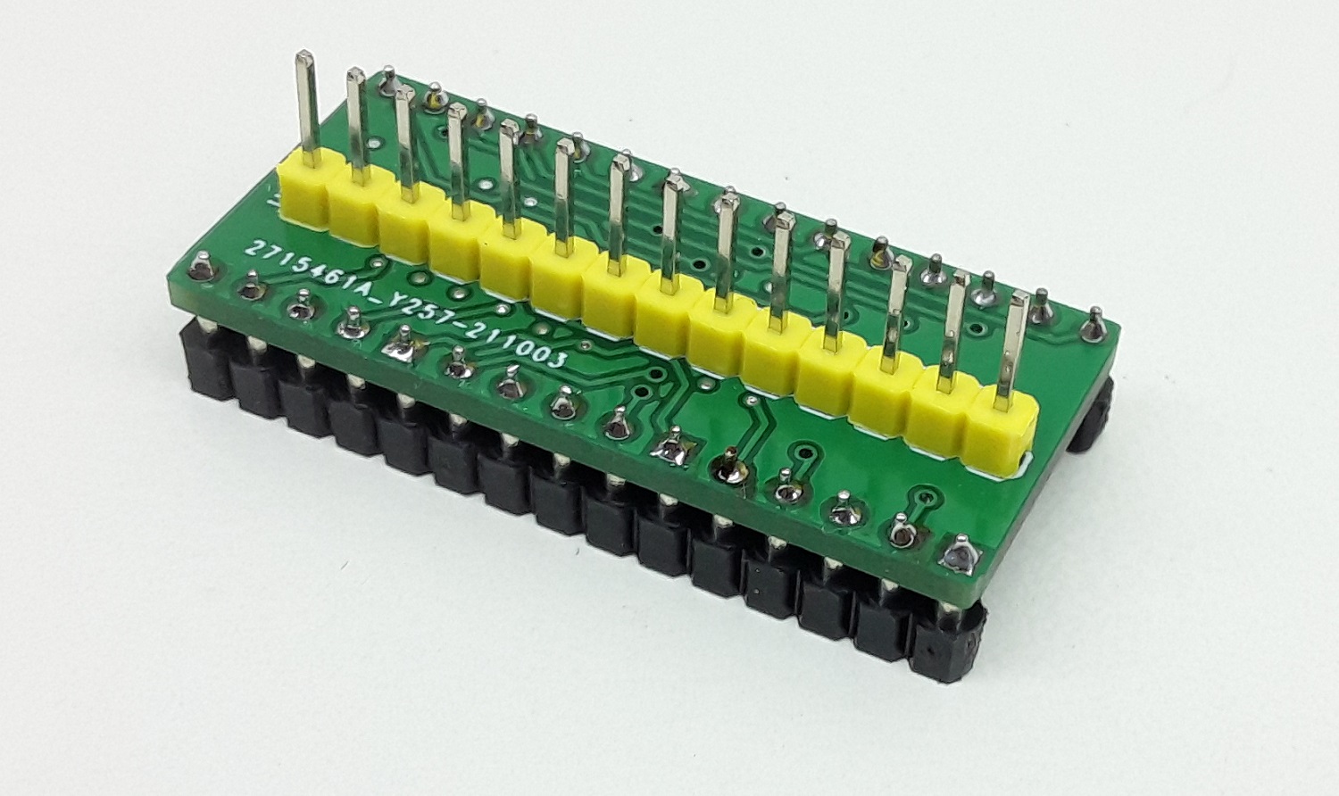
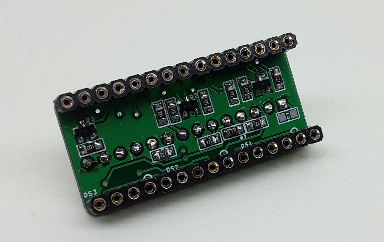
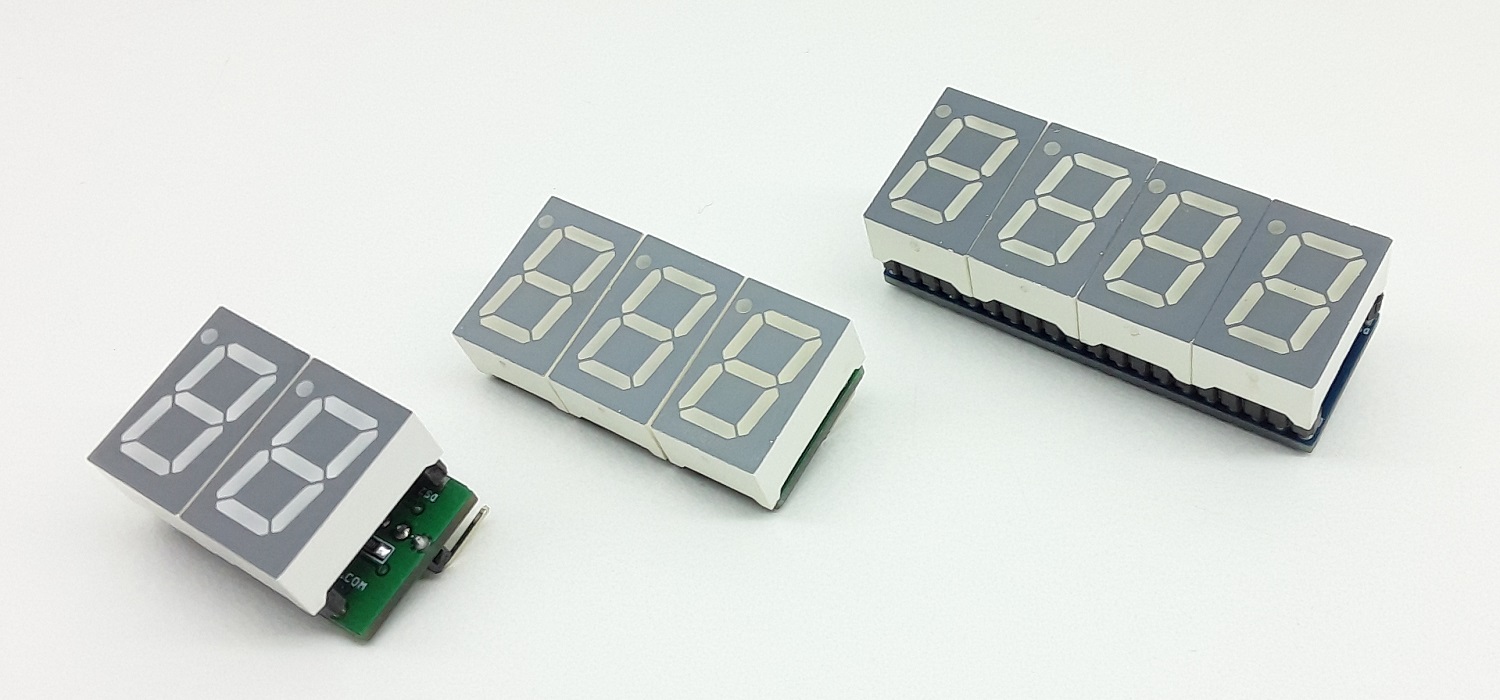
This is a 3 Digit 7-segment display project that contains 3 x Common Cathode displays, current limiting resistors or each LED segment, 3 x PNP Transistor on each common cathode for multiplexing etc. The project works with 5V TTL signals but can be optimized for 3.3V operations by reducing the current limiting resistors’ value. A header connector is provided for easy interface to Arduino or other microcontrollers. All inputs are TTL 5V compatible.
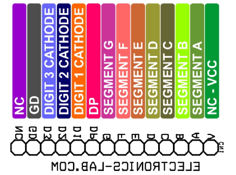
Arduino code is provided to test the board. The user will be able to create a 0 to 5V DC Voltmeter using this code. Upload the code to Arduino Uno, apply 0 to 5V to Analog Pin A0 to Measure the voltage. Refer Arduino pin configuration vs display bellow:
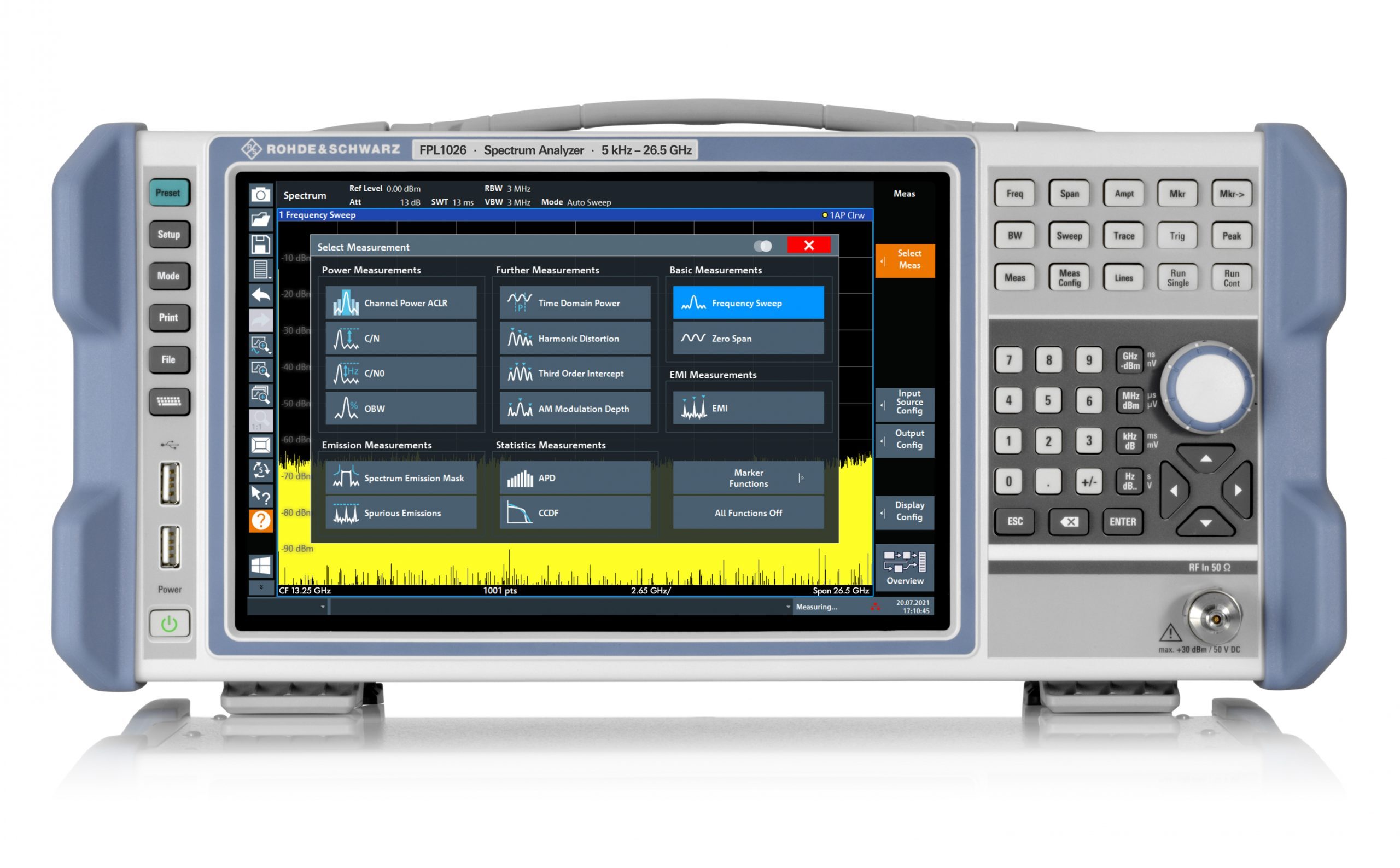
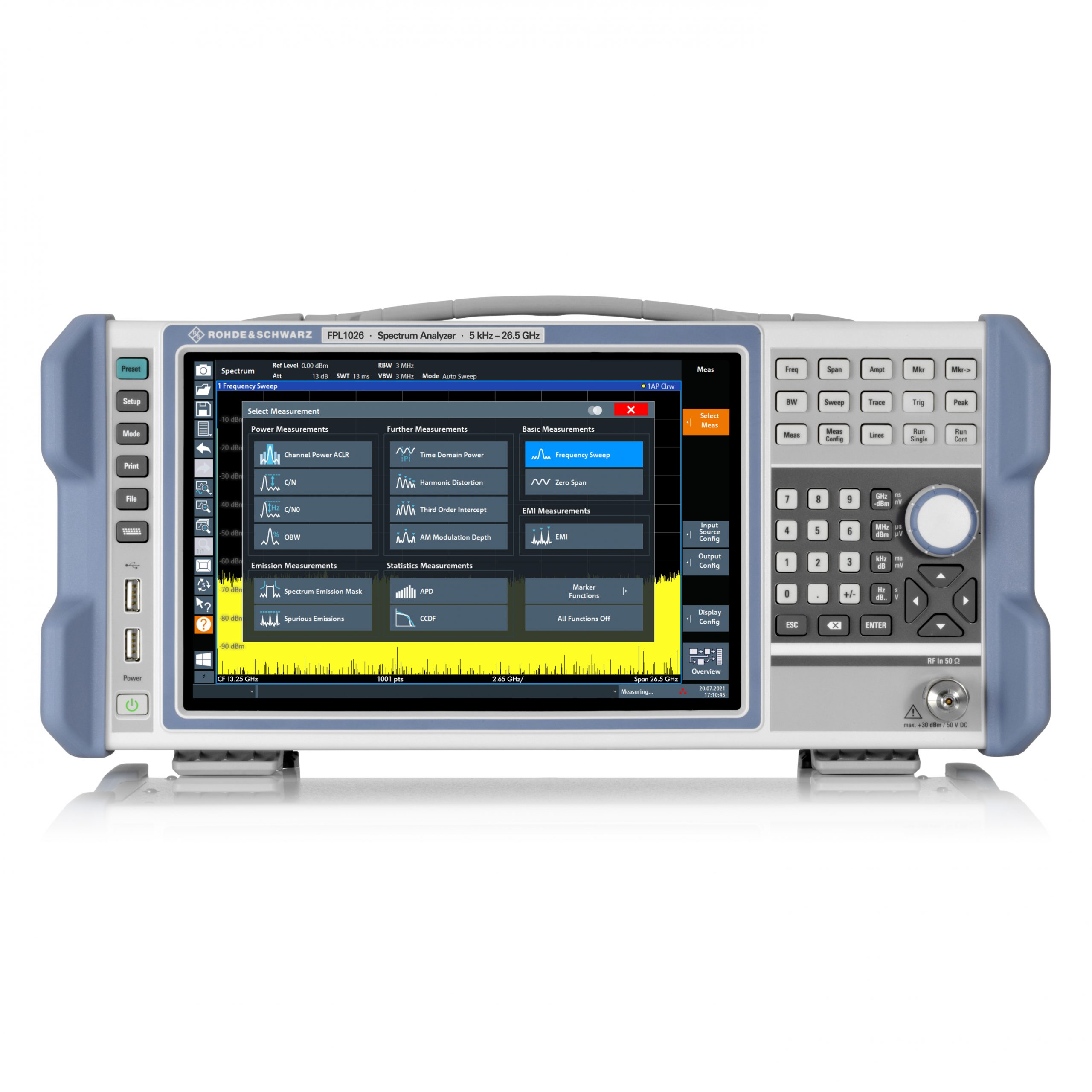
New base models for the portable R&S FPL1000 take spectrum and signal analysis capabilities up to 26.5 GHz. They combine the functionality of benchtop instruments and the portability of a handheld instrument, with intuitive features to make high-performance measuring on the go fast and simple.
The R&S FPL1000 spectrum analyzer combines the functionality of benchtop instruments and the portability of a handheld instrument.
Rohde & Schwarz has extended its popular R&S FPL1000 family with the introduction of new base models offering measurement frequencies up to 26.5 GHz. For the series, two new models have been added to the range, providing capabilities from 5 kHz to 14 GHz and 5 kHz to 26.5 GHz.
The R&S FPL1000 is a single measuring instrument for general purpose applications and various types of measurements. It can analyse signals with a bandwidth of 40 MHz, and it is the only instrument in its class with battery operation that features an internal generator up to 7.5 GHz. It is the go-anywhere instrument for spectral measurements, for highly accurate power measurements with power sensors and for analysing analogue and digitally modulated signals. Even in its basic configuration, the R&S FPL1000 is quick and intuitive for measurements including: spectrum analysis with measurement functions such as channel power, ACLR, signal-to-noise ratio, spurious, harmonic distortions, third-order intercept point, AM modulation depth. Capabilities extend further to include statistical ADP and CCDF analysis and versatile marker functions.
Measurement applications are also available for analysing analogue and digitally modulated signals. The R&S FPL1-K7 option turns the R&S FPL1000 into an analogue modulation analyzer for amplitude, frequency and phase-modulated signals. The base unit’s I/Q analyzer supports the magnitude and phase presentation of I and Q within the analysis bandwidth. The I/Q data can be exported for further analysis with third-party software products. The R&S FPL1-K54 provides EMI measurements for diagnostics of RF interference. The R&S FPL1-K70 vector signal analysis option also characterises digitally modulated single-carrier signals. There are additional options for multi-modulation analysis and measurement of BER on PRBS data.
The R&S FPL1000 family delivers solid RF performance: typical phase noise is -108 dBc at 10 kHz offset (1GHz carrier), together with displayed average noise level (DANL) of -163 dBm using the optional pre-amplifier. Performance, affordability, and ease-of-use make the R&S FPL1000 the ideal instrument for use in the lab, monitoring satellite ground stations, and communication links, education, test houses, in production, and in service facilities.
The R&S FPL1000 spectrum analyzers with new frequency ranges are part of the R&S Essentials portfolio. All models are now available from Rohde & Schwarz and selected distribution partners.
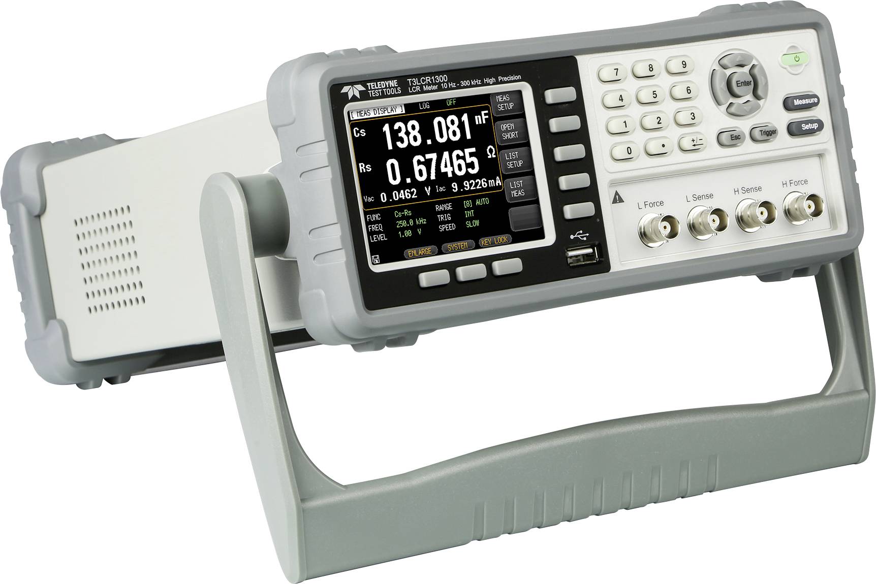
Teledyne LeCroy’s T3LCR series of high-precision LCR meters offers three models with a maximum test frequency ranging from 2 kHz to 300 kHz and basic accuracy of 0.05%. The T3LCR meters are compact and are equipped with diverse measurement functionalities, making them an excellent choice in meeting the requirements of R&D, component assessment for engineering departments, sorting, and quality control in production environments.
The T3LCR series provides a rich set of functionalities while maintaining a compact size. The entire series adopts a 3.5″ color LCD and features clearly displayed parameters. In addition to simultaneously displaying setting criteria and measurement results, the series also includes two additional monitoring parameters. The four parameters (primary + secondary and two monitoring) are simultaneously shown on the screen that enhances the measurement efficiency. The enlarged display mode not only emphasizes the measurement results but also provides PASS/FAIL results to facilitate a rapid and convenient validation process.
The T3LCR series also features a range of ancillary measurements to meet the measurement requirements of different materials. For instance, the T3LCR series provides the automatic level control (ALC) function to satisfy the test voltage requirement of MLCC devices. For inductive component measurements, the T3LCR series provides the adjustable test current function and the DC resistance measurement function. With respect to the DC bias voltage test for capacitive components requirements, the T3LCR series allows users to conduct verification measurements on materials by using its internal ±2.5V adjustable voltage. Furthermore, to observe the trend of the DUT characteristics, a list of up to 10 functional steps allows users to set testing parameters (either by frequency, voltage, or current) for each step, based on the user’s requirements.
The T3LCR meter’s list measurement feature can be used to perform automatic sweep measurements. The sweep measurements can be performed by listing up to 10 swept frequency or amplitude (voltage/current) points. Up to 10,000 measured readings can be saved to an internal buffer. These readings can then be exported to an external USB drive in a .csv file format.
For the external control, the T3LCR series comes equipped with a Handler interface, RS-232C, and USB interface. Handler outputs 10 BIN (9 BIN, AUX: 1 BIN) sorting results that are suitable for external control; for example, controlling a component sorting operation based on the measurement results obtained by the LCR meter. RS-232 and USB are suitable for remote control operation as well as to retrieve measurement results. Additionally, the free PC software gives users an instant tool to store measurement results.
Features
3.5″ color LCD
Continuous test frequency
Basic accuracy of 0.05%
Measuring speed: 25 ms (max)
Suitable for MLCC testing
Spot frequency or full frequency range OPEN/SHORT correction
16 major/secondary parameter measurement combinations and two additional monitoring parameters (maximum of four different parameters can be shown simultaneously)
DCR measurement and internal D.C. bias voltage (±2.5 V)
PASS/FAIL result
Auto level control (ALC) function
BIN function provides 10 BIN (9 BIN, AUX: 1 BIN)
List measurement feature to perform automated sweep measurements by listing up to 10 frequency or amplitude points
Standard interface: RS-232C, USB, Handler, and USB storage
Compact size, ideal for automatic equipment (2U, 1/2 rack)
An 11.6-inch Tianma TFT display module is in stock at distributor Review Display Systems (RDS).
The TM116VDSP02 features Full HD (1920 x 1080 pixels) resolution, a 16:9 wide aspect ratio, a high brightness rating, and exceptional optical performance characteristics.
Ideal for use in high ambient light and outdoor environments, the Tianma TM116VDSP02 is manufactured with an anti-glare surface polariser and supports 88° wide viewing angles in all directions (up/down, left/right).
Supporting a brightness specification of 1600cd/m² and a contrast ratio of 900:1, display images are bright, colorful, and concise. The white LED backlight has a 50K hour half brightness lifetime.
Typical applications include graphical user interfaces (GUI) for ticketing systems, information terminals, point-of-sale equipment, marine navigation, and in-vehicle systems.
“The high brightness Tianma 11.6-inch TFT display module provides a versatile and highly capable display solution for a wide range display applications particularly those where high levels of ambient or outdoor light may be present. Additionally, RDS can offer advice, design-in support and expertise for customers developing display-based products for a wide range of applications and equipment.”
The 11.6inch display module has mechanical outline dimensions of 273.5mm (w) x 166.5mm (h) x 7.8mm (d) and an active display area of 256.3mm (w) x 144.2mm (h).
A wide operating temperature range of -20°C to +80°C enables operation in extreme operating environments.
The 30-pin data interface supports dual-channel 24-bit LVDS and 8-bit RGB color data enabling a color palette of up to 16.7m colors.
Review Display Systems have extensive experience and knowledge designing and developing fully integrated embedded systems utilizing the latest display and embedded computing technology.
The 11.6-inch Tianma TM116VDSP02 TFT display module is now available immediately from Review Display Systems.
Representing leading global manufacturers, RDS supports a comprehensive range of display technologies, touch screen,s and embedded computing solutions.
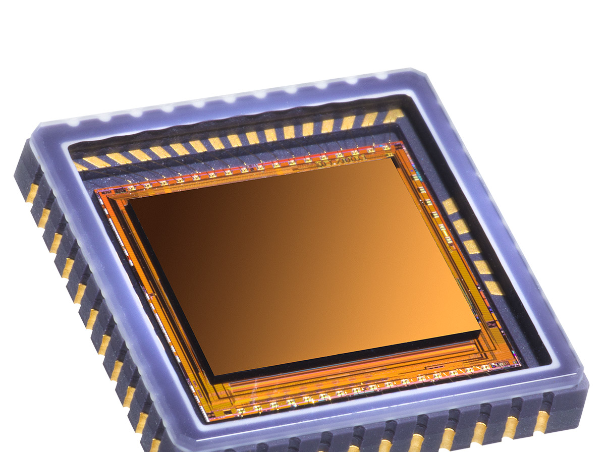
Lynred has announced enhanced capabilities across the range of its 12µm infrared detectors, to enable optronic systems to more accurately identify objects in low-contrast scenes.
These 12 µm pixel pitch infrared detectors, based on a microbolometer technology, come with enhanced thermal sensitivity, permitting use in limitless applications.
Applications include integration into outdoor leisure equipment for use at dawn or at night.
Lynred’s range of 12 µm microbolometers is suitable for enabling optronics systems to deliver the image quality end-users seek to observe nature in early forest mist and in all-weather conditions.
“Lynred is proud to have increased the maturity and strength of its entire range of 12µm thermal imaging microbolometers,” said Jean-Yves Dussaud, Chief Marketing Officer at Lynred.
“These higher sensitivity advancements enable us to better respond to the diversified needs in new markets.”
The 12µm pixel pitch microbolometer is the emerging standard for producing smaller thermal cameras that use space-saving optics. NETD (noise equivalent temperature difference) is one of several key parameters used to evaluate the image quality of optronics systems and thermal cameras. With Lynred’s 12µm products, customers will benefit from gains in the performance of their NETD lower than 40 or 50mK, depending on the product grade, and other performance criteria: scene dynamics and mechanical robustness.
Range of 12 µm products
Atto320-02: a compact and low-power consumption 320×240 digital 12µm microbolometer offering fluid and crisp images – available Q1 2022
Atto640-02: a compact, low power 640×480 12µm microbolometer (in analogue and digital formats) for SWaP (size, weight and low-power) applications, offering fluid and crisp images – available end 2021
Atto1280-02: a robust and compact 1280×1024 12µm microbolometer, offering long range detection and high-quality wide field of view images; it has the smallest packaging footprint in its category – available Q1 2022
Lynred’s microbolometer technology portfolio
Lynred has within its technology portfolio several compound semiconductor materials. It decides which device to develop and manufacture based on the merits of the material that best suits and meets the needs of a target application. The materials Lynred uses to develop microbolometers includes a-Si (amorphous silicon), the principal material underpinning the company’s 17µm microbolometer; this product line has had a long and successful track record among international clients in a cross-section of markets: leisure, security & surveillance, defense and thermography.
Other materials include Vox, a supplementary technology Lynred developed with the support of CEA-Leti, a high-tech research institute pioneering micro- and nanotechnologies, for integration in the 12-micron IR detector product family. It was introduced to provide the most adapted offer to the optronics needs of clients, with a view to having the same performance while reducing pixel size.