Variscite and Hailo Partner to Provide Out-of-the-Box, Full-Scale, Edge AI Solutions

Variscite’s i.MX 8 System on Modules, combined with Hailo’s Mini PCIe AI module, enables enterprises to run full-scale deep learning (DL)-based applications more efficiently and sustainably while significantly lowering costs

Variscite, a leading global provider of trusted Systems on Module (SoM) solutions for the embedded market, today announced its partnership with leading AI (Artificial Intelligence) chipmaker Hailo to launch a ready-to-use reference platform enabling high-performance and scalable AI capabilities at the edge.

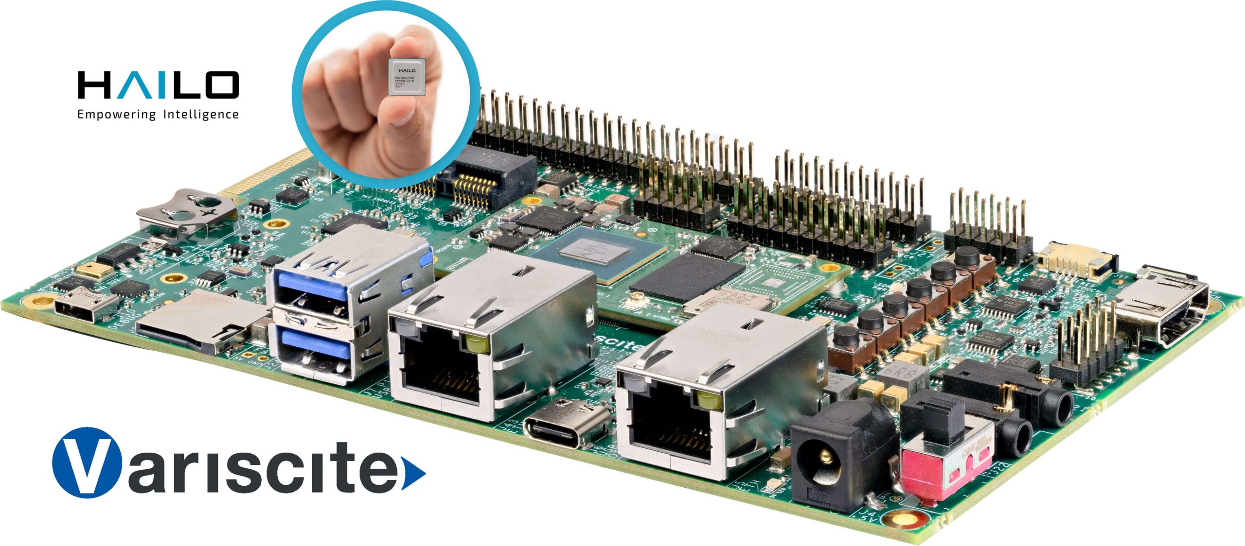
The joint, complete edge AI solution will combine Variscite’s i.MX 8 platforms with Hailo’s Mini PCIe AI module to enable enterprises to run full-scale deep learning (DL)-based applications more efficiently and sustainably while significantly lowering their costs.

Variscite’s DART-MX8M-PLUS and VAR-SOM-MX8M-PLUS are based on NXP’s i.MX 8M Plus SoC with integrated AI capabilities up to 2.3 tera-operations per second (TOPS). These products, combined with the Hailo-8TM AI processor , which provides up to 26 TOPS and significantly outperforms other AI edge processors in the market, deliver high-performance, scalable edge AI solutions for industries including Industry 4.0, smart cities, smart retail, automotive and more. Moreover, Hailo’s AI accelerator modules can be mounted on additional Variscite SoM platforms, including processors from the i.MX 8 series that have no integrated AI engine, such as the i.MX 8M and i.MX 8M Mini.

“Our joint partnership with leading AI company such as Hailo allows us to expand access to AI and deep learning at the edge to a wider range of customers and applications, while upgrading our product offering with a higher-performance solution”, said Ofer Austerlitz, VP Business Development and Sales at Variscite.”We are excited to offer our customers advanced AI at the edge solutions, enabling them to power applications across the various industries they are in with a more scalable and higher performance solution”.

Variscite’s System on Modules, integrated with the Hailo’s mPCIe AI module and with the compatible Basler camera,  delivers 30 Frames Per Second (FPS) while running YOLOv5m in Full High Definition (FHD) resolution with minimal power consumption.

“Our partnership with leading SoM vendor Variscite brings the performance capabilities of customers’ edge devices to a new level”, said Liran Bar, VP Business Development of Hailo. “This joint solution significantly boosts the AI capabilities for anyone using Variscite’s System on Modules, enabling a broader range of deep learning-based applications in industries across the board. We look forward to continuing our collaboration with Variscite to help bolster the power of edge devices everywhere.”

The Hailo-8™ Mini PCIe AI acceleration module is fully integrated with Variscite’s i.MX 8 platforms, providing customers with state-of-the-art AI capabilities integrated directly into their connected edge devices.

Arduino 4-Digit 0.5″ Common Cathode 7 Segment Display Module

This project will help you to easily develop an Arduino compatible project that requires 4 x -7Segment 0.5″ displays. The project consists of an Atmega328 microcontroller, 4 x BC847 NPN transistors to drive the common cathode displays. All displays are used in multiplexing configurations. The circuit operates with 5V DC and consumes a few milliamps. Arduino code is provided to test the board. The code is pretty simple, it will read 0 to 5V on analog pin A0 and display 0 to 1000 display, basically 0 to 5V mapping to 0-1000. Users may write their own code to read an analog voltage from a sensor or other source and display it on the 4 x 7segment displays.

The new Atmega328 chip requires a bootloader and Arduino firmware, follow the link below to learn more about programming and bootloader burning.

https://www.arduino.cc/en/Tutorial/BuiltInExamples/ArduinoToBreadboard

Arduino Compatible Hardware Contains

  • Atmega328 microcontroller
  • 4 Digit 0.5″ 7 Segment Display, Common Cathode
  • 4 x BC847 Transistors to drive Display Common Cathode for Multiplexing
  • CN1: Arduino Programming and Boot-Loader
  • CN1: 3 Pin Connector to Connect LM35 Temperature Sensor or Analog Input
  • Current Limiting Resistors for 7 segment display and other components

Applications

  • 4 Digit Counter
  • 4 Digit Thermometer
  • Voltmeter
  • Current Meter
  • Sensor Value Display- Analog Voltage Reading
  • 4 Digit Score Board
  • Gaming

Features

  • Supply 5V DC, can be optimized for 3.3V Operations
  • LM35 Temperature Sensor or Analog Input A0
  • Compact Hardware
  • PCB Dimensions 51.28 x 34.93 mm

Arduino Pins

  • Digital Pin D10 Display 1 Common Cathode
  • Digital Pin D11 Display 2 Common Cathode
  • Digital Pin D12 Display 3 Common Cathode
  • Digital Pin D13 Display 4 Common Cathode
  • Digital Pin D2 Display Segment A
  • Digital Pin D3 Display Segment B
  • Digital Pin D4 Display Segment C
  • Digital Pin D5 Display Segment D
  • Digital Pin D6 Display Segment E
  • Digital Pin D7 Display Segment F
  • Digital Pin D8 Display Segment G
  • Digital Pin D9 Display Segment DP
  • Analog Pin A0 Analog Input from Sensor, LM35 Temperature Sensor

Similar Modules

Schematic

Parts List

NOQNTY.REF.DESCMANUFACTURERSUPPLIERPART NO
11CN13 PIN MALE HEADER PITCH 2.54MMWURTHDIGIKEY732-5316-ND
22C1,C40.1uF/50V SMD SIZE 0805MURATA/YAGEODIGIKEY
32C2,C322PF/50V SMD SIZE 0805MURATA/YAGEODIGIKEY
42C5,R17DNP
54DS1,DS2,DS3,DS40.5/0.56INCH 7 SEGMENT DISPLAY COMMON CATHODELUMEX OPTODIGIKEY
61D1LED SMD SIZE 0805LITE ON INCDIGIKEY160-1427-1-ND
74Q1,Q2,Q3,Q4BC847ALNEXPERIADIGIKEY1727-2924-2-ND
85R1,R4,R5,R6,R71K 5% SMD SIZE 0805MURATA/YAGEODIGIKEY
91R210K 5% SMD SIZE 0805MURATA/YAGEODIGIKEY
101R31M 5% SMD SIZE 0805MURATA/YAGEODIGIKEY
118R8 To R15220E 5% SMD SIZE 0805MURATA/YAGEODIGIKEY
121R1610E 5% SMD SIZE 0805MURATA/YAGEODIGIKEY
131U1ATMEGA328 DIP 28MICROCHIPDIGIKEYATMEGA328-PU-ND
141Y116MHZECS INCDIGIKEYX1103-ND
151CN22 PIN MALE HEADER PITCH 2.54MMWURTHDIGIKEY732-5315-ND
161SCKT28 PIN DIP IC SOCKETON SHORE TECHDIGIKEYED3050-5-ND

Connections

Gerber View

Photos

Video

SC56-21SRWA Datasheet

Arduino 3-Digit 0.5″ Common Cathode 7 Segment Display Module

This project will help you to easily develop an Arduino compatible project that requires 3 x 7-Segment 0.5″ displays. These are common cathode displays that use multiplexed configuration, BC847 transistor drives 3 x common cathodes, all display segments are connected to the microcontroller using current limiting resistors. The circuit operates with 5V DC, Connector CN1 is provided for bootloader and Arduino firmware upload. Upload Arduino code to test the board. The user will be able to create a 5.00V Voltage Meter. Use analog pin A0 for voltage input, Connector U2.

Arduino Programming

A new Atmega328 chip requires a bootloader and Arduino firmware upload. Connector CN1 is provided for both operations, follow the link below to learn more about programming the board using Arduino.

https://www.arduino.cc/en/Tutorial/BuiltInExamples/ArduinoToBreadboard

Arduino Compatible Hardware

  • Atmega328 microcontroller
  • 3 x Digit 0.5 Inch 7 Segment Display, Common Cathode
  • 3 x BC847 Transistors to drive Display Common Cathode for Multiplexing
  • CN1: Arduino Programming and Boot-Loader
  • U2: 3 Pin Connector to Connect LM35 Temperature Sensor or Analog Input
  • Current Limiting Resistors for 7 segment display and other components

Applications

  • 3 Digit Counter
  • 3 Digit Timer
  • 3 Digit Thermometer
  • Voltmeter
  • Current Meter
  • Sensor Value Display
  • 3 Digit Score Board
  • Dice

Features

  • Supply 5V DC can be optimized for 3.3V Operations
  • LM35 Temperature Sensor or Analog Input A0
  • Compact Hardware
  • PCB Dimensions 38.42 x 35.40 mm

Arduino Pins

  • Digital Pin D10 Display 1 Common Cathode
  • Digital Pin D11 Display 2 Common Cathode
  • Digital Pin D12 Display 3 Common Cathode
  • Digital Pin D2 Display Segment A
  • Digital Pin D3 Display Segment B
  • Digital Pin D4 Display Segment C
  • Digital Pin D5 Display Segment D
  • Digital Pin D6 Display Segment E
  • Digital Pin D7 Display Segment F
  • Digital Pin D8 Display Segment G
  • Digital Pin D9 Display Segment DP
  • Digital Inputs D13, D12, D11, TX, RX (Available for Inputs after programming)
  • Analog A0 for Analog Signal Input from Sensor or Analog Source
  • Programming and Boot-loader Pin D13, D12, D11, TX, RX, RESET

Similar modules

Schematic

Parts List

NOQNTY.REFDESCMANUFACTURERSUPPLIERPART NO
11CN18 PIN MALE HEADER PITCH 2.54MMWURTHDIGIKEY732-5321-ND
21C110uF/10V SMD SIZE 0805MURATA/YAGEODIGIKEY
32C2,C30.1uF/50V SMD SIZE 0805MURATA/YAGEODIGIKEY
42R3,C4DNPMURATA/YAGEODIGIKEY
52C5,C622PF/50V SMD SIZE 0805MURATA/YAGEODIGIKEY
63DS1,DS2,DS30.5/0.56 INCH 7 SEGMENT COMMON CATHODE DISPLAYSUN LEDDIGIKEY754-1705-5-ND or 754-1704-5-ND
73Q1,Q2,Q3BC847ALNEXPERIADIGIKEY1727-2924-2-ND
81R110K 5% SMD SIZE 0805MURATA/YAGEODIGIKEY
91R210E 5% SMD SIZE 0805MURATA/YAGEODIGIKEY
103R4,R5,R61K 5% SMD SIZE 0805MURATA/YAGEODIGIKEY
118R7-R14220E 5% SMD SIZE 0805MURATA/YAGEODIGIKEY
121R151M 5% SMD SIZE 0805MURATA/YAGEODIGIKEY
131U1ATMEGA328TQPF-32MICROCHIPDIGIKEYATMEGA328PB-AURCT-ND
141U23 PIN MALE OR FEMALE HEADER OPTIONAL
151X116MhzECS INCDIGIKEYX1103-ND

Connections

Gerber View

Photos

Video

SC56-21SRWA Datasheet

Arduino 2-Digit 0.5″ Common Cathode 7 Segment Display Module

This is an Arduino compatible board for creating 2 Digit Display projects. The circuit operates with 5V DC, Connector CN1 is provided for bootloader programming and Arduino firmware upload. A new Atmega328 chip requires a bootloader and Arduino firmware programming, Connector CN1 helps you with both functions. Follow the link below to learn more about programming using Arduino. Arduino code is available as a download to test the board.

Arduino Programming

From Arduino to a Microcontroller on a Breadboard: https://www.arduino.cc/en/Tutorial/BuiltInExamples/ArduinoToBreadboard

Arduino Compatible Hardware

  • Atmega328 microcontroller
  • 2 Digit 0.5 Inch 7 Segment Display, Common Cathode
  • 2 x BC847 Transistors to drive Display Common Cathode for Multiplexing
  • CN1: Arduino Programming and Boot-Loader Connector
  • U2: 3 Pin Connector to Connect LM35 Temperature Sensor or Analog Input
  • Current Limiting Resistors for 7 segment display and other components

Applications

  • 2 Digit Counter
  • 2 Digit Timer
  • 2 Digit Thermometer
  • Voltmeter
  • Current Meter
  • Sensor Value Display
  • 2 Digit Score
  • Digital Dice

Arduino Pins

  • Digital Pin D10 Display 1 Common Cathode
  • Digital Pin D11 Display 2 Common Cathode
  • Digital Pin D2 Display Segment A
  • Digital Pin D3 Display Segment B
  • Digital Pin D4 Display Segment C
  • Digital Pin D5 Display Segment D
  • Digital Pin D6 Display Segment E
  • Digital Pin D7 Display Segment F
  • Digital Pin D8 Display Segment G
  • Digital Pin D9 Display Segment DP
  • DIGITAL INPUTS D13, D12, D11, TX, RX
  • ANALOG PIN A0 LM35 TEMPERATURE SENSOR OR ANALOG INPUT
  • PROGRAMING D13, D12, D11, TX, RX, RESET

Features

  • Supply 5V DC can be optimized for 3.3V Operations
  • LM35 Temperature Sensor, Analog Input A0
  • Compact Hardware
  • PCB Dimensions 37.78  x 26.04 mm

Similar modules

Schematic

Parts List

NOQNTY.REF.DESC.MANUFACTURERSUPPLIERPART NO
11CN18 PIN MALE HEADER PITCH 2.54MMWURTH732-5321-ND
21C110uF/10V SMD SIZE 0805MURATA/YAGEO
32C2,C30.1uF/50V SMD SIZE 0805MURATA/YAGEO
42R3,C4DNP
52C5,C622PF/50V SMD SIZE 0805MURATA/YAGEO
61DS17SEG-COMMON CATHODE 0.5INCHSUNLED754-1705-5-ND or 754-1704-5-ND
71DS27SEG-COMMON CATHODE 0.5INCHSUNLED754-1705-5-ND or 754-1704-5-ND
82Q1,Q2BC847ALNEXPERIA1727-2924-2-ND
91R110K 5% SMD SIZE 0805MURATA/YAGEO
101R210E 5% SMD SIZE 0805MURATA/YAGEO
112R4,R51K 5% SMD SIZE 0805MURATA/YAGEO
121R61M 5% SMD SIZE 0805MURATA/YAGEO
138R7 - R14220E 5% SMD SIZE 0805MURATA/YAGEO
141U1ATMEGA328TQPF-32MICROCHIPATMEGA328PB-AURCT-ND
151U23 PIN MALE OR FEMALE HEADER PITCH 2.54MMDNP
161X116MhzECS INCX1103-ND

Connections

Gerber View

Photos

Video

SC56-21SRWA Datasheet

PICO-EHL4: Flexible Embedded Edge Computing from AAEON

AAEON, an industry leader in embedded solutions, announces the latest addition to its lineup of compact PICO-ITX boards, the PICO-EHL4. Featuring the latest Intel® Atom™, Celeron® and Pentium® processors (formerly Elkhart Lake). With the combination of performance, flexibility and expansion features, the PICO-EHL4 provided developers with a capable solution for any project.

The PICO-EHL4 builds upon previous generations by delivering higher performance processors, faster memory speeds, and support for the latest computing technologies. This is thanks to utilizing the latest generation Intel® Atom™ x6000E series processors, Intel Pentium® and Celeron® N and J series processors (formerly Elkhart Lake). The PICO-EHL4 takes advantage of the support for faster memory speeds and higher capacities by providing up to 16GB of LPDDR4x 3200MHz memory on-board. The PICO-EHL4 also leverages support for in-band ECC with select processors, ensuring data integrity, an important feature for edge computing applications.

The PICO-EHL4 provides a host of features allowing for flexibility to meet the needs of individual applications. Expansion slots include both M.2 2230, perfect for adding Wi-Fi or Bluetooth functionality; and full sized Mini-Card for expanded storage, AI accelerators, and more. The PICO-EHL4 can connect with a range of devices thanks to 4-bit GPIO as well as dual Gigabit Ethernet LAN ports, two USB3.2 and two USB2.0 ports, and two serial port headers (RS232/422/485). The PICO-EHL4 also features two HDMI 2.0 ports supporting 4K graphics at 60Hz, as well as on-board co-lay LVDS/eDP allowing the board to output up to three independent displays.

“The PICO-EHL4 delivers greater performance and flexibility than previous generations, at a cost that is comparable, making it a great choice for new projects or upgrading existing deployments without going over budget,” said Ariel Long, Product Manager with AAEON’s Embedded Computing Division. “Developers can easily deploy the board to a range of applications including AI edge computing, compact PC controller, kiosks and more.”

The PICO-EHL4 is backed by AAEON’s expertise in building compact, rugged solutions designed to operate in a wide range of industrial and other environments. AAEON also offers a range of manufacturer and OEM/ODM services, from customizing board layouts to helping developers create a board level solution that fits the requirements of their applications. Customers wanting to learn more about the PICO-EHL4 can visit the AAEON website where they can also get in touch with AAEON representatives.

8A Brushed DC Motor Driver with Adjustable Constant Current, Direction Control, Brake Control, Speed Control

This is a very powerful brushed DC motor drive system in a small package with a few key features like adjustable constant current control, direction control, brake controls, Alert output, PWM for speed control etc. The project was built using a TB67H303HG chip which is a full-bridge driver IC for DC motor adopting MOS at output transistors. High-power and high-efficient drive are possible by adopting DMOS output driver with low-ON resistance and PWM drive. Refer to the datasheet of TB67H303HG for more information.

Features

  • DC Motor 24V DC, (Range 8 to 40V DC)
  • CW/CCW, Short Brake, Stop Function
  • PWM control (Direct PWM or Constant-current PWM drive)
  • Standby Function
  • Load 8.0 A (operating range, maximum value)
  • On-Board Power LED D1
  • PWM Frequency Input Up to 100Khz, Duty Cycle 50%
  • PCB Dimensions 53.98 x 36.83 mm
Note: Large size heatsink with a fan is recommended

The project has been designed for constant current mode however, this can be used as direct PWM mode with a few changes, explained below.

Selection of Constant Current Mode

  • Close The Jumper J3 for standby or Provide 3.3V or 5V to Standby Pin3 (SBY) of CN3
  • Jumper Select J2 Open (Select Pin =High)
  • Jumper J1 Close (Jumper Connects, VREF 5V and Logic Supply) Remove this Jumper for External Micro-Control Interface
  • Trimmer Potentiometer PR1: Adjust the Constant Current (0.3V to 1.95V)
  • CN1 Motor Connection
  • CN2 DC Motor Supply 24V DC (Range 8 to 42V DC)
  • Oscillator R3 51K Ohms provides 40Khz Chopping Frequency (30K Ohms=60Khz, 120K Ohms 20Khz)
  • Alert 1 provides High Signal, Goes Low when ISD or TSD (CN3 Pin 2), ISD=Over Current, TSD=Thermal Shutdown
  • Alert 2 When Motor Supply falls to 6.0V (typ.) and UVLO is enabled, output turns off and ALERT 2 outputs low. In case Motor supply falls below 6.0V (typ.), ALERT 2 outputs Hi-Z (High impedance). The operation returns from Standby mode when Vic rises 6.5V (typ.) or more. (CN3 Pin 7)
  • Apply PWM Signal to PWM Pin 6 of CN3

ISD (Over current detection)

  • Current that flows through output power MOSFETs are monitored individually. If over-current is detected in at least one of the eight output power MOSFETs, all output power MOSFETs are turned off. Masking term of 1μs or more (typ. when Rosc=51kΩ) should be provided in order to protect detection error by noise. ISD does not work during the masking term. The operation is not returned automatically. It is latched. This function is released by programming STBY H→L→H.

Selection Direct PWM mode with few changes

  • Pull Down Select Pin Low by Closing the Jumper J2
  • Replace Shunt Resistor R5 with 0 Ohms or use wire to shorth this resistor
  • Jumper J1 Close (Jumper J1 Short)
  • Pull Down VREF Pin, Do Not Populate R6, R8 0 Ohms, Turn Trimmer Pot to Minimum to zero or short two terminals so VREF pin is connected to GND

The motor rotation speed is controllable by the PWM input sent through the PWM pin 6 CN3. It is also possible to control the motor rotation speed by sending in the PWM signal through not the PWM pin but the IN1 and IN2 pins. When the motor drive is controlled by the PWM input, the TB67H303HG repeats operating in Normal Operation mode and Short Brake mode alternately. For preventing the shoot-through current in the output circuit caused by the upper and lower power transistors being turned on simultaneously, the dead time is internally generated at the time the upper and lower power transistors switch between on and off.  This eliminates the need of inserting Off time externally; thus, the PWM control with synchronous rectification is enabled. Note that inserting Off time externally is not required on operation mode changes between CW and CCW, CW and Short Brake, and CCW and Short Brake because of the dead time generated internally.

Connections CN3

  • Pin 1: LV Logic Supply Connected to VREG 5V Using Jumper J1 (Don’t Use) NC
  • Pin 2: Alert 1 TSD/ISD Normally High, Goes Low when Alert Occurs
  • Pin 3: IN1 Direction Change or Brake Operations (High or Low)
  • Pin 4: IN2 Direction Change or Brake Operations (High or Low)
  • Pin 5: PWM Input 3.3V or 5V TTL Signal (PWM Frequency Up to 100Khz Duty Cycle 50%)
  • Pin6: GND

Arduino UNO Connection

Arduino test code is available as a download below. Please refer to the connection layout below to test the board.

Schematic

Parts List

NOQNTYREF.DESCMANUFACTURERSUPPLIERPART NO
11CN12 PIN SCREW TERMINAL PITCH 5.08MMPHOENIXDIGIKEY277-1247-ND
21CN22 PIN SCREW TERMINAL PITCH 5.08MMPHOENIXDIGIKEY277-1247-ND
31CN38 PIN MALE HEADER PITCH 2.54MMWURTHDIGIKEY732-5321-ND
43C1,C3,C40.1uF/50V SMD SIZE 0805MURATA/YAGEODIGIKEY
51C2470uF/50V RUBYCONDIGIKEY1189-3768-1-ND
61D1LED RED SMD SIZE 0805LITE ON INCDIGIKEY160-1427-1-ND
71J1,J2,J32 PIN MALE HEADER PITCH 2.54MMWURTHDIGIKEY732-5315-ND
83SHTJUMPER SHUNT FOR J1,J2,J3SULINS DIGIKEYS9001-ND
91R210K 5% SMD SIZE 0805MURATA/YAGEODIGIKEY
103R1,R3,R451K 1% SMD SIZE 0805MURATA/YAGEODIGIKEY
111R50.1E/2W SMD SIZE 2512MURATA/YAGEODIGIKEY
121R618K 1% SMD SIZE 0805MURATA/YAGEODIGIKEY
131R74K7 5% SMD SIZE 0805MURATA/YAGEODIGIKEY
141R81.2K 1% SMD SIZE 0805MURATA/YAGEODIGIKEY
151U1TB67HB303TOSHIBADIGIKEYTB67H303HG-ND
161PR1TRIMMER POT 10K KYOCERA AVXDIGIKEY478-601030-ND

Connections

Truth Tables


Gerber View

Photos

Video

TB67H303HG  Datasheet

Motor Control Innovation: EEWeb Design Contest with Arduino Portenta and Altium Designer

The EEWeb Design Contest First Edition sponsored by Arduino and Altium is now open for submissions.

This inaugural contest challenges hardware design enthusiasts from all over the world to develop an imaginative and innovative design project of a motor control system with the Arduino Portenta H7 board. In the comments section below, participants present their design idea in a maximum of 300 words, i.e., the objective of the project, components required for its realization, and targeted applications.

Submission of proposals is open until Nov. 19, 2021.

EEWeb then reviews all proposals, and the best ones are granted the Arduino Portenta H7 board and a license to Altium Designer for the duration of the contest. They also receive a $200 contribution to purchase the components needed to complete their project.

The contest starts on Oct. 26, 2021 and ends on Feb. 27, 2022.

At the end of the contest, the winners have the opportunity to present their projects to industry experts at PowerUP Conference. They also win Amazon coupons and a one-year license to Altium Designer.

Schedule

  • Opening date: Oct. 26, 2021
  • Project submission: Nov. 19, 2021
  • Preliminary evaluation: Nov. 22, 2021
  • Closing: Feb. 27, 2022
  • Deliverables: March 2, 2022
  • Award ceremony: March 9, 2022

Good luck everybody!

more information: https://www.eeweb.com/motor-control-innovation-eeweb-design-contest-with-arduino-portenta-and-altium-designer/

PowerUP EXPO 2021 – Dec 7-9 2021

Power electronics is playing an increasingly important role in various markets such as automotive, industrial, and consumer. It is an enabling technology for a wide range of new functions that enhance vehicle and smart grid performance, safety and functionality. Power devices will improve system performance in energy-saving applications, as well as in all high-voltage industrial applications.

PowerUP Expo is a virtual conference and exhibition that aims to envision the future of Power Electronics.

Conference Program:

December 7 – Lectures/Tutorials & Preview

On Dec. 7, we will be running several 1-hour Lectures/Tutorials with live Q&A and we will preview the Technical Presentations from the whole conference. You may watch these presentations on demand all day on Dec. 7 and if you have any questions, you may come back on Dec. 8 and 9 for live Q&A chats with the speakers.

December 8 – Wide Bandgap Semiconductors

The next wave of GaN and SiC: The availability of wide-bandgap (WBG) devices is providing new solutions and answers to the challenges that power device designers face in an era in which the watchword is “efficiency.” WBG semiconductor technologies such as silicon carbide (SiC) and gallium nitride (GaN) promise benefits in wide-ranging applications, from universal wireless charging to power converters.

December 9 – Motor Control/Energy

High-efficiency Motor Control for Industry: Semiconductor devices serve the needs of motor drive and power control, which offer a better position, and torque, as well as much higher efficiency. The motor control circuit must switch the current flow to the motor coils on and off quickly, with minimal switching time or conduction period losses. As efficiency standards for these applications continue to strengthen, cost-efficient and energy-efficient motor control solutions simplify the design and provide a high level of integration, along with enhanced safety features and certified isolation capabilities.

The Future of Energy: One problem to be solved for the future of humanity is related to energy, global warming, and the depletion of fossil fuels. Renewables, energy storage, power grids, and other energy trends emphasize the reliability of aging electrical infrastructure and transmission and distribution lines around the world. Growing and supporting renewable energy poses a lot of challenges.

REGISTER NOW

PowerUP works in the same way as a live exhibition and conference does: it has fair grounds, an exhibition hall, and a conference area.

During the technical conference, we will have topic-specific tracks with keynotes, panel discussions, technical presentations and tutorials covering major technical trends, market requirements, new applications areas, etc.

Parallel to the Conference there will be an Exhibition, featuring virtual booths from leading power electronics companies. A Live Chat tool enables visitors to directly contact the booth personnel.

STMicroelectronics ST25TV02KC/ST25TV512C RFID Transponders

STMicroelectronics ST25TV02KC/ST25TV512C RFID Transponders are NFC/RFID tag ICs that include ST’s state-of-the-art patented technology. The RFID Transponders provide an Augmented NDEF option, a tamper detection interface, and specific modes to protect customer privacy. The Augmented NDEF feature is a contextual automatic NDEF message service that allows the tag to respond with dynamic content without an explicit update of the EEPROM by the end-user. The tamper detection interface is only available on ST25TV02KC-T. This interface is not offered on the ST25TV02KC‑A and ST25TV512C devices.

The STM ST25TV02KC and ST25TV512C RFID Transponders hold a digital signature generated by TruST25 (a set of software and procedures) to prove the origin of the chip in cloning detection. This digital signature also embeds a configurable EEPROM with 60-year data retention and can be operated from a 13.56MHz long-range RFID reader or an NFC phone. The contactless interface complies with the ISO/IEC 15693 standard and NFC Forum Type 5 tag specification.

Features

  • Contactless interface
    • Compliant with ISO/IEC 15693
    • NFC Forum Type 5 tag certified by the NFC Forum
    • Supports all ISO/IEC 15693 modulations, coding, subcarrier modes, and datarates up to 26Kbit/s
    • Single block reads and writes, multiple block reads
    • 23pF Internal tuning capacitance
  • Memory
    • Up to 2560-bits (320bytes) of EEPROM
    • Accessible by blocks of four bytes
    • Typical 5ms per block write time from RF
    • 60 Years at 55°C data retention
    • 100k Write cycles minimum endurance
    • 3-digit unique tap code
    • Augmented NDEF (contextual automatic NDEF message)
  • Data protection
    • User memory configurable in one or two areas:
      • Single area mode, access protectable by one 64-bit password
      • Flexible dual area mode, access protectable by two 32-bit passwords
    • System configuration: access protected by a 32-bit password
    • Permanent write lock of specific user area blocks
    • Temporary write lock at user area level
    • Permanent write lock of specific system configuration blocks
  • Product identification and protection
    • Password features of cover coding, recovery, failed attempt counter
    • Tamper detection capability with memorization of open/resealed events
    • TruST25 digital signature
  • Privacy
    • Configurable kill mode for permanent deactivation of the tag
    • Untraceable mode with configurable responsiveness
  • Temperature range from -40°C to 85°C
  • Package
    • 5-pin package, ECOPACK2 (RoHS compliant)
    • Bumped and sawn wafer

more information: https://www.st.com/en/nfc/st25tv02kc.html

TSV791 Rail-to-Rail 5 V Op Amp

STMicroelectronics’ single 50 MHz bandwidth unity-gain-stable amp features rail-to-rail input stage

STMicroelectronics’ TSV791 is a single 50 MHz bandwidth unity gain stable amplifier. The rail-to-rail input stage and the slew rate of 30 V/μs make the TSV791 ideal for low-side current measurement. The excellent accuracy provided by a maximum input voltage of 200 μV allows amplifying accurately small-amplitude input signal. The TSV791 can operate from a 2.2 V to 5.5 V single supply, and it is designed to allow easy usage as A/D converters’ input buffer.

Features

  • Gain bandwidth product 50 MHz, unity gain stable
  • Slew rate 30 V/µs
  • Low input offset voltage 50 µV typ, 200 µV max
  • Low input bias current: 2 pA typ
  • Low input voltage noise density 6.5 nV/√Hz
  • Wide supply voltage range: 2.2 V to 5.5 V
  • Rail-to-rail input and output
  • Accuracy of measurement virtually unaffected by noise or input bias current
  • Signal conditioning for high frequencies

more information:  https://www.stmicroelectronics.com.cn/zh/amplifiers-and-comparators/tsv791.html

TOP PCB Companies