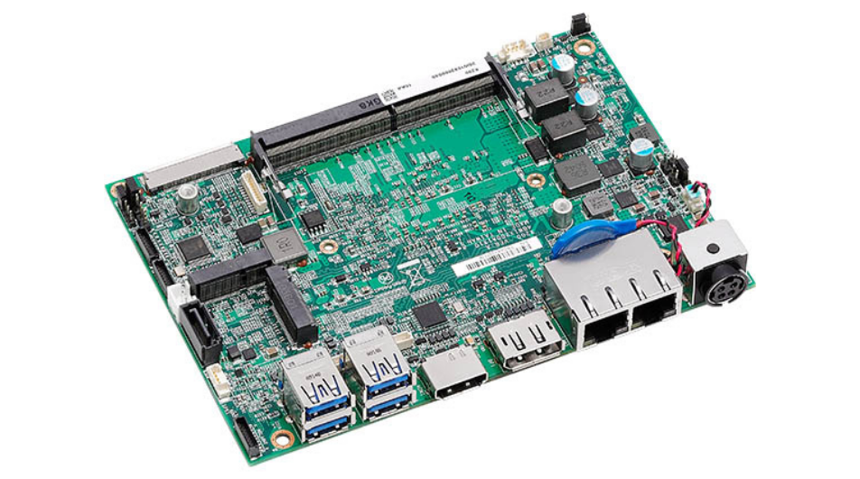
Taiwan-based embedded electronic device manufacturer, NEXCOM has unveiled a 3.5-inch embedded computer board, X200, built around the 11th Generation Intel Core Processor. Decently sized high-performance computer is designed to bring in digital transformation in AI image processing specifically in the health care industry. Powerful graphic processing capabilities render 4K for multiple displays with ease of use. Additionally, advanced wireless communication flexibility has brought in the scope for its deployment in a variety of applications.
The X200 embedded mini-computer board has three versions based on Intel’s processor core varying from 11th Generation Intel i3 processor core to i7 quad-core processor. However, note that the i7 processor variant will only be available on individual requests. Moreover, the Intel UHD graphics on the i3 processor and Iris Xe graphics on the i5 processor makes it an intelligent solution for AI image processing. The hardware comes with rich I/O interfaces for several external and internal connections.
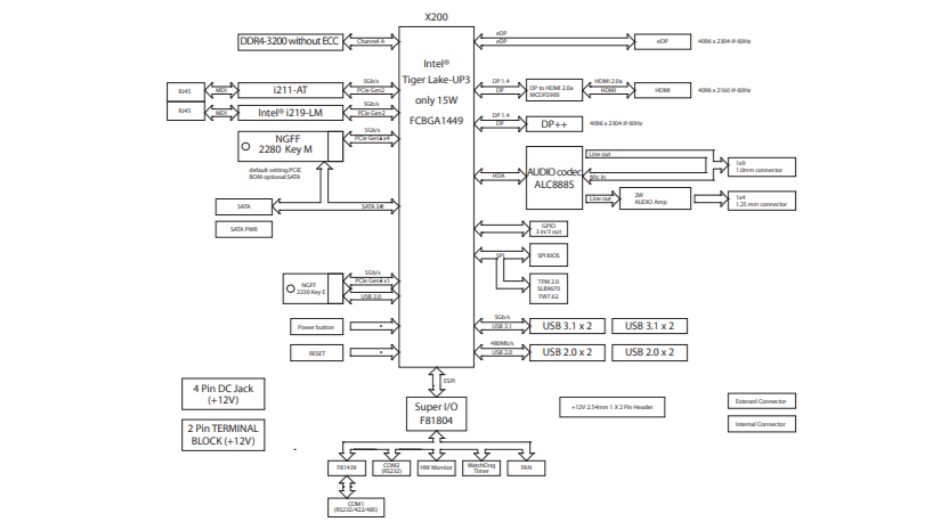
Specifications of X200 Embedded Computer Board
- System:
- 11th Generation Intel dual-core i3-1115G4E processor @2.2 GHz base clock frequency
- 11th Generation Intel dual-core i5-1145G7E processor @1.5 GHz base clock frequency
- 11th Generation Intel quad-core i7-1185G7E processor @1.8 GHz base clock frequency,
- Memory: 1x 260-pin DDR4 SO-DIMM, supports non-ECC, and un-buffered memory up to 32 GB
- Storage:
- 1x M.2 2280 Key M, support PCIe x4 (512GB Maximum)
- 1x SATA 3 & SATA power connector for optional 2.5-inch SSD
- Wireless communication:
- 1 x Intel I219-LM GbE PHY, support Intel vPro platform technology (for Intel® Core™ i5 or above processor)
- 1 x Intel I211-AT GbE LAN
- Graphics:
- Intel UHD graphics on i3 processor
- Intel Iris Xe graphics on i5 processor
- 1x DP++, support 4096 x 2304 @60Hz
- 1x HDMI 2.0, support 4096 x 2160 @60Hz
- 1x eDP, support 4096 x 2160 @60Hz
- Interfaces:
- 4x USB 2.0, internal connector
- 1x Mic-in, 1x Line-out, internal connector
- 1x Speaker-out with 2W/4Ω amplifier, internal connector
- 6x GPIO pin header for 3 x GPI and 3 x GPO
- 1x 4-pin connector for PWM smart FAN
- 1x 12V, 2A power output coming from the main power source for additional module use
- 1x eDP: support 4096 x 2160 @ 60Hz
- Onboard TPM 2.0 (for SKU X200-i5)
- 1x RS232/422/485, internal pin header (COM1)
- 1x RS232, internal pin header (COM2)
- Expansion: 1x M.2 2230 Key E, support optional Wi-Fi modules
- Power:
- 12V DC input via DC Jack
- 2-Pin internal DC input connector as the option
- Software support: Windows 10 and Linux
- Operating temperature: -20°C to 70°C
- Dimensions: 146×102 mm
Visual inspection and diagnosis from the use of medical images can be done through the AI processing capabilities of the X200 embedded computer board. The support for 4K at 60Hz frequency gives the hardware a reduction in latency and easy to make decisions through imagery for preliminary checkups. Also, through support for SATA connectors for 2.5-inch SSD offering expandable storage capacity. The hardware also supports up to 32GB of SRAM through SATA 3 and SATA power connectors.
The 4K flawless imaging brings even the smallest details in x-ray films to life, making automatic detection of abnormal x-ray imaging a reality. This form of visual inspection can assist healthcare professionals in increasing overall efficiency, making more accurate/reliable decisions and misdiagnosis prevention, ultimately, saving more valuable lives than ever.
Currently, the manufacturer has not publicly disclosed any information on pricing. However, you are advised to send an inquiry for more details on the availability. Head to the product page for more information on the capabilities and technical specifications.