Pixblasters Announces New Firmware Updates for Its MS1 Video LED Controller

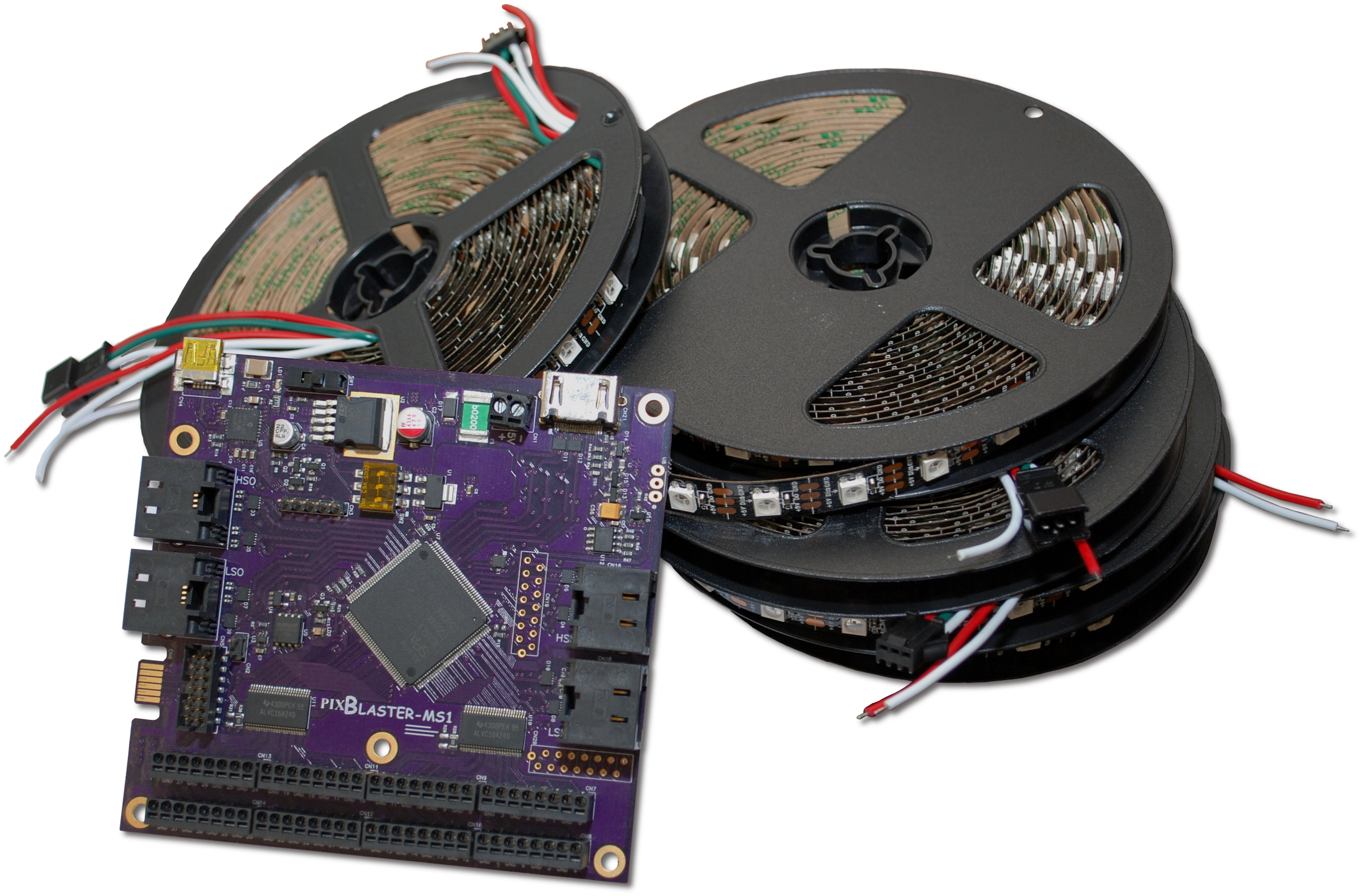
Pixblasters™ has announced the release of new firmware updates for its Pixblasters MS1 Video LED Controller, which enables real-time control of extensive video LED displays built by addressable LED strips.

The firmware updates bring new FPGA LED controllers (ver. 107) that are immediately available to download free-of-charge from https://pixblasters.com/deliverables/

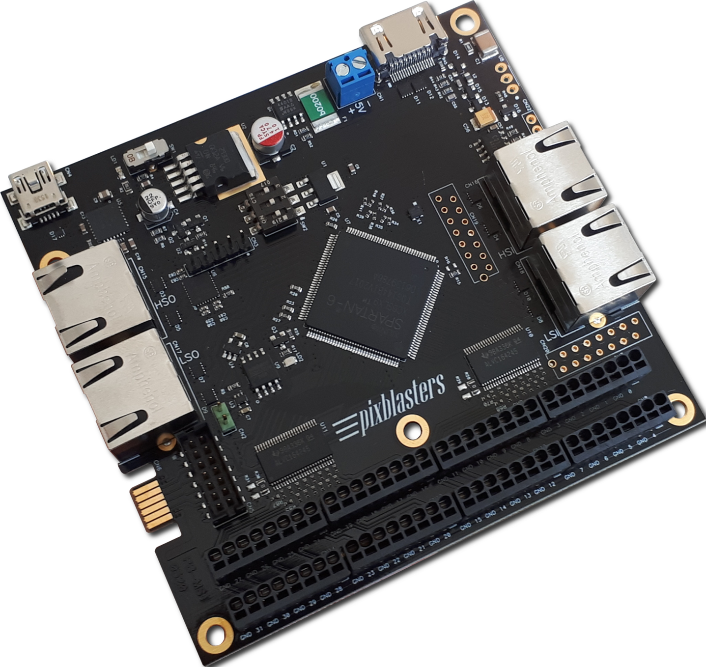
The latest Pixblasters firmware now includes full support for video control of 4-wire RGB LEDs with separated DATA and CLK digital inputs, such as APA102, HD107, SK9822, and others. When used in this control mode, the Pixblasters MS1 Video LED Controller supports 16 outputs, each driving 1,024 RGB LEDs, for a total of 16,384 LEDs controlled by a single controller. Video installations with more than 16,384 LEDs can be synchronously controlled by multiple and chained Pixblasters MS1 controllers.

Pixblasters 3-wire RGB LED support is also improved, and along with the WS2811, WS2812B, WS2815 and similar LEDs, now it also controls GS8208 LEDs.

Mirroring and padding functions are fully implemented. The mirroring function enables compact video LED installations with minimized cabling, e.g. two controllers placed centrally and side-by-side may control a 30 meter (~98 ft) long 30 mm pixel pitch LED ticker with all data cabling not longer than 0.5 meters. The padding function shifts the video image by a couple of pixels and enables outdoor LED strips to be taken out of a weatherproof control cabinet with no loss of first video pixel columns.

A new firmware update is applicable to all Pixblasters MS1 Video LED Controller boards currently deployed in the field. The firmware update procedure is simple and takes no more than a couple of minutes to complete.

Pixblasters has published the PAPP003 application note that describes the FPGA update procedure: https://pixblasters.com/wp-content/uploads/2021/09/papp003-Pixblasters-FPGA-Update-Guide_v1.0.pdf .

The complete procedure is also demonstrated by a short video clip

Demo

Datasheets

Aven Cyclops 3.0 Digital Microscope

Aven Cyclops 3.0 Digital Microscope combines ease-of-use with advanced digital microscope technology in one compact device. The Cyclops 3.0 is an innovative digital microscope that connects directly to an HD monitor as well as a computer, or to both simultaneously with magnification ranges up to 140x. This microscope features built-in HDMI and USB outputs with 4x objective lens and image capture software that includes measurement and editing tools. In addition, the software provides Compare mode, Measurement mode, and Device Control mode. Aven Cyclops 3.0 Digital Microscope increases accuracy and productivity while easing eye strain and user fatigue.

Features

  • Advanced measurement software included for PC Mode (via download)
  • Crystal-clear 1080p full HD
  • USB C – High-speed transmission
  • Built-in 30 LED ring light
  • Included Measurement Software
  • Continuous calibration
  • USB 3.0 output
  • HDMI output

Specifications

  • Package Contents
    • Cyclops 3.0
    • Standard stand
    • USB cable
    • HDMI cable
    • Power supply
    • IR remote control
    • Calibrator
    • 4x objective lens
    • White balance card
    • User’s guide
  • Magnification 13x to 140x magnification
  • 1920*1080 effective pixels
  • 3.8mm to 40mm field of view
  • 22mm to 214mm working distance
  • 1.6A power consumption
  • -5°C to +50°C operating temperature range

more information: https://www.aventools.com/Cyclops-3.0-Digital-Microscope

Digitally Controlled MEMS Oscillator Enables Up to 25% Faster Wireless Charging Mobile and IoT Applications

SiTime Corporation has released the SiT3901 µPower digitally controlled MEMS oscillator (DCXO) for power-sensitive and space-constrained mobile and IoT applications. Ideal for wireless charging systems for smartwatches, activity trackers, hearing aids, wearables, portable medical devices, this new oscillator enables the charger to dynamically tune the resonant frequency, maximizing power transfer and delivering up to 25% faster charging.

The digital control feature on the SiT3901 DCXO eliminates the need for additional passive components on the board, reducing the timing solution area by up to 90%. It offers high resilience to analog noise and stability over the temperature of ±50 and ±100 ppm.

Key Features of SiT3901 MEMS Oscillator

  • Ultra-low 105 micro-amps of current consumption (typical)
  • Ultra-wide digital pull range (up to 15%) for output frequency
  • Stability over the temperature of ±50 and ±100 ppm
  • Wide temperature range, from -40 degree C to +85 degree C
  • Ultra-small 1.5 mm x 0.8 mm package size
  • Programmable frequency from 1 MHz to 26 MHz
  • Ideal for space-saving applications
  • Helps reduce BOM costs

more information: https://www.sitime.com/products/digitally-controlled-oscillators/sit3901

TPS7A20 Ultra-Low-Noise Low Dropout (LDO) Linear Regulator

Texas Instruments’ 300 mA, high PSRR regulator is suitable for battery-powered applications

Texas Instruments’ TPS7A20 is an ultra-small, low-dropout (LDO) linear regulator that can source 300 mA of output current. The device provides low noise, high PSRR, and excellent load and line transient performance that can meet the requirements of RF and other sensitive analog circuits. Using innovative design techniques, the TPS7A20 offers ultra-low-noise performance without adding a noise-bypass capacitor. This regulator provides the advantage of low quiescent current making it ideal for battery-powered applications. With an input voltage range of 1.6 V to 6.0 V and an output range of 0.8 V to 5.5 V, the TPS7A20 can be used for a wide variety of applications.

The device uses a precision reference circuit to provide maximum accuracy of 1.5% overload, line, and temperature variations. The TPS7A20 features an internal soft-start to lower the inrush current minimizing the input voltage drop during start-up. The regulator is stable with small ceramic capacitors, allowing for a small overall solution size. The TPS7A20 has a smart enable input circuit with an internally controlled pulldown resistor that keeps the LDO disabled even when the EN pin is left floating and helps eliminate the external components used to pulldown the EN pin.

Features

  • Low output voltage noise: 7 µVRMS
    • No noise-bypass capacitor required
  • High PSRR: 95 dB at 1 kHz
  • Input voltage range: 1.6 V to 6.0 V
  • Output voltage range: 0.8 V to 5.5 V
  • Output voltage tolerance: ±1.5% (max.)
  • Very low dropout:
    • 140 mV (max.) at 300 mA (VOUT = 3.3 V)
    • 145 mV (max.) at 300 mA (VOUT = 3.3 V, DBV)
  • Very low IQ: 6.5 µA
  • Low inrush current
  • Smart enable pulldown
  • Stable with 1 µF minimum ceramic output capacitors
  • Packages:
    • 1 mm x 1 mm X2SON
    • 0.603 mm x 0.603 mm DSBGA
    • 2.90 mm x 1.60 mm SOT23-5

Application Circuit

more information: https://www.ti.com/product/TPS7A20

Diodes Incorporated AP64200Q Automotive Synchronous Buck Converter

Diodes Incorporated AP64200Q Automotive Synchronous Buck Converter fully integrates a 150mΩ high-side power MOSFET and an 80mΩ low-side power MOSFET to provide high-efficiency step-down DC-DC conversion. The AP64200Q design is optimized for Electromagnetic Interference (EMI) reduction.

The Diodes Incorporated AP64200Q Converter is easily used by minimizing the external component count due to its peak current mode control adoption. The device has a proprietary gate driver scheme to resist switching node ringing without sacrificing MOSFET turn-on and turn-off times, which reduces high-frequency radiated EMI noise caused by MOSFET switching. Additionally, the AP64200Q also features Frequency Spread Spectrum (FSS) with a switching frequency jitter of ±6%, which reduces EMI by not allowing emitted energy to stay in any one frequency for a significant period of time.

The AP64200Q is available in a SO-8EP package with a 3.8V to 40V input voltage range.

Features

  • AEC-Q100 qualified for automotive applications
    • Device temperature grade 1 -40°C to +125°C TA range
  • 3.8V to 40V VIN
  • 0.8V to VIN Output Voltage (VOUT)
  • 2A Continuous output current
  • 0.8V ±1% Reference voltage
  • 25µA Low quiescent current (pulse frequency modulation)
  • Adjustable switching frequency of 100kHz to 2.2MHz
  • External clock synchronization of 100kHz to 2.2MHz
  • Up to 88% efficiency at 5mA light load
  • Proprietary gate driver design for Best EMI reduction
  • Frequency Spread Spectrum (FSS) to reduce EMI
  • Low-Dropout (LDO) mode
  • Precision enable threshold to adjust UVLO
  • Protection circuitry
  • Undervoltage Lockout (UVLO)
  • Output Overvoltage Protection (OVP)
  • Cycle-by-cycle peak current limit
  • Thermal shutdown
  • Totally lead-free and fully RoHS compliant
  • Halogen and antimony free

Application Diagram

Block Diagram

more information: https://www.diodes.com/part/view/AP64200

Microchip Technology AT24CSWx Serial EEPROMs

Microchip Technology AT24CSWx Serial EEPROMs are designed to be I2C compatible (two-wire) with a security register and software write protection. These EEPROMs feature bidirectional data transfer protocol and filtered inputs for noise suppression. The AT24CSWx EEPROMs operate at a 1.7V to 3.6V voltage range, 1mA ultra-low active current, 0.8µA standby current, and -40°C to 85°C temperature range. The AT24CSW01X / AT24CSW02X EEPROMs provide 8-Byte page write mode and AT24CSW04X / AT24CSW08X EEPROMs offer 16-Byte page write mode with partial page writing. These EEPROMs are available in 5-lead SOT23 and 4-ball ultra-thin WLCSP packages.

Features

  • Random and sequential read modes
  • Within 5ms self-timed write cycle
  • >4000V ESD protection
  • Software write protection of the EEPROM array:
    • Five configuration options
    • Protection settings can be made permanent
  • Bidirectional data transfer protocol
  • Schmitt triggers and filtered inputs for noise suppression
  • I2C-compatible (two-wire) serial interface:
    • 100kHz standard mode, 1.7V to 3.6V
    • 400kHz fast mode, 1.7V to 3.6V
    • 1MHz fast mode plus (FM+), 1.7V to 3.6V
  • AT24CSW01X / AT24CSW02X:
    • 8-Byte page write mode
  • AT24CSW04X / AT24CSW08X:
    • 16-Byte page write mode

Block Diagram

more information: www.microchip.com

EPC2216 – 15 V GaN Power Transistor

The EPC2216 from Efficient Power Conversion is a GaN Transistor with Gate Threshold Voltage 0.7 to 2.5 V, Drain Source Voltage 15 V, Drain Source Resistance 20 to 26 milli-ohm, Continous Drain Current 3.4 A, Pulsed Drain Current 28 A.

Specifications

  • Configuration: Single
  • Gate Threshold Voltage: 0.7 to 2.5 V
  • Drain Source Voltage: 15 V
  • Drain Source Resistance: 20 to 26 milli-ohm
  • Continuous Drain Current: 3.4 A
  • Pulsed Drain Current: 28 A
  • Total Charge: 0.87 to 1.1 nC
  • Input Capacitance: 98 to 118 pF
  • Output Capacitance: 66 to 99 pF
  • Temperature operating range: -40 to +150 °C
  • Qualification: AEC-Q101
  • RoHS Compliant: Yes
  • Package-Type: Die
  • Package: BGA
  • Applications: High-Speed DC-DC conversion, Lidar/Pulsed Power Applications, Lidar for Augmented Reality Applications
  • Dimensions: 0.85 x 1.2 mm

more information: https://epc-co.com/epc/Products/eGaNFETsandICs/EPC2216.aspx

TPS7A78 – 120-mA smart cap-drop low-dropout (LDO) linear voltage regulator


Texas Instruments TPS7A78 Low-Dropout (LDO) Linear Regulator improves the overall efficiency and standby-power in power-supplies in an easy-to-use, non-magnetic approach to AC/DC conversion. The TPS7A78 uses a capacitor-drop architecture to lower the AC source voltage before actively clamping the rectified voltage. The device then regulates this rectified voltage down to the application-specific operating voltage. The unique architecture of the device allows the standby power to be reduced to just a few 10s of milliwatts. The TPS7A78 switched-capacitor stage reduces power losses by stepping down the rectified input voltage by a factor of four and increasing the output-to-input current by the same ratio, as given by PIN ≅ POUT and VIN ≅ VOUT × 4. Compared to a traditional capacitor-drop (cap-drop) stage, this step down reduces input current, thus minimizing the value of the capacitance needed.

Electricity-metering applications, where the power supply must be reliable and magnetic tamper-proof, benefits from using the TPS7A78 because this device does not require external magnetics. This feature makes complying with IEC 61000-4-8 easier while minimizing magnetic shielding cost. The TPS7A78 also comes with a user-programmable, power-fail detection threshold that can provide an early alert to power failures and enable shutdown before complete power loss. The power-good indicator (PG) is also provided for sequencing or resetting a microcontroller.

Features

  • Non-isolated power solution for ≥ 18VAC RMS
    • Up to 75% efficiency
    • 15mW (typical) standby power consumption
    • Line-voltage, cap-drop capacitor as small as 1/4th the size of linear solutions
  • Available in fixed output voltages
    • 1.3V to 5V (50mV steps)
  • Power-fail detection
  • Power-good indication
  • 1% typical accuracy
  • Package
    • 5mm x 6.5mm HTSSOP-14 (PWP)

Block Diagram

more information: https://www.ti.com/product/TPS7A78

Various Applications of Photonics and Optics

Photonics and optics are fields of engineering and physics that deal with highly complex equipment, components, and tools. The advancements in Photonics and optics are helping to form better industrial standards and help with further technological development around the world. In this article, we will discuss the applications of photonics and optics across different industries.

You may have LED lights, TVs, digital cameras, high-definition cameras, water-proof electrical gadgets, miniaturized PCBs, and more. These are all the developments made possible due to photonics and optics. Let’s dive a little deeper and explore how lasers and laser components have been vital in technological development.

Security and Defense Industry

Engineering plays a major role in developing the latest and modern equipment in the defense and security industry. From radiological, nuclear, and chemical to biological weapons, threat detection requires complete systems comprising modern photonics and optics. These electronic and highly advanced systems are key to improve defense and security.

For instance, when talking about photonics and optic electronics, optics-based sensors and components are used in surveillance technology of the finest standards. Laser technology is critical for the military since they rely on the most advanced and high-tech gadgets and assets.

Telecommunications Industry

The telecommunications industry is no different. Surely, you may know about relay towers and carrier towers. It is safe to say that the development of 5G would’ve taken a lot more years without photonics and optics developments. The optical fiber and laser components that ensure speed and lightning-fast internet connection are some of the most notable developments in the laser industry.

Energy Sustenance and Conservation Industry

We cannot live an efficient life without energy sources. It is highly important to assess and value the critical nature of optics and laser components that play a vital part in manufacturing better and more efficient energy-generating systems. When optics overlaps with photonics, a combination of materials, their chemistry, and thermal science pave the way to the generation of the latest solar modules and cells. LED-based lighting is an efficient energy conservation approach that has been possible only through the advancement of optics and photonics experts in their respective fields.

Quantum Physics and Engineering Industry

Quantum physics and engineering has laid the foundation of the next and advanced computer generation. Some of the notable achievements include navigation across environments that are GPS-blind. Moreover, other accomplishments of quantum engineering and physics have led to the development of ultra-precise and potentially the most accurate sensors and atomic clocks globally. This is all possible through the use of lasers and laser components that boast the right manufacturing techniques, high-quality material, and devices and electronics to deliver the right results.

Conclusion

Without laser technology and upgrades, most industries would still be tackling the common issues and continue using traditional technology. The expansion and innovation of photonics and optics are vital for energy conservation, medicine development, advancement in computing technology, and modern optics systems.

POV (Persistence of Vision) – Open-Source Arduino Nano Hardware

This is an easy and simple hardware to create a POV display. The hardware consists of a Hall sensor, Arduino Nano, 17 x 5mm LEDS of various colors, etc. The Hall Sensor is connected to analog pin A5 with a pull-up resistor. The circuit works with 3.7V to 5V DC and a 3.7V battery is ideal to use. The user may use as many LEDS as required. This project can also be used to create many applications such as Bar-Graph display, LED light effects. A large 8.5 mm hole is provided to mount the motor coupling. Refer to the diagram for mounting the hall sensor, motor, and magnet.

POV or persistence of vision refers to the optical illusion that occurs when visual perception of an object does not cease for some time after the rays of light proceeding from it have ceased to enter the eye. The illusion has also been described as “retinal persistence”, “persistence of impressions”, simply “persistence” and other variations.

More Information is available here: http://electronoobs.com/eng_arduino_tut21.php

Arduino Nano Pins

  • Hall Sensor: Analog Pin A5 with Pull Up resistor, Normally High and goes low when magnet is near to the sensor.
  • LED D2 to D18: Arduino Pin A4, A3, A2, A1, A0, D13, D2, D3, D4, D5, D6, D7, D8, D9, D10, D11, D12
  • LED D1 : This LED is optional and not installed, user may assemble this LED if the board is used for other application.

Arduino code is available to test the board. The code makes use of 6 LEDs, refer to the diagram to mount the PCB on the motor shaft, Magnet, and Hall sensor potion.

Credits: Original Author of the Arduino Code is Palak Mehta.

Features

  • Supply 3.7V to 5V DC
  • On Board 17X LEDs – Various Colours
  • On Board Hall Sensor
  • Multiple Mounting Holes for Mounting the battery
  • 5MM Mounting Hole for Motor Shaft
  • PCB Dimensions 194.95  x 29.37 mm

Schematic

Connections

Mounting on motor

Parts List

NOQNTYREFDESCMANUFACTURERSUPPLIERSUPPLIER PART NO
11CN14 PIN MALE HEADER PITCH 2.54MMWURTHDIGIKEY732-5317-ND
23D1,C1,R21DNP
31C247uF/25VNICHICONDIGIKEY493-15345-3-ND
41C31uF/10V SMD SIZE 0805 MURATA/YAGEODIGIKEY
52D2,D3LED-ORANGE 5MM THTWURTHDIGIKEY732-5018-ND
62D4,D5LED-YELLOW 5MM THTBROADCOMDIGIKEY516-3193-2-ND
74D6,D7,D8,D9LED-RED 5MM THTSUN LEDDIGIKEY1497-1031-ND
88D10 to D17LED-GREEN 5MM THTCREEDIGIKEYC503B-GCN-CY0C0791-ND
91D18LED-BLUE 5MM THTTTDIGIKEY365-1180-ND
102R1,R200E SMD SIZE 0805MURATA/YAGEODIGIKEY
1116R2 TO R17330E 5% SMD SIZE 0805MURATA/YAGEODIGIKEY
121R18100E 5% SMD SIZE 0805MURATA/YAGEODIGIKEY
131R1910E 5% SMD SIZE 0805MURATA/YAGEODIGIKEY
141R2210K 5% SMD SIZE 0805MURATA/YAGEODIGIKEY
151U1ARDUINO NANOARDUINODIGIKEY1050-1001-ND
161U2A1102LUA-T OR A3144ALLEGRODIGIKEY620-1003-ND

Gerber View

Photos

Video

A1102 Datasheet

TOP PCB Companies