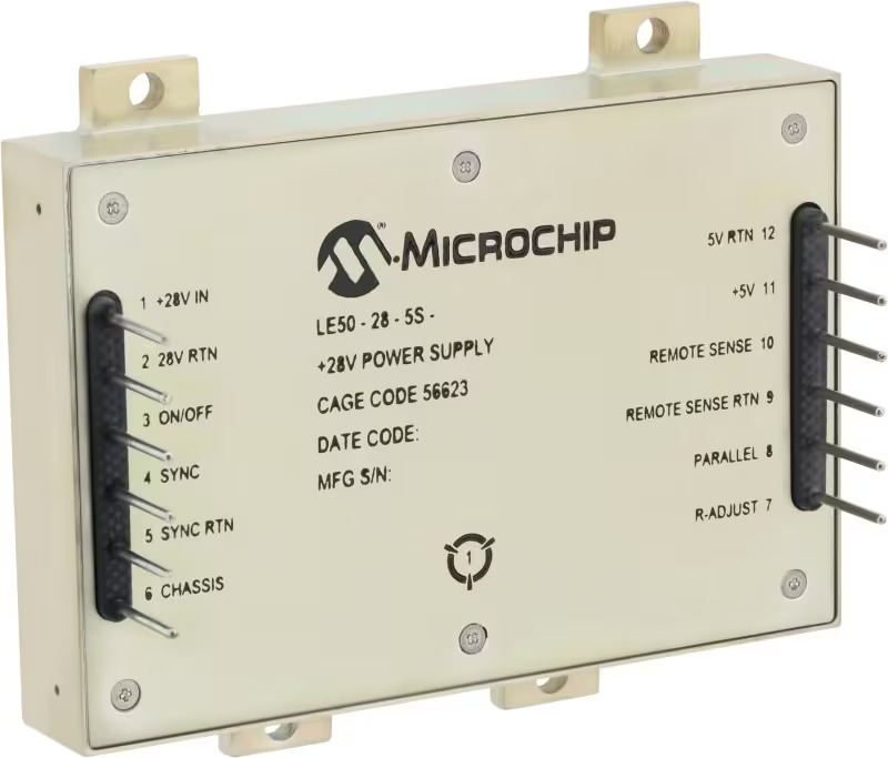
Microchip has recently introduced a series of radiation-tolerant DC-DC converters LE50-28 series, that are specifically designed to work for Lower Earth Orbit (LEO) satellites. The power supplies come in nine variants with single and triple output options.
The company mentions that the growing Low Earth Orbit (LEO) market demands reliable, cost-effective, and configurable space-grade solutions for 5G communication, cube satellites, and IoT applications. So the LE50-28 series of isolated DC-DC converters meet this need with off-the-shelf, 50W, radiation-tolerant power converters available in nine variants, offering single and triple outputs from 3.3V to 28V. The LE50 series bridges the gap between non-radiation-tolerant commercial converters and expensive radiation-hardened ones, providing an affordable, mission-compatible option.
The LE50-28 series offers radiation tolerance and high performance in a compact size, making it easy for designers to integrate into their devices. It provides a cost-effective alternative to expensive bespoke converters for satellite applications with strict SWaP constraints. The series features up to 50 Krad total ionizing dose and 37 MeV×cm²/mg latch-up immunity for LEO applications. The converter weighs 120 g, and the EMI filter weighs 82 g, meeting MIL-STD-461 for quick qualification. This makes the LE50-28 a balanced choice for performance, size, weight, and radiation tolerance.
The LE50-28 series offers 80% power conversion efficiency at full load, reducing payload size and weight by minimizing energy storage needs. Available in single- and triple-output versions, it supports up to 50W per unit and up to 200W by paralleling four units. The triple-output version provides three unique outputs in the same footprint. Operating from a 28V bus, the converters output between 3.3V and 28V. The EMI filter reduces interference, and the converters boast a mean time between failures of one million hours.
The triple-output LE50-28 is designed to provide multiple outputs
Microchip DC-DC Converter Specifications
28V Input Voltage
Up to 50W Output Power in a low-profile design
High MTBF (Mean Time Between Failures) and exceptional efficiency
Scalable Output Power: Parallel up to four units for a 200W solution
EMI Compliant with additional filter and radiation-tolerant designs
Output Configurations: Single and triple outputs tailored for New Space and LEO applications
Robust Switching Regulators: Peak current mode-controlled single-ended forward converter topology with inherent single-event immunity
Enhanced Functionality on Single-Output Versions: Includes remote sense, output voltage adjust, and parallel connection capabilities
Microchip has not yet released pricing information for its radiation-tolerant DC-DC converter family. However, comprehensive datasheets for all nine modules are available on their website, offering detailed specifications and technical information. Further insights into the converter’s capabilities and potential applications can be found in the press release on Microchip’s website.
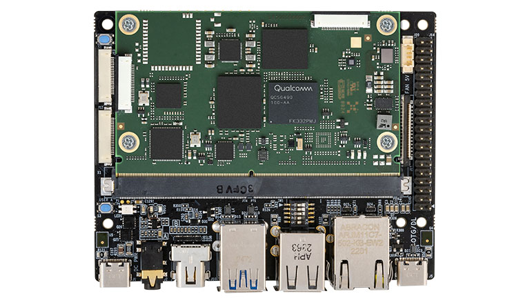
Avnet recently released a development kit for its Small Mobility ARChitecture (SMARC) 2.1.1 compute module which uses Qualcomm’s QCS6490 processor–the QCS6490 Vision-AI Development Kit. Equipped with high-performance cores within the SMARC module and provision pins for multiple cameras, the development kit opens doors for Edge-AI applications, Multi-camera Security Systems with Recognition, service and industry robots and many more IoT applications.
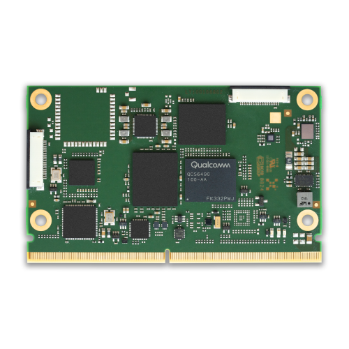
The embedded QCS6490 processor-based SMARC compute module, the MSC SM2S-QCS64, integrates the Qualcomm Kryo 670 CPU which contains up to eight cores: four Arm Cortex®-A78 cores, four Arm Cortex-A55 cores, Qualcomm Adreno 643 GPU, Qualcomm Adreno 633 VPU (enables high-resolution video encoding and decoding up to 4K60) and the Qualcomm Hexagon processor. There’s also the 6th gen Qualcomm AI Engine with 13 TOPS that provides robust AI processing capabilities, ideal for machine learning and inferencing tasks. Meanwhile, the Spectra 570L ISP within the SMARC module supports up to five concurrent camera inputs, making it suitable for complex imaging systems such as autonomous vehicles or surveillance.
Other Features of SM2S-QCS6490 SMARC Compute Module:
8GB LPDDR5 SDRAM, 64GB UFS Flash Memory
2x USB 3.1 (2L), 3x USB 2.0 interfaces
2x PCIe Gen3 (1L), 1x PCIe Gen3 (2L) interface
1x DisplayPort 1.4 (2L) interface
1x MIPI-DSI (4L), 1x eDP (4L) display interfaces
2x MIPI-CSI (4L) camera 22-pin connectors
2x MIPI-CSI (4L, 2L) via SMARC edge connector
2x 1 Gigabit Ethernet interfaces
Wi-Fi 6 / BT 5 (SMARC module assembly option)
TPM module (SMARC module assembly option)
UART, SPI, I2C, I2S, GPIO interfaces
HW Key manager, ECC, Secure boot, Crypto
While the SMARC Compute Module does allow the connection of up to 4 cameras, the IO components of the QCS6490 Vision-AI Development Kit only add to connectivity capabilities. The Vision AI I/O board of the development kit is connected to the SMARC 2.1.1 module via an edge connector. The carrier board also has M.2 key-M slot for NVME storage and a M.2 key-E slot enabling wireless connections.
In addition to a display port 1.4 (2L) interface, the QCS6490 Vision-AI Development Kit has an audio subsystem which includes two PDM microphones, stereo audio Codec, digital audio interface and analog audio jack I/O.
Other features of the Vision AI I/O Board:
I/O Interface:
40-Pin Pi-HAT header
4-pin CAN header
10-pin Test IO header
Gigabit Ethernet RJ45 connector
miniDP and 1x MIPI-DSI display connectors
2x button switches and RGB User LED
Other Features:
2-pin RTC battery header
2x button switches & RGB User LED
Power:
9V/3A (USB-C PD)
Operating Temperature:
-40°C to 85°C
Avnet includes a Yocto-based Linux BSP with the development kit and some other aids. There are also some accessories available with the kit like MIPI CSI IMX477 12MP camera, NVME SSD storage (M.2 Key M 2280 memory module) and MIPI DSI 7-inch touchscreen LCD display. More information on the QCS6490 Vision-AI Development Kit is available on Avnet’s website along with a product brief.
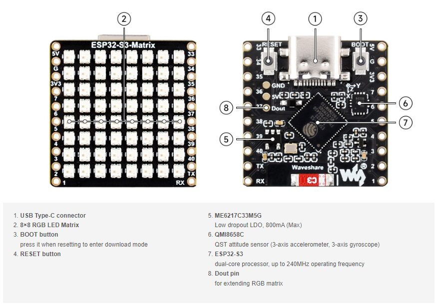
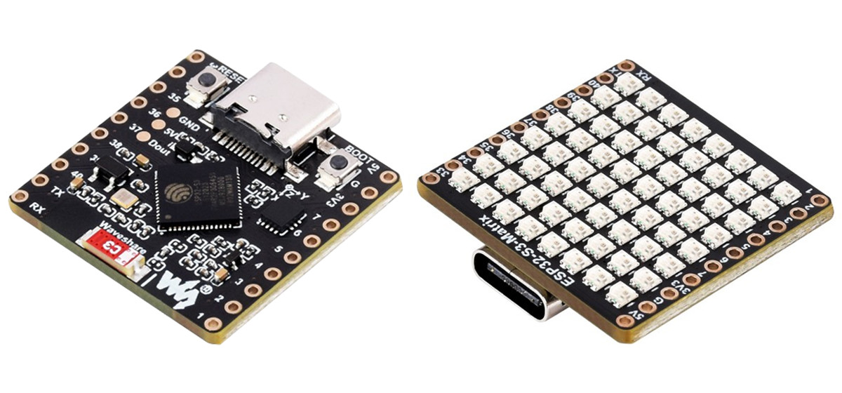
Waveshare ESP32-S3-Matrix Dev Board is an ESP32-S3-based development board that features an 8×8 addressable RGB LED Matrix(64 LEDs in total), 15 usable GPIO pins, and a 9-axis attitude sensor that can be used for robotics and motion control applications. In addition to that it is capable of doing UART, SPI, PWM, and more.
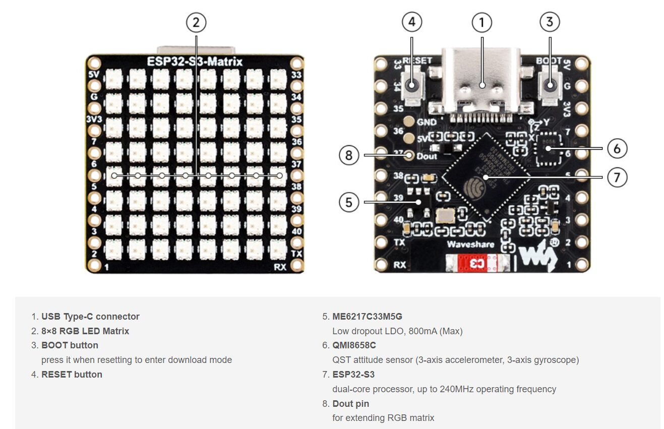
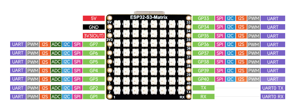
Like other products from this company, this board comes with a detailed diagram showing all its parts. This makes it easy to find and fix any problems. They also provide another diagram showing the connections, so you can easily start using it or add other devices.
Waveshare ESP32-S3-Matrix Dev Board Specifications:
MCU: Espressif Systems ESP32-S3FH4R2
CPU: Dual-core Tensilica LX7 @ up to 240 MHz with vector instructions for AI acceleration
Memory:
512KB RAM
2MB PSRAM
Storage: 4MB QSPI flash
Connectivity:
2.4 GHz WiFi 4
Bluetooth 5.0 LE with support for long-range, up to 2Mbps data rate, mesh network
LED Matrix: 8 x 8 Addressable RGB LEDs
Sensor: QMI8658C 6D MEMS IMU with 9-axis sensor
3-axis accelerometer
3-axis gyroscope
3-axis magnetometer
Connectivity and Interfaces:
Up to 15x multi-function GPIO pins via 2x 10-pin headers with 2.54mm pitch
Peripheral interfaces include SPI, I2C, UART, ADC, PWM
Antenna: 3D PCB Antenna
Power Management: ME6217C33M5G low dropout LDO capable of delivering 800mA (Max)
For software, you can program the board using ESP-IDF, Arduino IDE, or MicroPython, which are available online. More information like the pinout diagram, installation guide, examples, and other resources can be found on their wiki page.
Previously we have written about many laser engravers like the AlgoLaser Delta, ATEZR P20 PLUS, and many similar but all of those laser cutters and engraver has one thing in common, they were designed for a beginner or a hobbyist who just wanted to get started with engraving, and is not recommended for everyday use. But the xTool P2 is different, not only it’s robust and powerful but it includes various software features that even kids can operate this tool with easily making it suitable for not only commercial but also educational use.
The xTool P2 is packed, and I mean it, when you look at a standard beginner-grade laser engraver, it will be shipped to you with an air assist, exhaust, and water chiller that you need to attach to run the CO2 laser properly, but the xTool P2 is all in one so it called a “desktop” machine. This beast weighs 99 pounds or 45Kgs and takes up 39.4 x 25.1 x 10.6 inches of counter space, so it will take up to two men to move that around.
Let’s look at some of the major features of this tool, the xTool P2 is a 55-watt CO2 Laser Cutter built for creating customized home decor and furniture or you can start a small business of yours as it has a calculated lifespan of 6000~8000h. It can cut 20mm transparentacrylic in one pass and features two built-in 16MP cameras to position drawings and patterns precisely. The first camera gives a wide view of the entire work area for easy positioning. The second camera provides a detailed view for precise engraving in specific areas. On top of that it can engrave on curved surfaces with automatic surface scanning and focal length adjustment. The enlarged bed size and new pass-through feature with a conveyor feeder allow for larger and longer projects. The tool can also be equipped with a Riser base that increases the inner height to 215mm, ideal for customizing items like suitcases. Finally, there is also an additional rotary engraving accessory available that works on tumblers, mugs, spheres, and rings. Unlike traditional CO2 laser cutters, this comes with a built-in air exhaust system, with a filter making it safe and easy to use indoors.
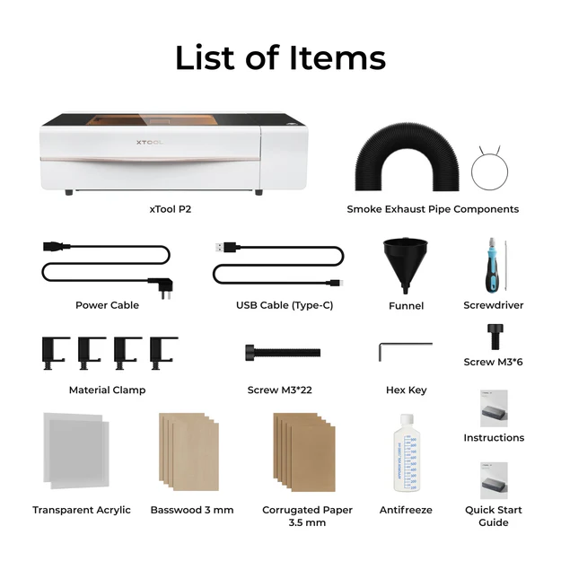
What’s included in the Box?
The P2 CO2 laserbasic kit comes with a fully assembled laser cutter, a screwdriver, slats, small material clamps, an air duct hose, antifreeze, a funnel, and samples of wood and acrylic for engraving. Free software is available on xTools websites for creating artwork and operating the machine.
Additionally, there are other accessories available that have to be bout separately like the riser kit, air purifier, fire safety kit, conveyor feeder, rotary engraving accessory, and more materials for engraving.
How to Assemble the xTool P2
Your xTool P2 should arrive fully assembled in a large box, with packing materials, so you need to have some tools to cut the packaging material and get your machine out. you also need someone to help you with moving the machine from one place to another as it’s heavy. once you set up the machine on your table you need to remove some padding, and protective stickers, and access the laser tube with a few screws. there you need to fill the tube with a mixture of water and Antifreeze. The Antifreeze will be provided by the company. it would help if you made a dilute solution of antifreeze with purified water before filling the machine. The machine also comes with a detailed setup manual but for more information, you can check out the video on their website or there are articles and videos to help you learn more about the engraver.
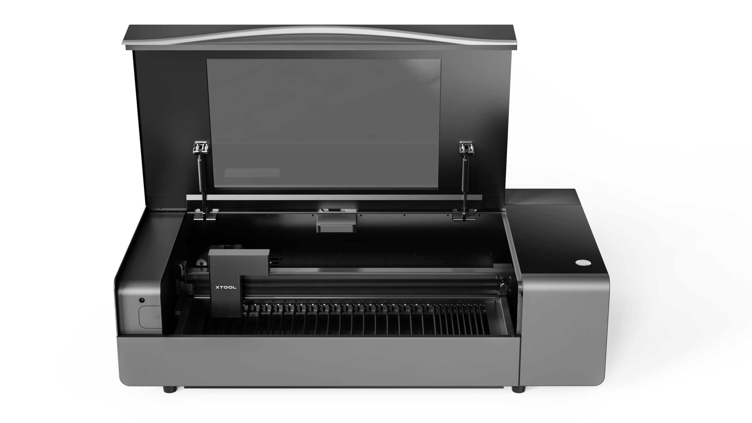
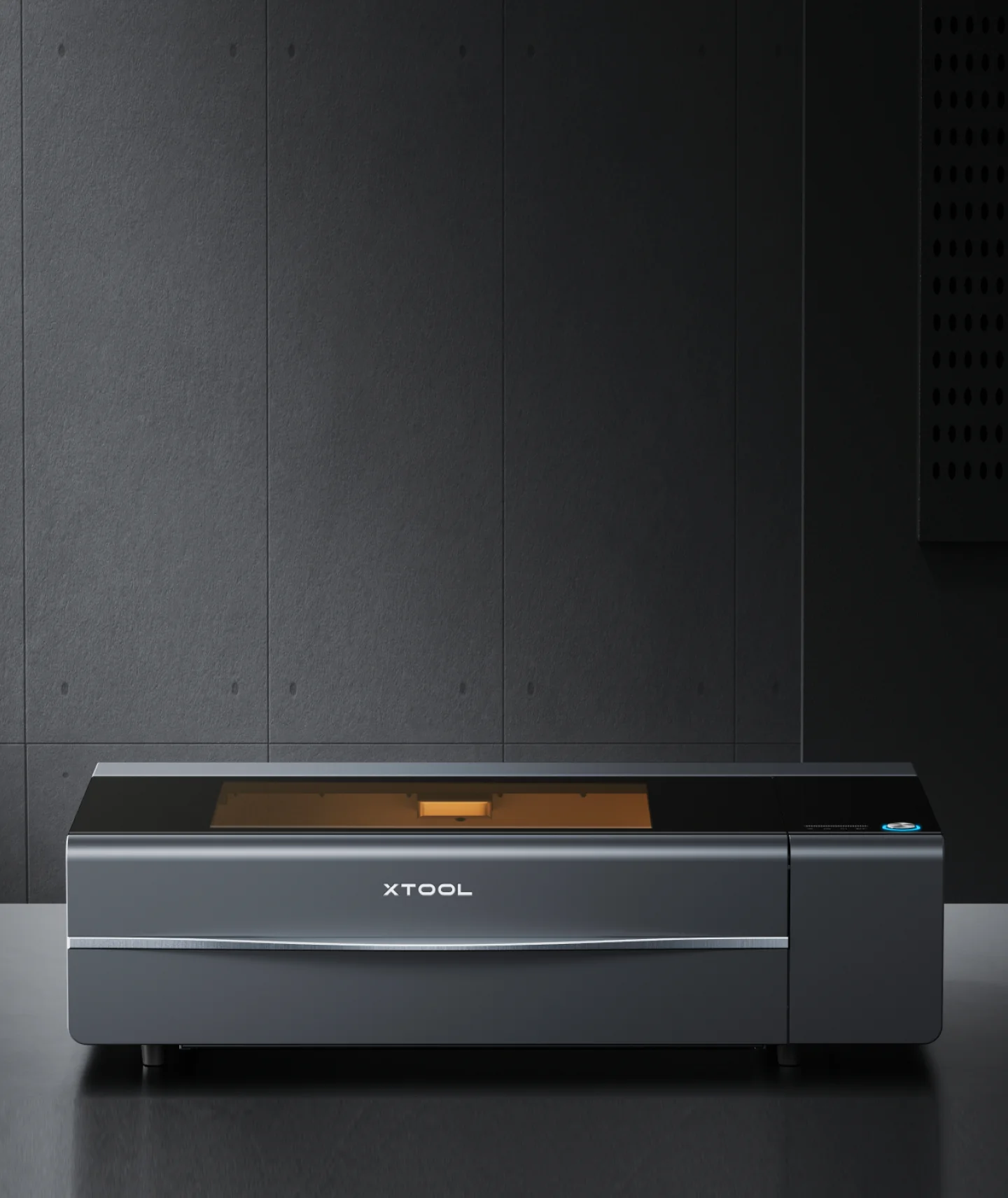
xTool P2 Design and Look
The engraver is fully enclosed and resembles a metal cabinet with a tinted glass top. on the right-hand side, you will find a switch and display, the display gives you access to progress bar temperature readings and a few other information. The lid features hydraulic hinges, making it effortless to open. Inside, the black-on-black interior is neatly organized, with the laser’s wiring securely housed within a robust cable chain.
The Xtool P2 laser only operates when the lid is locked, ensuring safety. The enclosed has air vents at the bottom, which are discreet but you should be careful because it’s big enough that your hand can get under the gap. It features two 16MP cameras for wide-angle and detailed positioning these cameras are responsible for the machine’s 0.3mm accuracy. The focus of this machine is very precise 0.01mm to be exact, this tiny beam delivers precise lines, and the 55W CO2 laser cuts and engraves faster than any other generic engravers out in the market. it also has a Built-in air assist to prevent charring and a powerful fan removes smoke via a hose or optional air purifier. The air purifier is effective but expensive; using an exterior vent may be more cost-effective.
The P2 requires a computer connection, ideally a laptop for the initial USB setup, after which it can connect via WiFi or Ethernet. A start button ensures the machine is not left unattended. It automatically focuses using the material height provided in the software or its cameras. The spacious interior is effective without optional accessories, though its large size can be cumbersome, occupying a 42-inch counter. For pass-through use, a sturdy, open table is needed, preferably in a garage. Access to all sides is necessary for plugs, hoses, and compartments. Key components include the power cord and switch at the back right, emergency button on the right, air duct and ports on the left, and optional fire safety kit connection behind. The CO2 tube at the back requires access only for cooling fluid checks.
xTool P2 Laser Cutter and Engraver Specifications
Laser Power: 55 watts
Laser Type: CO₂
Work Area: 26 x 14 inches
Precision: 0.01mm
Max Speed: 600mm/s
Max Material Thickness: 20mm
Machine Footprint: 1000 x 639 x 268mm (39.4 x 25.1 x 10.6 inches)
Cutting Platform: Metal slats and baseplate included
Connectivity: USB, Wi-Fi, Ethernet
Interface: One Button
Enclosed: Yes
xTool P2 Engraving / Cutting Capabilities
The toll can effortlessly cut through wood up to 18mm and acrylic up to 12mm. Its software includes preset starting points for various materials, ensuring accurate results. The machine’s dual cameras enable precise alignment for projects, allowing for easy corrections and adjustments.
Testing various materials, including wood, acrylic, and metal, yielded impressive results with clean cuts and precise engravings.
The P2’s versatility extends to engraving small items like pencils and slicing through coated metal. Overall, it delivers exceptional performance across a range of applications, making it a valuable tool for creators.
Software for xTool P2
xTool offers free software called xTool Creative Space for designing projects and operating the laser. It is available for Windows, Mac, macOS, and iOS. The software is user-friendly, equipped with features for beginners, and optimized for your laser.
It allows you to draw shapes, and vector lines, and add text, and it supports importing JPG images. Material presets make it easy to get started with common projects. For advanced users, the P2 is also compatible with LightBurn. More details about the software can be found here.
Educational Applications of the xTool P2
The xTool P2 is not just for businesses or hobbyists; it is also an excellent tool for educational settings. Its capabilities can be seamlessly integrated into classroom activities, enhancing STEM education and creative projects. The xTool P2 can help teachers introduce students to cutting-edge technology, which can dramatically improve their DIY! skills and add to their hands-on learning experience. Skools and universities can set up maker fairs exhibitions or creative challenges where the students can learn from simple engravings to complex models. Students can explore the principles of physics, engineering, and design by working on projects that involve cutting and engraving different materials.
To support educational initiatives, xTool offers an Educational Bundle and free courses. These resources provide educators with the tools and knowledge needed to effectively incorporate the xTool P2 into their teaching. For more information on the xTool P2 Educational Bundle and free courses, visit the Makeblock website:
The xTool P2 is a Class 4 laser that requires safety precautions during use. It has a locked lid and shielded window, but a small ventilation gap exists at the bottom. Keep children and pets away while operating. Never leave the machine unattended and have a fire extinguisher nearby. Avoid using materials that can melt, ignite, or produce toxic fumes.
The xTool P2 is a powerful CO2 laser ideal for small businesses. It’s easy to use, with features like automatic alignment and presets for various materials. It can cut through wood up to 18mm thick and engrave on various materials. The pass-through and riser options allow for larger projects. While it requires ample space and careful setup, its versatility and features make it a valuable investment. The xTool P2 Educational Bundle will cost you around S $5,439.00 and can be found in the Makeblock web store.
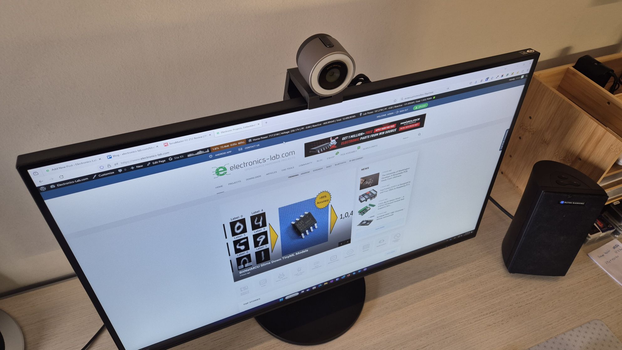
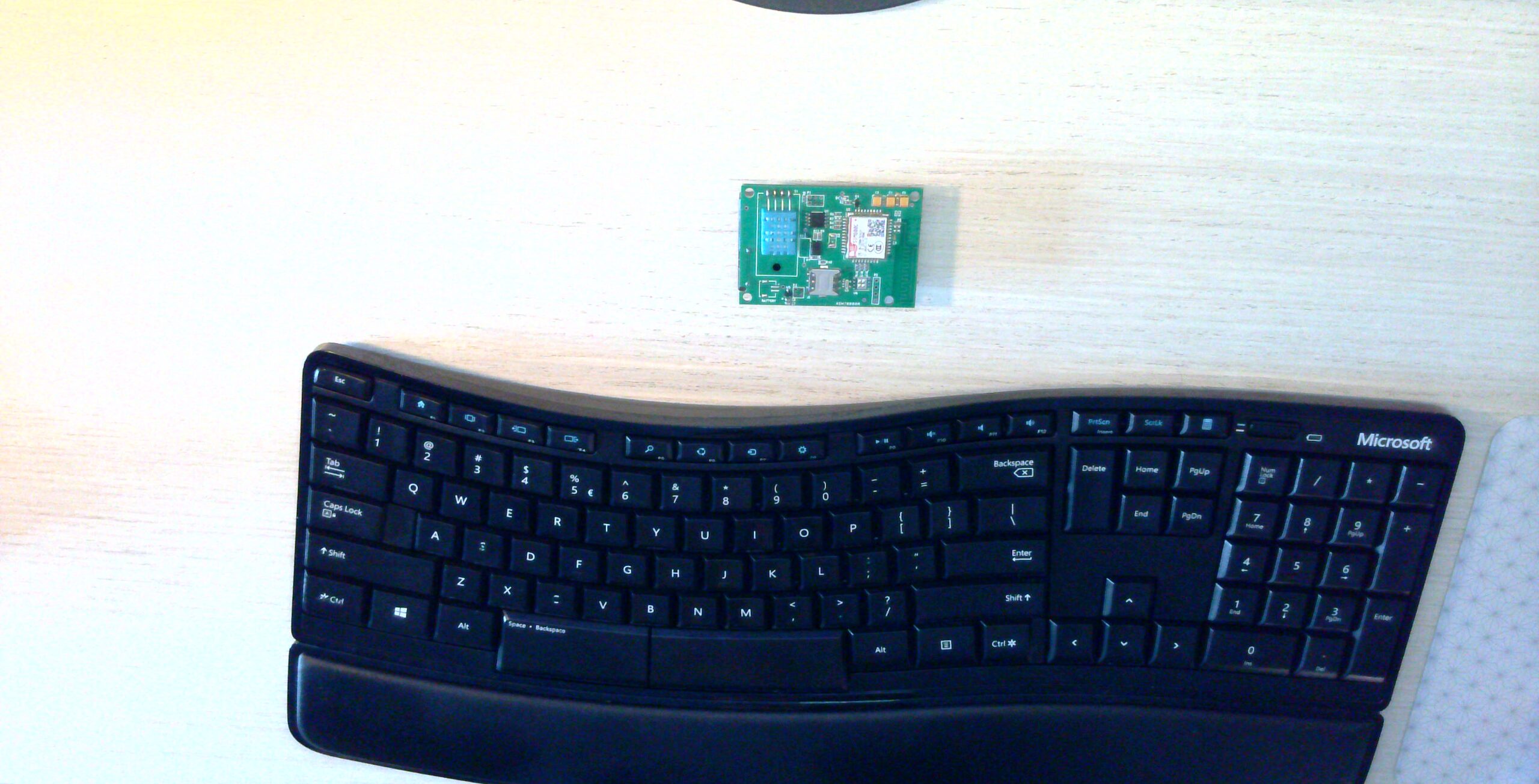
In today’s remote work landscape, having a good webcam is crucial. While your laptop’s built-in camera might get the job done, investing in a quality webcam can significantly enhance your online presence. The BenQ ideaCam S1 Plus may be the perfect upgrade you’re searching for.
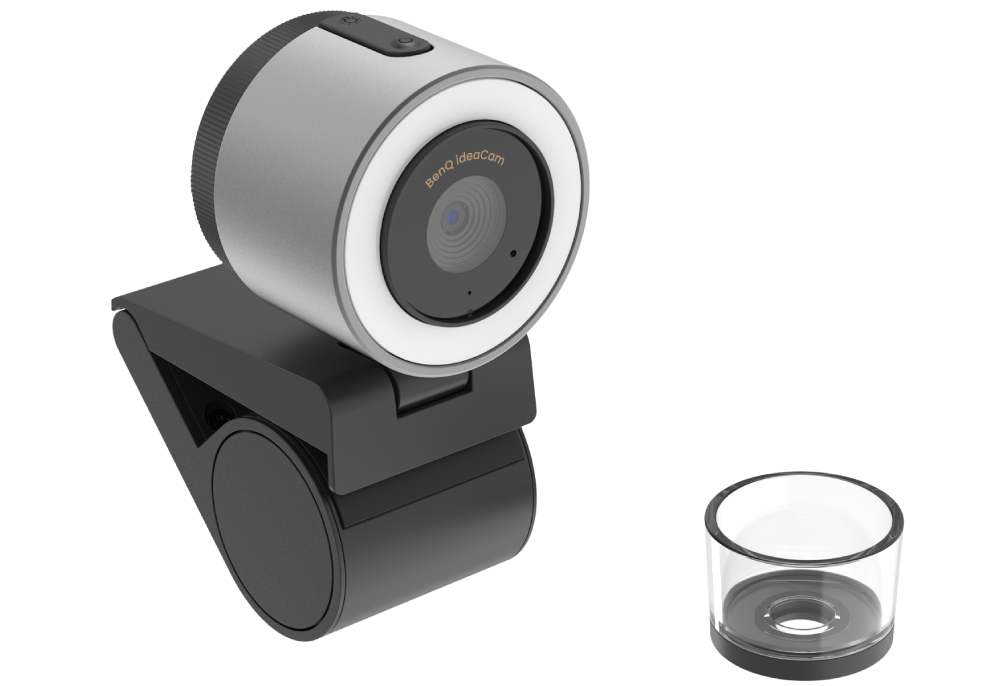
The camera is built around a Sony8MP sensor and includes a range of unique functionalities that your typical laptop camera or a generic webcam would not have like a document camera mode, auto-rotate, smartfocus, dual image style, and a remarkable 15x macro lens ideal for detailed electronic projects or tasks requiring high magnification. Additionally, it is equipped with a noise-canceling microphone to enhance audio quality in noisy environments. The design also incorporates a tripodmount, providing versatile setup options either on a tripod or directly on a table for added flexibility. Now that we know a little bit more about the features of this device.
Unboxing
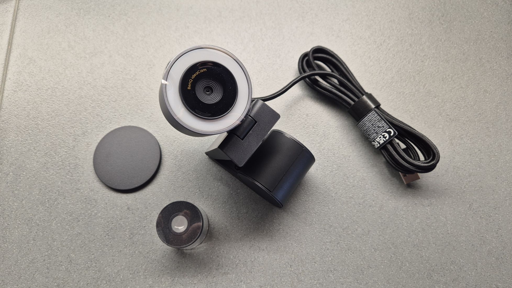
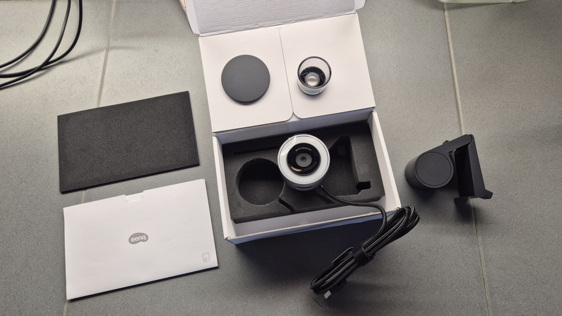
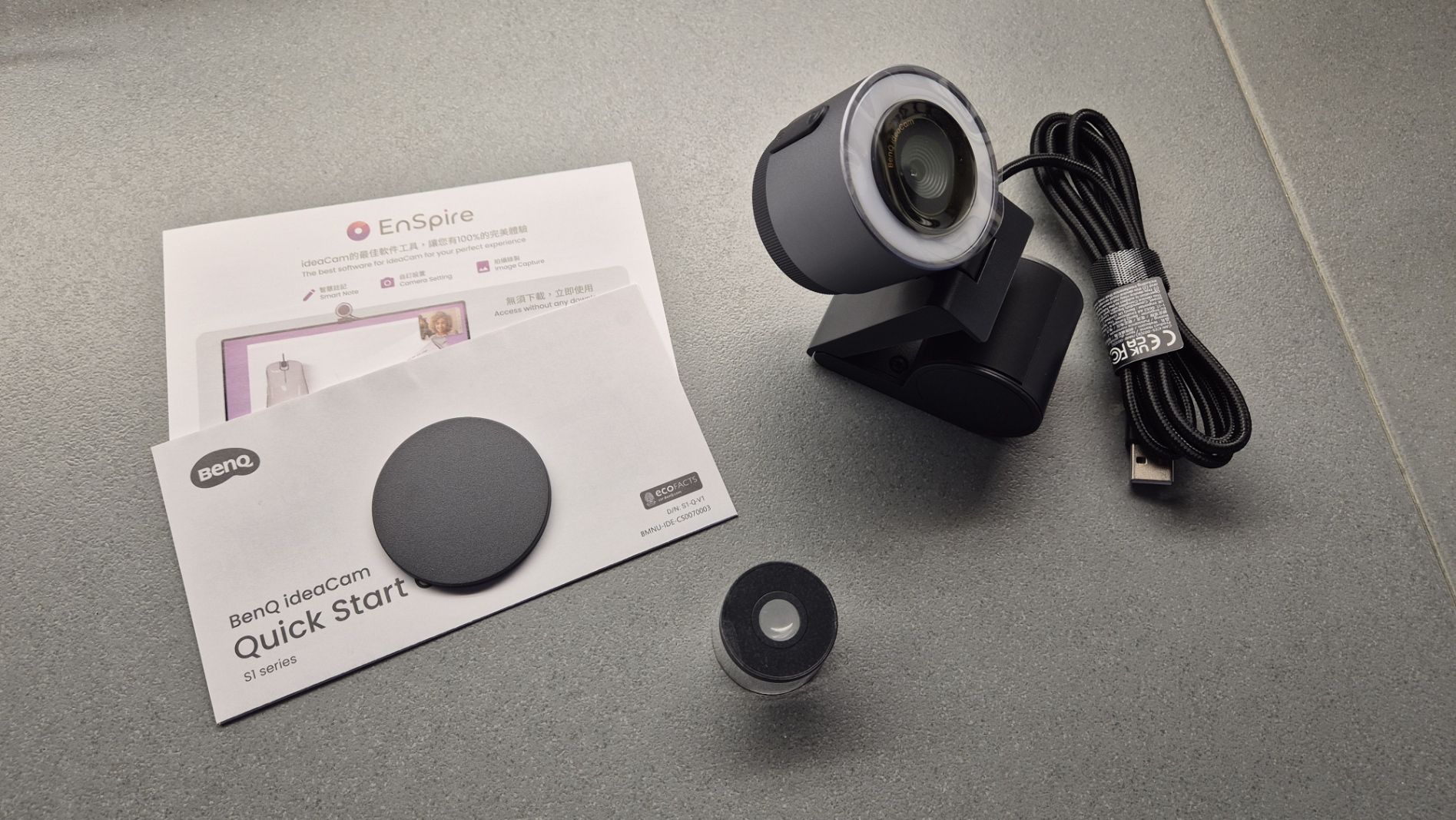
BenQ ideaCam S1 Plus box with accessories
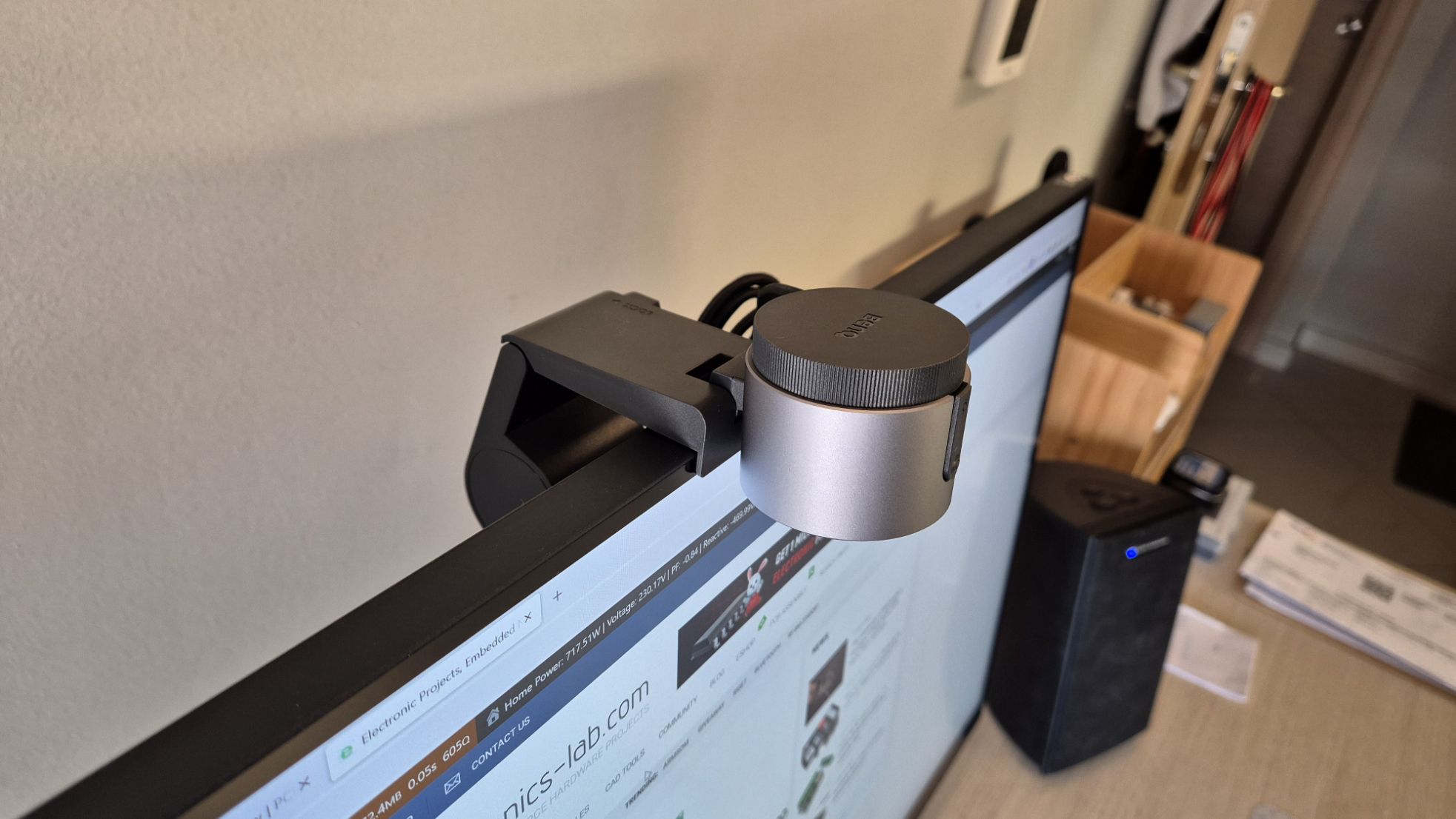
The box includes the essential parts to get you started right away. Inside you can find the camera, the monitor stand, the macro lens, a protection cup, and documentation. So, to start you just have to place the camera on its base and place it on top of your monitor. The base is heavy enough to keep the camera steady and attached to the monitor, regardless of cable movement or other vibrations.
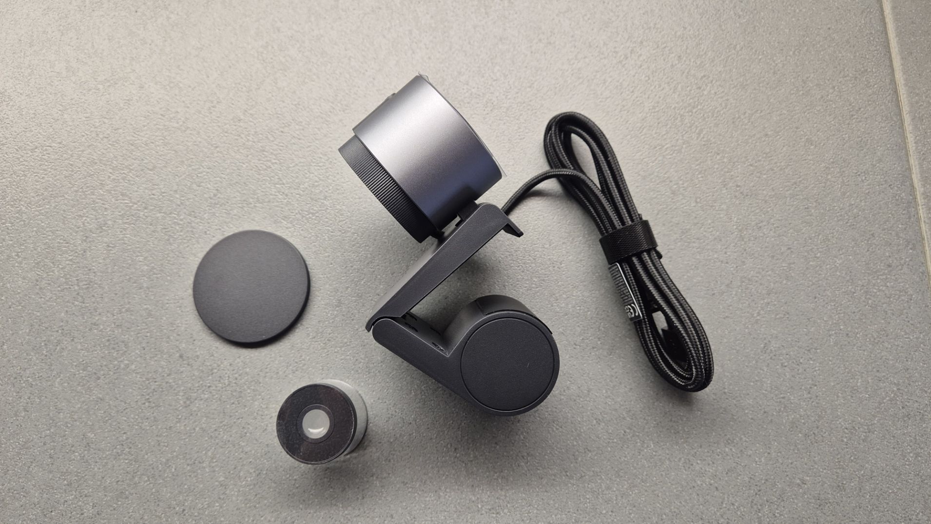
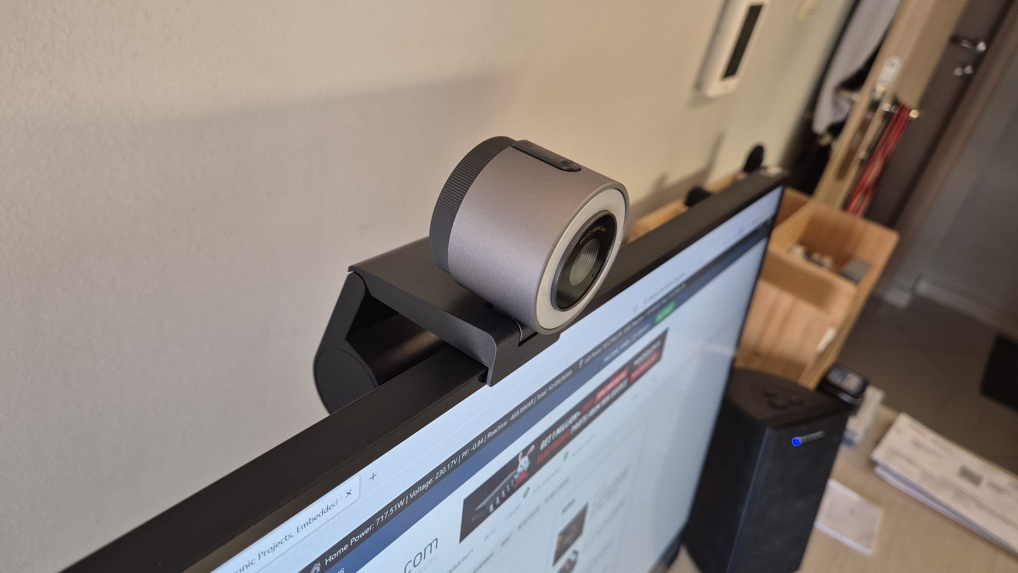
camera attached to the base – side viewcamera attached to the base – front view
First Impressions
At first look, the ideaCam S1 Plus looks great and combines a Macro Webcam and a Webcam for Demonstration in a simple design. The camera is small enough to fit nicely on your desk without taking up too much space. The camera features a silvery gray color with a black top and bottom cover that will go along well with any desk setup. There is a back and front panel for the camera which are both made out of plastic which feels a little cheap but I think it’s ok for this price point. The front cover is magnetic and also works as a privacy cover that is useful for keeping things private when you’re not using the camera. Overall, the build quality of the ideaCam S1 Plus is similar to other webcams in its price range.
Specifications
As mentioned earlier the camera is equipped with an 8MP Sonysensor, with a wide f/2.0 aperture. With that spec, the max resolution of this camera is 3264x2448p which means it can stream a 4K video seamlessly and take photos in 4K resolutions. As this is a Sony sensor the camera can deliver a decent performance, in a well-lit condition. From our experience with this camera, we can say that it may struggle in low-light conditions, with noise appearing on the image. Here comes the ring light in front that can illuminate the surrounding area very clearly, especially in macro mode.
camera attached to the monitor
The camera module includes a handy hinge that lets you tilt it down to your desk, especially useful if it’s mounted on top of your monitor. While many cheaper cameras might struggle with this setup, this camera excels thanks to its autofocus and auto-rotate features. It not only shifts focus automatically to whatever’s on your desk but also rotates the image to keep it upright, making sure everything looks right to the viewer without any extra hassle.
camera attached to the monitor in presentation modecamera attached to monitor in Portrait view
Smart Focus
The camera also comes with a Smart Focus mode. In this mode, the ideaCam automatically adjusts the focus when switched to desk view, ensuring documents are displayed clearly. Additionally, it features a Dual Image Style mode that automatically toggles between two settings: Portrait Mode, which enhances facial features for video conferences, and Instant Demonstration Mode, which prioritizes clarity and detail for object shooting. This adaptability makes the camera versatile and improves the user experience for various tasks.
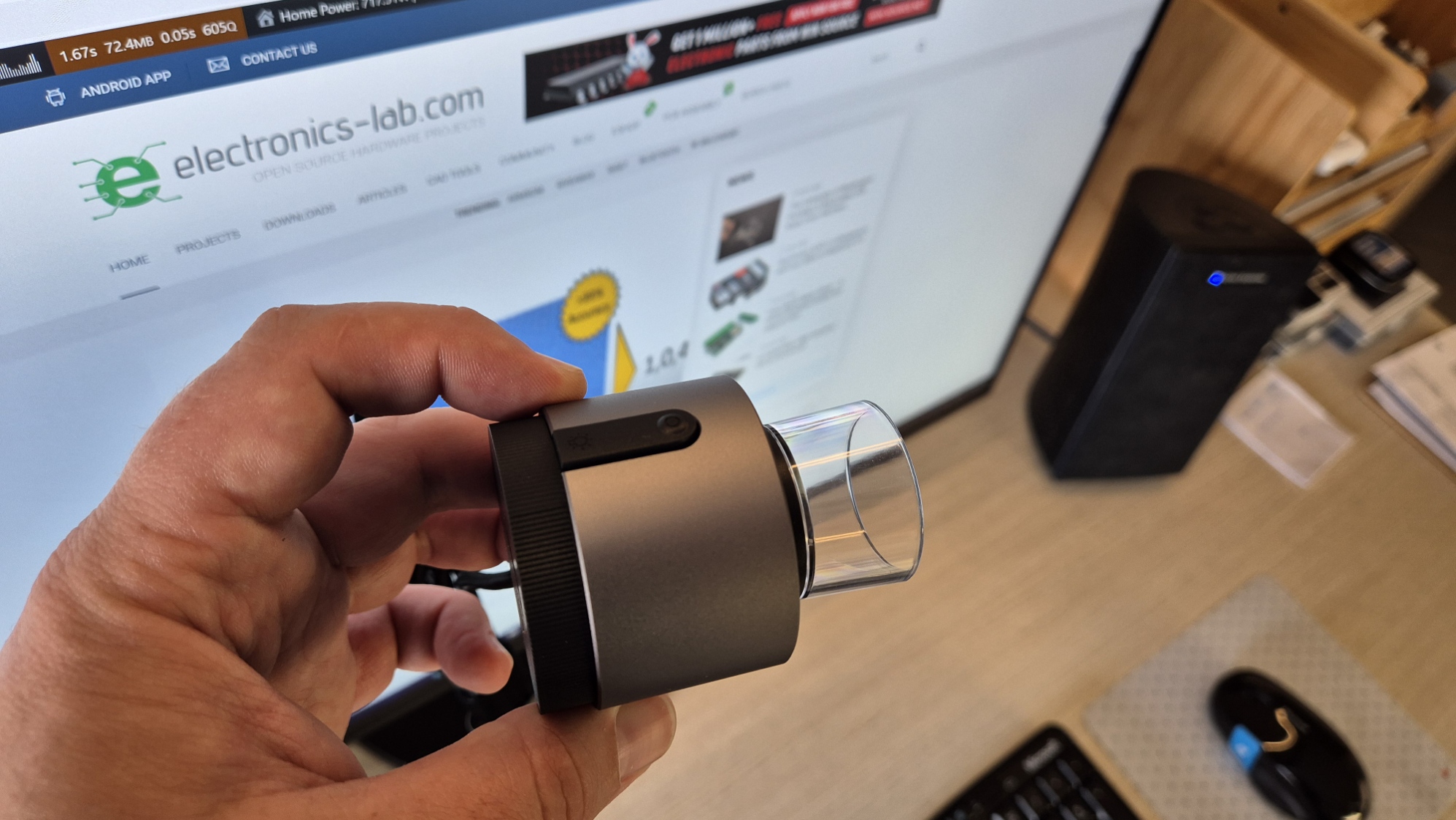
camera with the macro lens attached
Macro Lens
The package includes a 15X magnifying zoom lens that effectively turns your standard webcam into a useful microscope. This feature is great for closely examining small objects. It’s especially beneficial for engineering professionals who work with electronics and hardware, as it enhances their ability to inspect details minutely.
Photo Snapshot without the macro lensPhoto Snapshot with the macro lens attachedPhoto Snapshot with the macro lens attached
Noise Canceling Microphone
The ideaCam S1 Plus comes with an advanced noise-canceling microphone that uses AI technology to eliminate background noise, making your voice clearer during calls. This feature is incredibly useful in loud environments, ensuring that your communications remain clear and uninterrupted.
Function Buttons
The ideaCam S1 Plus also includes a convenient freeze button feature, which allows you to pause the video feed instantly. This is particularly useful during presentations or demonstrations where you need to hold a specific image on screen while discussing it. The freeze function ensures that viewers can focus on the details without missing any critical information, enhancing both the effectiveness and professionalism of your communications. Whether for educational purposes or collaborative projects, this feature adds a layer of control and interaction to your video sessions.
Demo Video
Sample Captures
Software
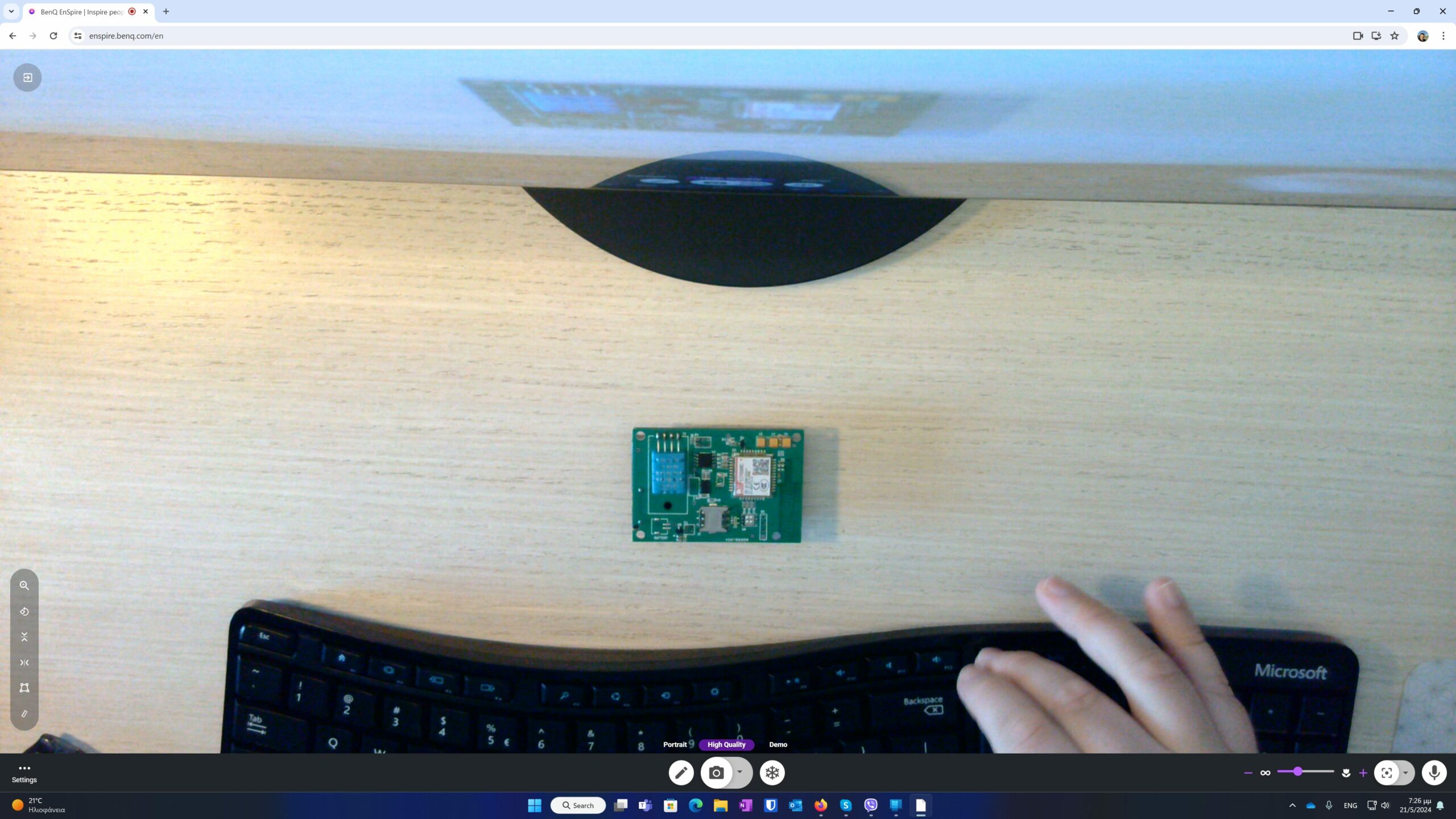
Like other cameras, this one is plug-and-play, which means you don’t need to install any additional drivers or software to fully utilize the camera’s capabilities. The camera works right away in your browser or you can download the available PC or Mac application.
Screenshot of the Chrome camera interface
Conclusions
Overall, the BenQ ideaCam S1 Plus blends standard webcam functions with the features of a document camera. It offers flexible shooting modes, macro capabilities, and smart autofocus, making it a strong contender in the sub $200 price range.
Purchase
The BenQ ideaCam S1 Plus is available for purchase on Amazon.com for ~$200 + shipping.
Firmware Update (24/07/2024)
They have significantly increased the focus speed of ideaCam by 50% compared to the old version. This improvement is designed to provide a smoother and more efficient user experience, ensuring you capture your ideas more effectively.
Enspire Win Downloaded Version
They have introduced a new feature that allows you to use the remote control (photo button) to open the Enspire software. This addition aims to simplify your workflow and enhance the usability of Enspire offline.
Important Information for Windows and Mac Users
Once you open the downloaded version of Enspire, you will see a notification reminding you of these updates. Additionally, there will be an OTA (Over-The-Air) update for Enspire. We also want to remind you that you can get a more comprehensive experience with the downloaded version instead of the online version.
For Mac users, the new version is scheduled to be released at the end of July. We will keep you updated and notify you as soon as it is available.
Action Required
To enhance your experience, please kindly update the firmware and download the latest version of Enspire: https://benqurl.biz/3pO1Eu3
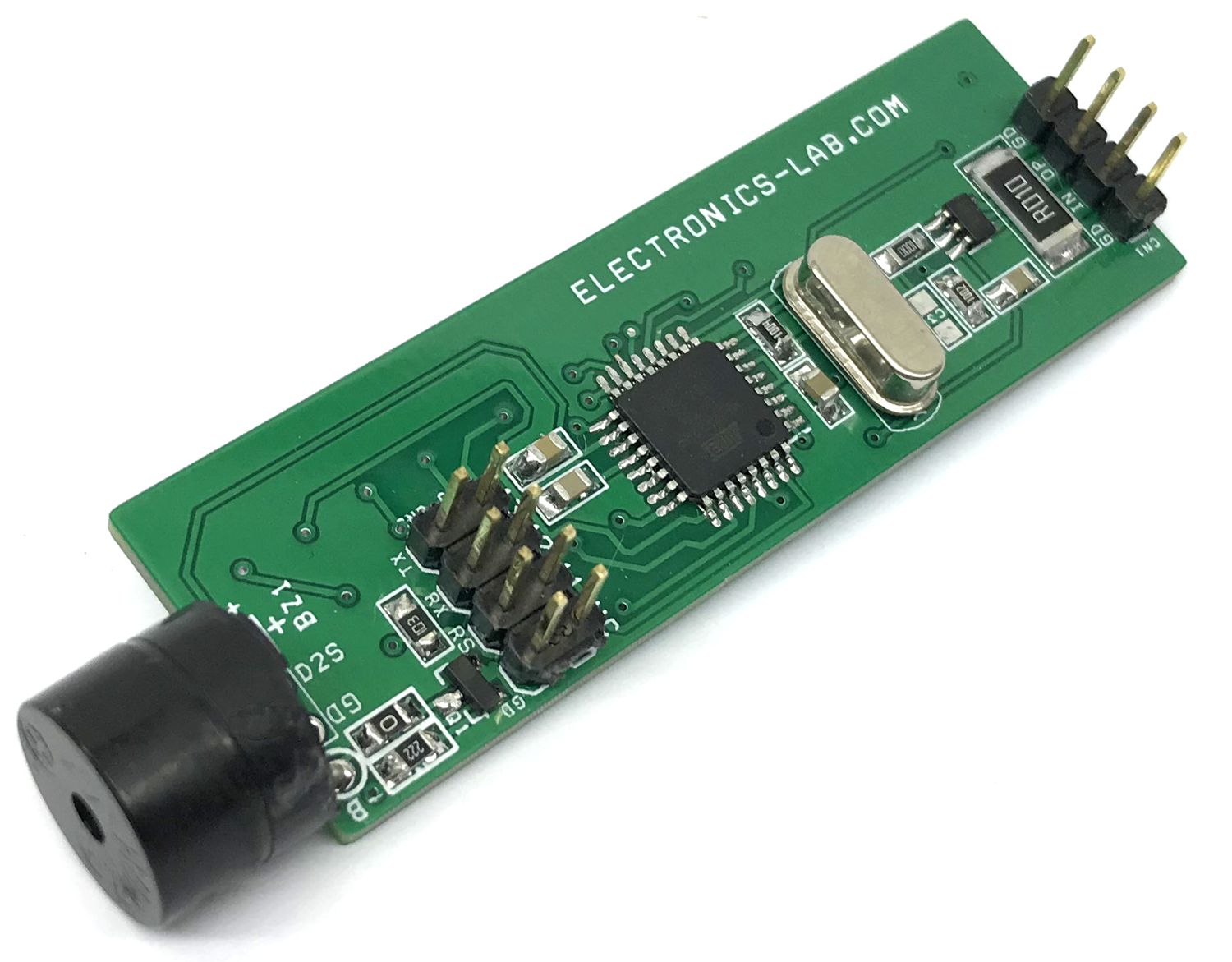
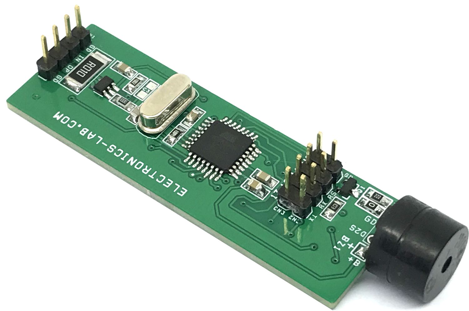
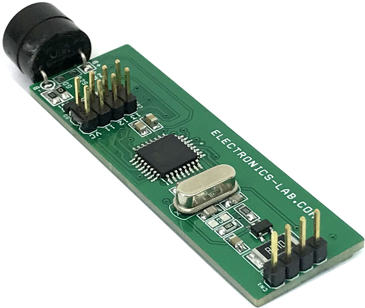
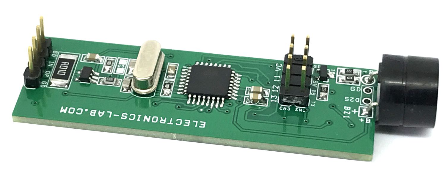
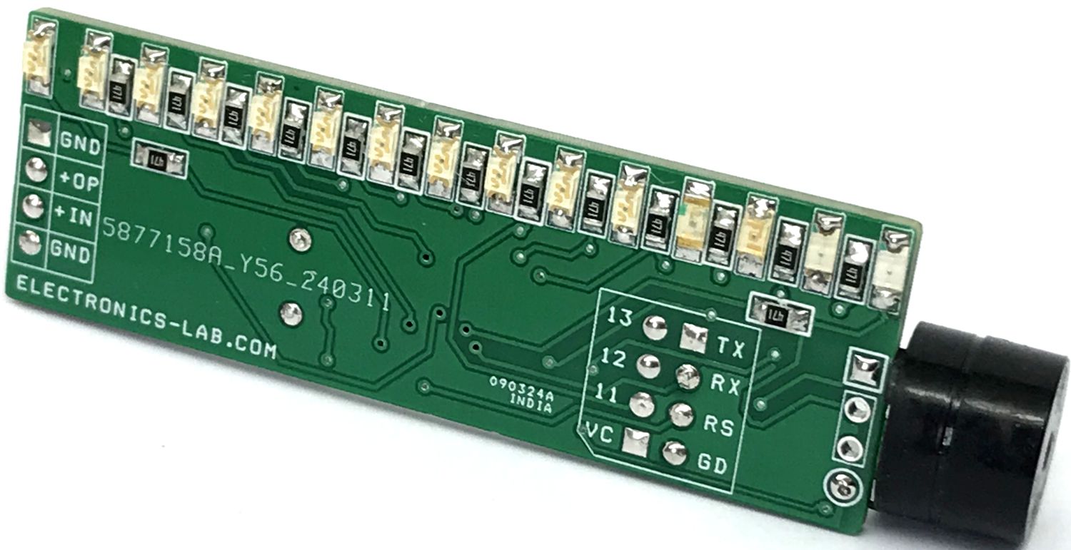
This Bar-Graph Display provides a high visibility 15-Segment Bar-Graph display for current measurements. A buzzer provides audible sound when an over-current condition event occurs. The 15 segments are made with Red, Blue, Green, and yellow color LEDS. All LEDs are SMD size 1206. This tiny board can display 0 to 2A current and provide an Alarm sound when the current level goes more than 2A. The project is Arduino-compatible and is based on an ATMEGA328 chip. INA198 chip measures the load current across the shunt resistor and provides an output voltage to ADC of ATMEGA328. The microcontroller drives and controls the 15 LEDs connected to I/O lines.
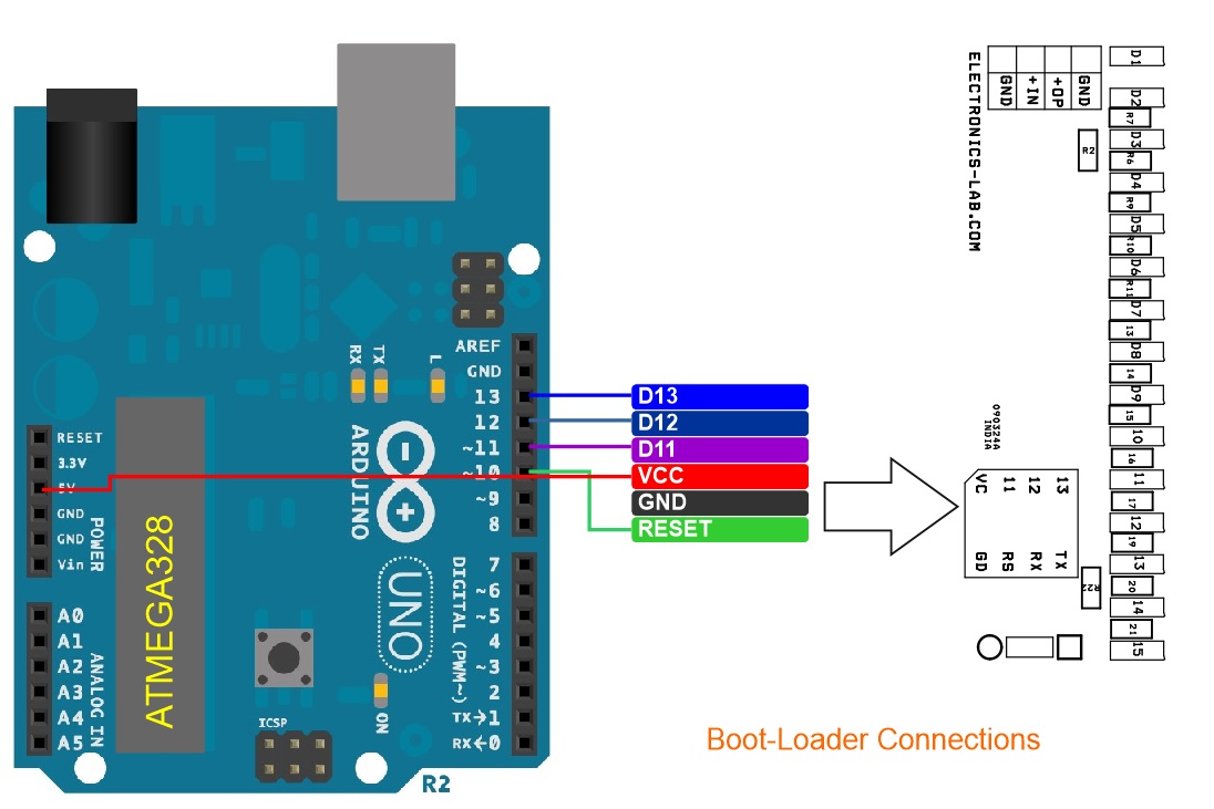
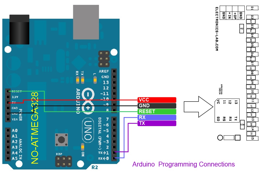
The project is Arduino-compatible. Connectors CN2 and CN3 are provided for Arduino programming and boot-loader. An example Arduino code is available as a download. Users may modify and write their code. Refer to the diagrams below for Bootloader and Arduino programming connection. Each LED display consumes approx. 125mA current and the ADC Map values to 15Leds + Buzzer.
Note: Arduino code is written to measure 2A current. The project can support a higher or lower current range, by changing the value of the shunt resistor. A higher or lower current range can be achieved. Please read the datasheet of INA198 for more info.
Arduino Pins: Buzzer A5, Analog Current Sense Input = A0
Bar-Graph LED Vs Arduino Pins: LED 1 = D3, LED 2 = D5, LED 3 = D4, LED 4 = D6, LED 5 = D7, LED 6 = D8, LED 7 = D9, LED 8 = D10, LED 9 = D11, LED 10 = D12, LED 11 = D13, LED 12 = A1, LED 13 = A2, LED 14, A3, LED 15 = D2
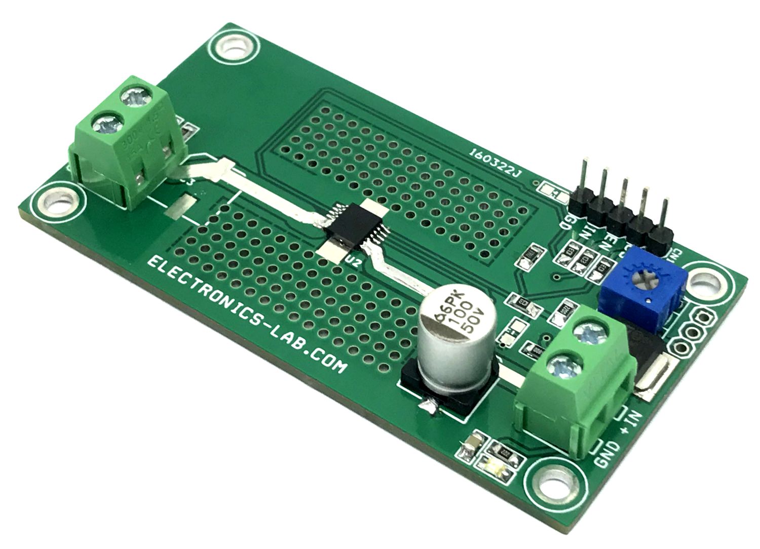
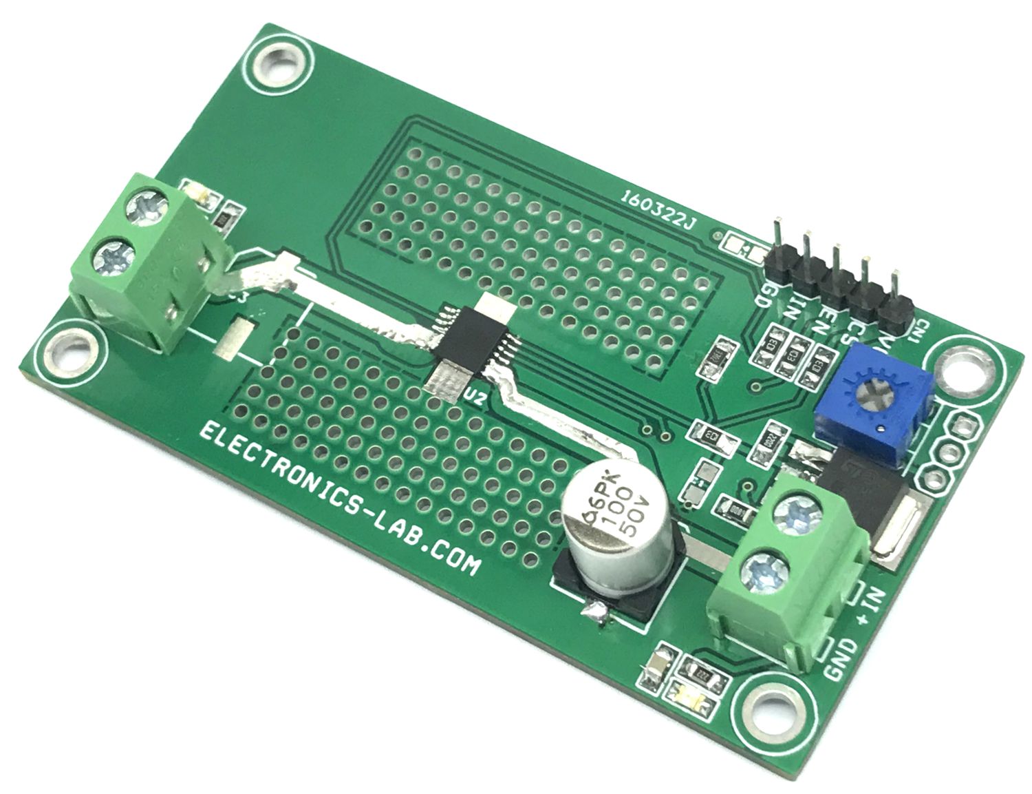
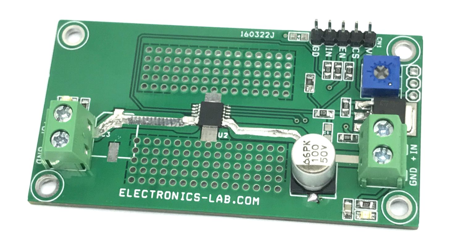
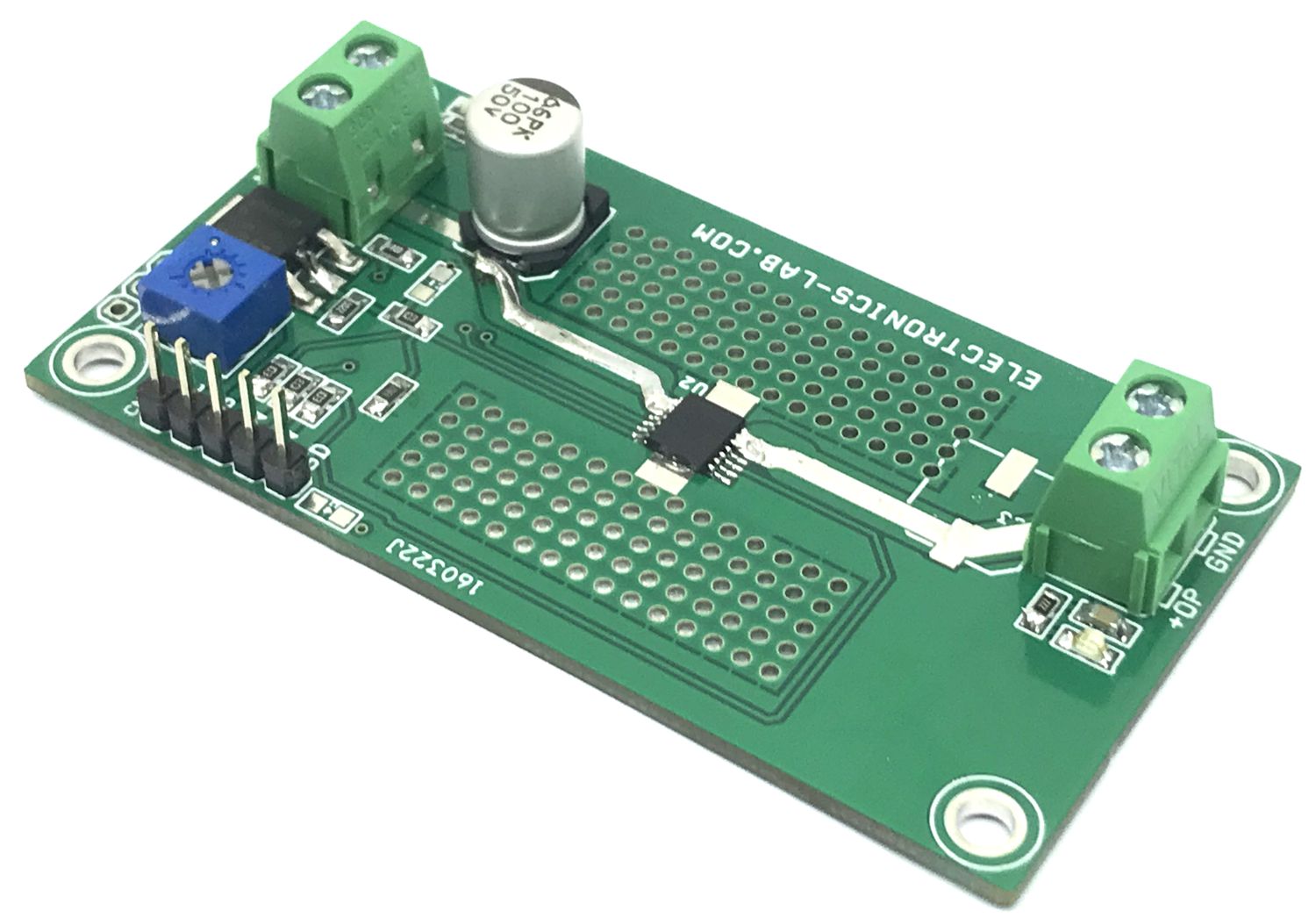
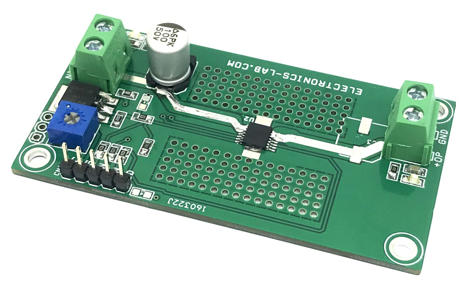
This is a single-channel, fully-protected, high-side power switch with programmable current-limit. Full diagnostics and high-accuracy current-sense features enable intelligent control of the load. A programmable current-limit function greatly improves the reliability of the whole system. High-accuracy current sensing allows a better real-time monitoring effect and more-accurate diagnostics without further calibration. A current mirror is used to source 1/K of the load current, which is reflected as voltage on the CS pin. K is a constant value across the temperature and supply voltage. The current sensing function operates normally within a wide linear region from 0 to 4 V. The CS pin can also report a fault by pulling up the voltage of the Vs active drain and a source voltage clamp is built in to address switching off the energy of inductive loads, such as relays, solenoids, pumps, motors, and so forth. During the inductive switching-off cycle, both the energy of the power supply (EBAT) and the load (ELOAD) are dissipated on the high-side power switch itself. With the benefits of process technology and excellent IC layout, the TPS1H100BQ-Q1 device can achieve excellent power dissipation capacity. When a fault condition occurs, CS works as a diagnostics report pin. When an open load or short to battery occurs in the on-state, VCS almost equals 0. When the current limit, thermal shutdown/swing, open load, or short to battery in the off-state occurs, the voltage is pulled up to VCS.
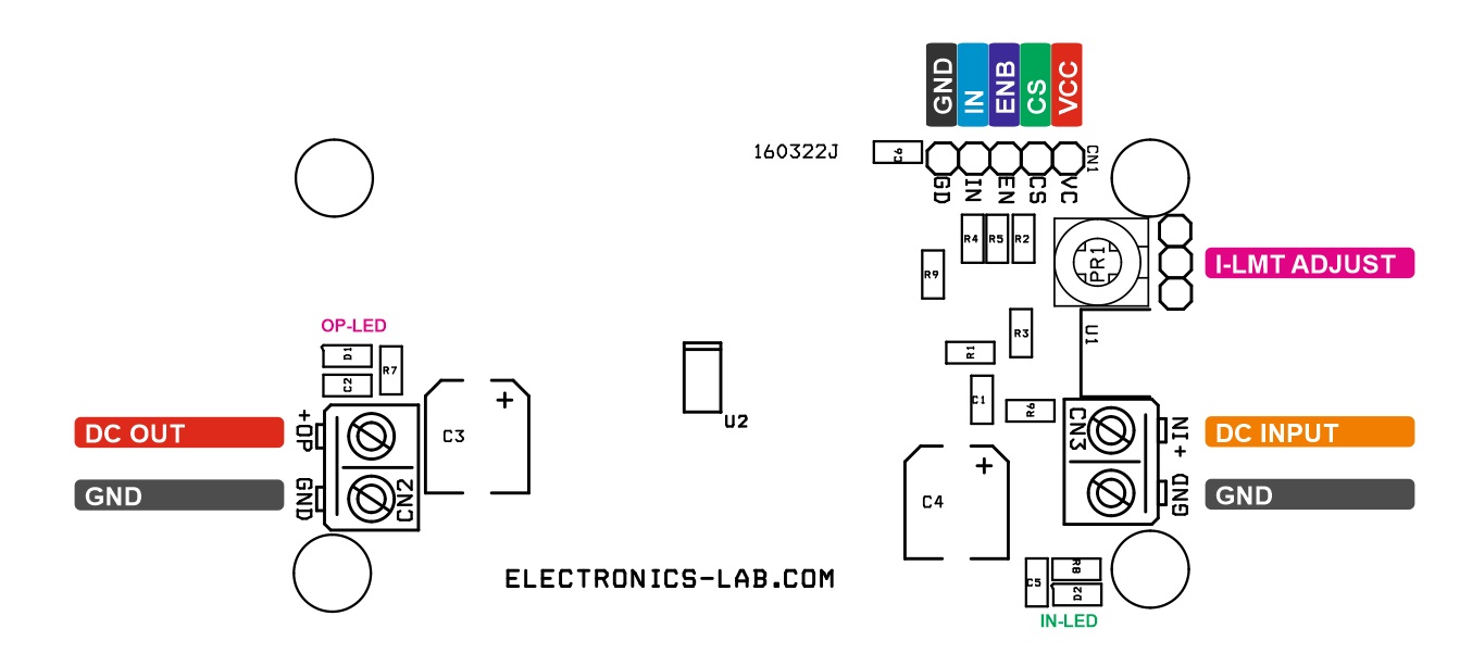
The project can be used as a high-side power switch for a wide variety of resistive, inductive, and capacitive loads, including low-wattage bulbs, LEDs, relays, solenoids, and heaters. CL (Current Limit) resistor can be changed through PR1 Trimmer potentiometer. When PR1 is 0 Ohm there is no external current limit function and the internal current limit is active. This current limit value is around 0.5A.
Features
Operating voltage 5 to 37V (Limited Due to L317 Input Supply)
Current Limit Adjustable 0.5A to 5Amps (PR1 Trimmer Potentiometer)
Operating junction temperature: –40ºC to 150ºC
Very-low standby current: <1 µA
Microcontroller input control: 3.3-V and 5-V logic compatible
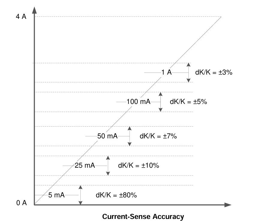
High-accuracy current sense – Analog current output as a ratio of the output current (3% at nominal load and 20% at light load)
Programmable current limit with external Trimmer Potentiometer PR1
High-accuracy current sense, ±30 mA at 1 A, ±4 mA at 5 mA
PCB Dimensions 73.50 x 39.05 mm
4 x 3 mm Mounting Holes
Protection:
Short-circuit protection
Overvoltage protection,
Thermal shutdown/swing with self-recovery
Loss of GND,
loss of Vs protection– ESD protection
Diagnostic:
On/off state output open/short to battery detection
Overload and short-to-ground detection and power limiting
Thermal shutdown/swing diagnostic
Current-sense analog diagnostic
Diagnostic enable function for multiplexing of MCU analog or digital port
The TPS1H100-Q1 device is a fully protected high-side power switch, with integrated NMOS power FET and charge pump, targeted for the intelligent control of the variable kinds of resistive, inductive, and capacitive loads. Accurate current sense and programmable current limit features differentiate it from the market.
Accurate Current Sense
High-accuracy current sense signal allows better real-time monitoring of effects and more accurate diagnostics without further calibration. It provides the real-time output current monitoring. Accurate Current mirror is used to source 1/K of the load current, and reflected as VCS=ICS×RCS. Voltage level at CS pin is maintend within limit of 0 to 4V for normal operations Also, when a fault condition happens, it works as a diagnostics report pin. When an open load/short to battery event happens in on-state, VCS almost equals to 0. When a current limit, thermal shutdown/swing, open load/short to battery event in off-state happens, the voltage is clamped at VCS, H
Applications
High-side relay driver
High-voltage power switch for submodule power supply
Low-wattage lamp driver
General resistive, inductive, and capacitive loads
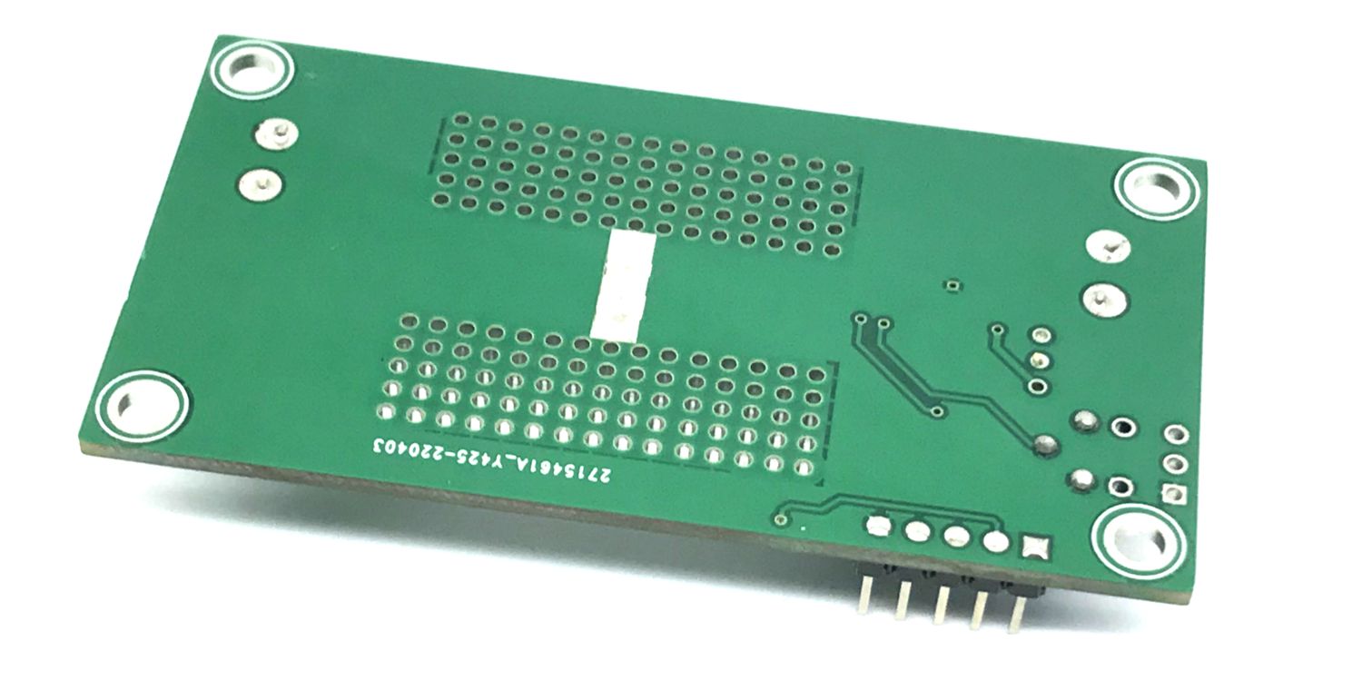
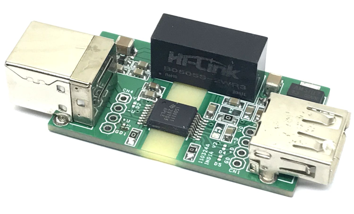
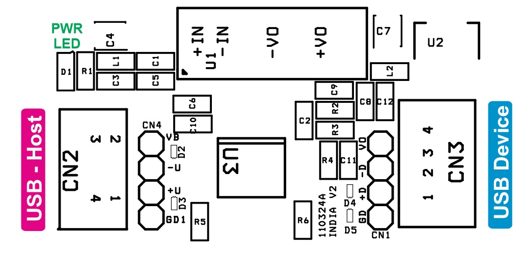
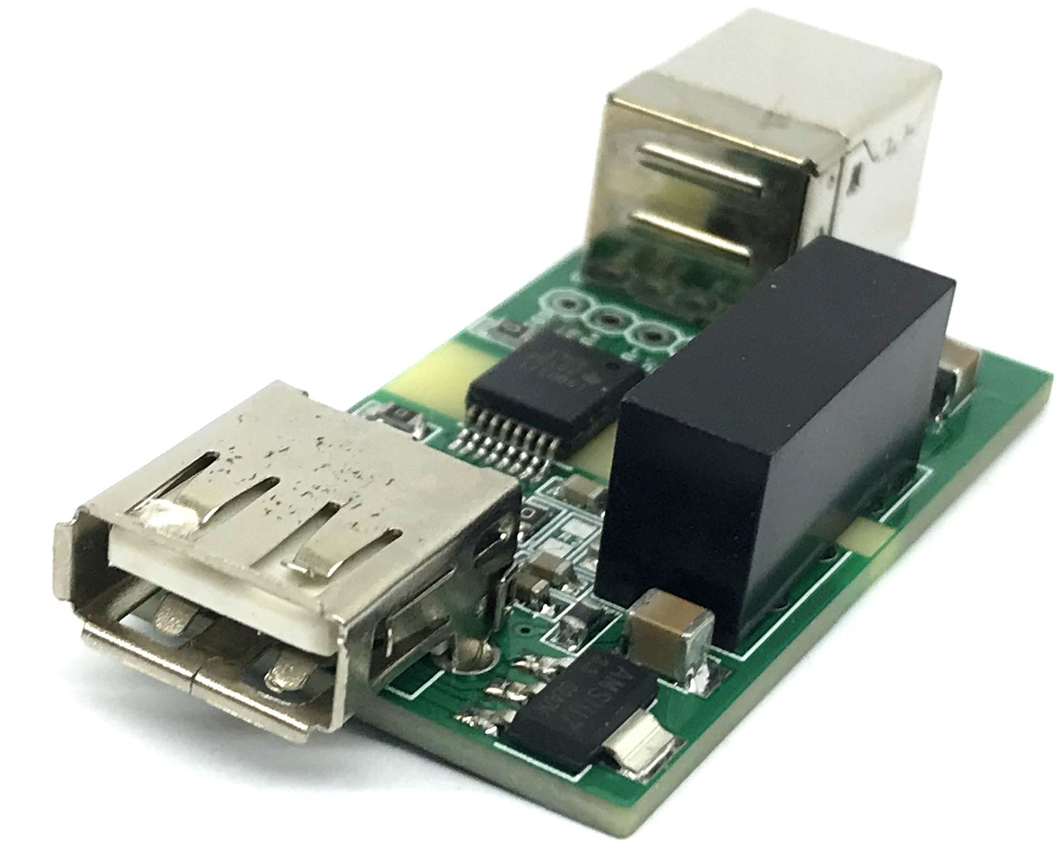
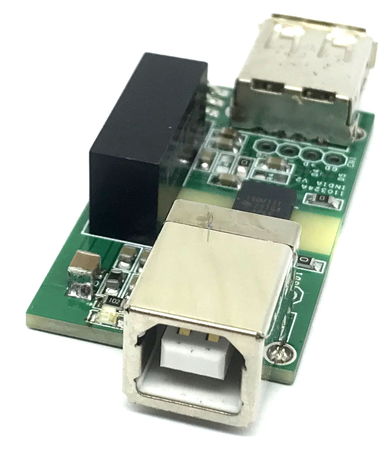
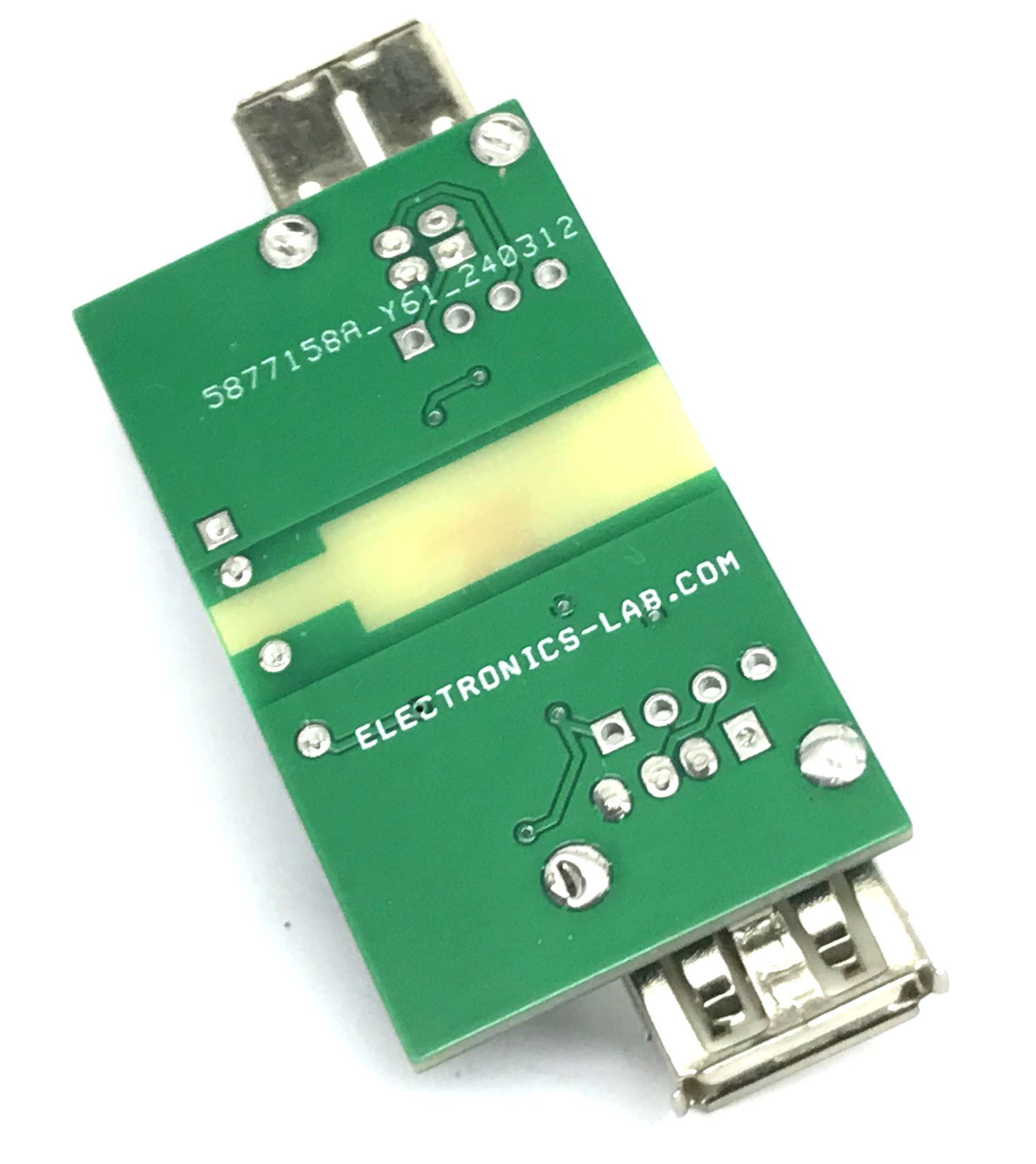
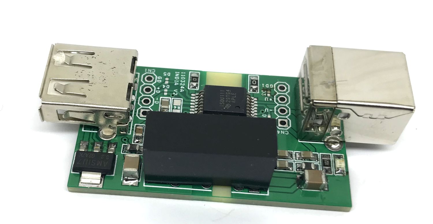
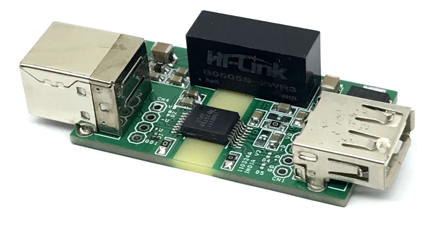
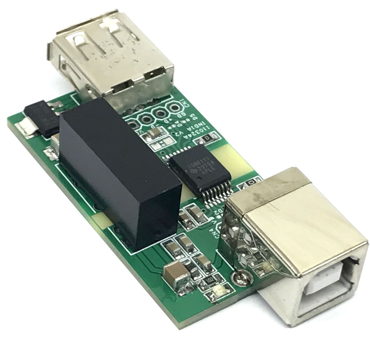
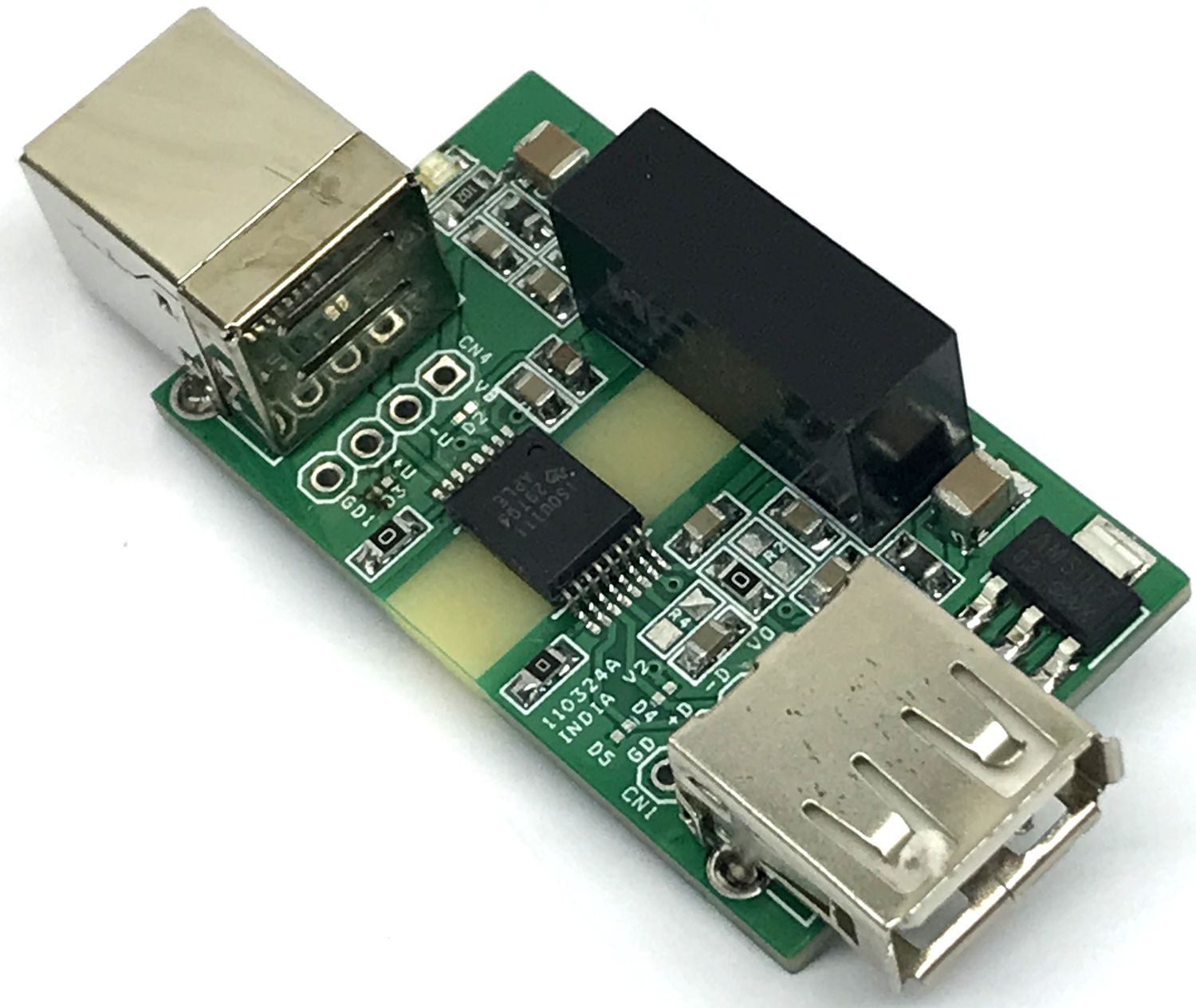
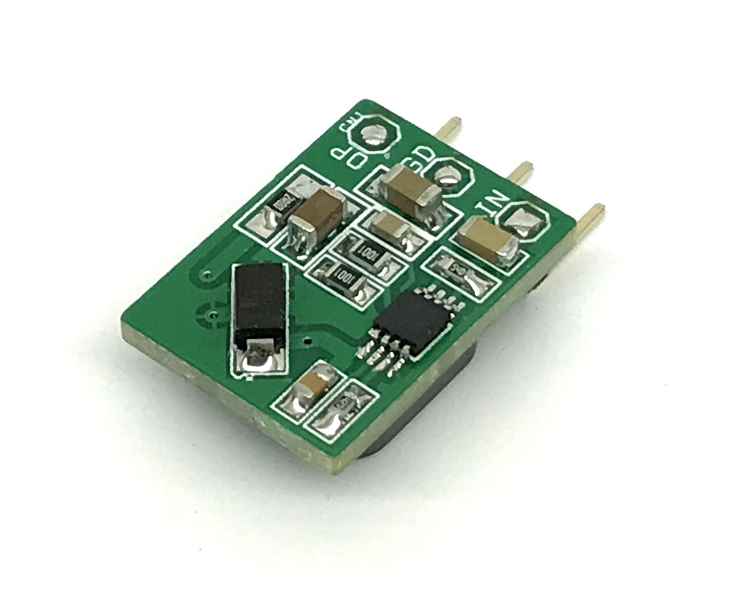
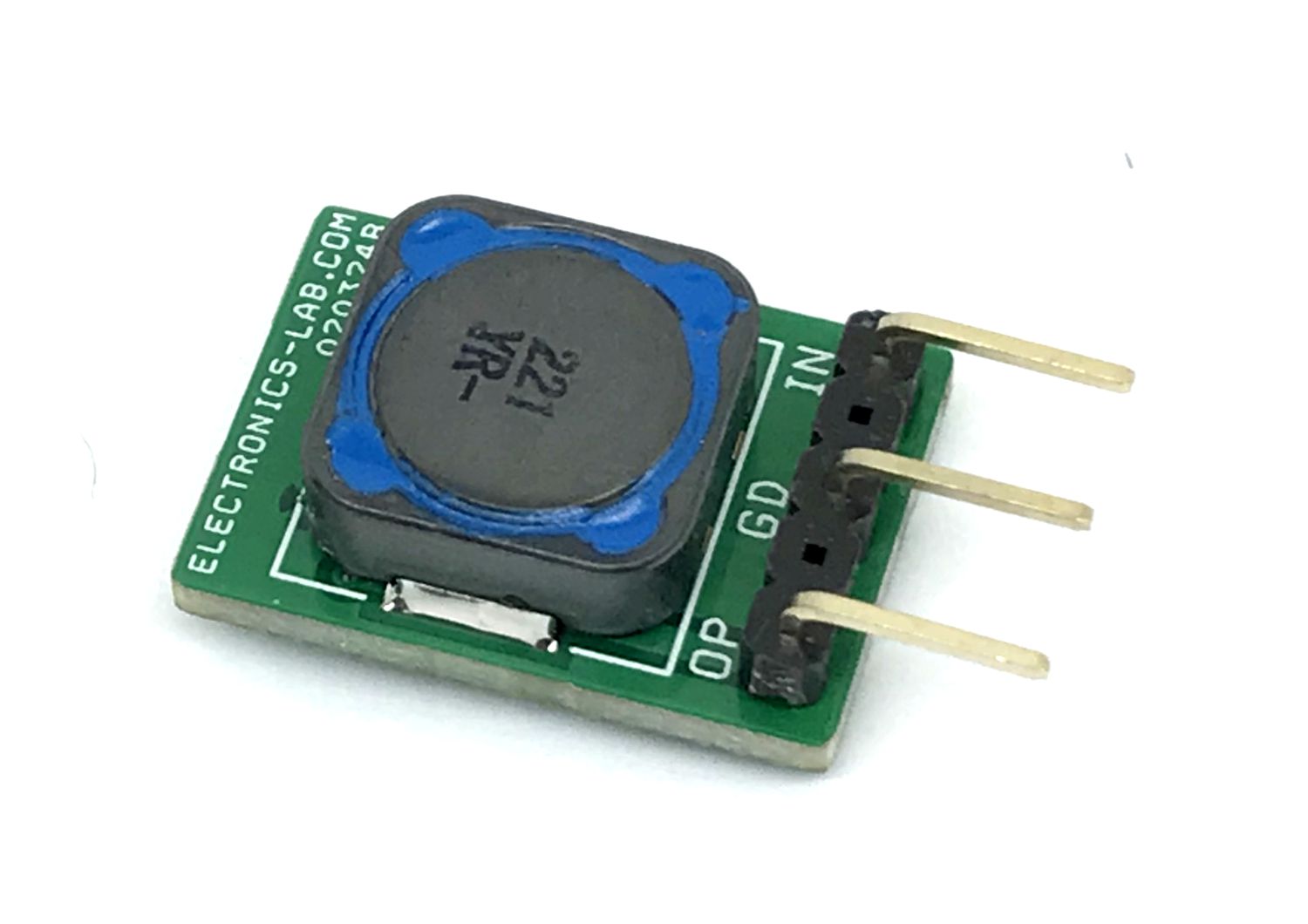
The project presented here is a USB port-powered, USB 2.0 isolator that isolates the USB host and USB device. It is a galvanically-isolated USB2.0 repeater, that supports low speed 1.5Mbps, and full speed 12Mbps communication. The project automatically connects and detects the bus speed. This USB 2.0 isolator is efficiently powered from the USB port and requires no external power, on board isolated DC-DC converter U1 provides 5V to the other side of the circuitry and USB port. U2 LDO provides 3.3V to the chip. L1 and L2 ferrite beads take care of noise immunity on the DC bus. The project protects the host USB port from noise and high voltage.
Note: Output USB Connector CN3 can supply 5V to an external USB device, DC-DC converter can output a maximum 400mA. The user must take care not to overload the Output of the USB Power, the load has to be within 400mA. The output of USB is isolated and continuously protected from short circuits.
Features
Compliant to USB 2.0
Supports low speed (1.5 Mbps) and full speed (12 Mbps) signaling
Automatic speed and connection detection
Supports L1 (sleep) and L2 (suspend) low-power states
Supports automatic role reversal for USB On-The-Go (OTG) and Type-C® Dual Role Port (DRP) designs
VBUS voltage range: 4.25 V to 5.5 V (Power Supply from USB Port)
Meets CISPR32 class B emissions limits
Ambient temperature range: –40°C to +125°C
Safety-related certifications:
7071-VPK VIOTM and 2121-VPK VIORM (Reinforced) per DIN EN IEC 60747-17 (VDE 0884-17)
5000-VRMS isolation for 1 minute per UL 1577
IEC 62368-1, IEC 60601-1 and IEC 61010-1 certifications
CQC, TUV, and CSA certifications
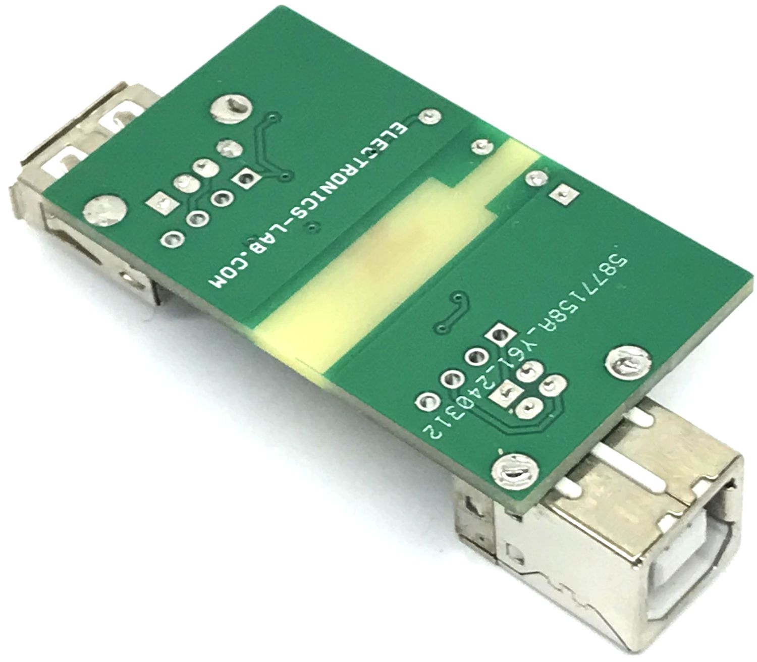
PCB Dimensions 44.77 x 25.72 mm
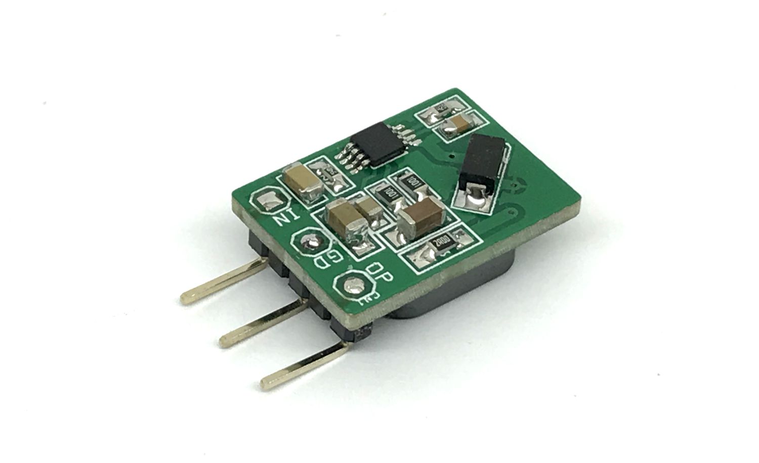
Features of DC-DC Converter
Continuous short-circuit protection
Input 5V DC
Output 5V DC
Maximum Load Current 400mA
No-load input current as low as 8mA
Operating ambient temperature range: -40℃to +105℃
High efficiency up to 86%
High power density
I/O isolation test voltage1.5kVDC
The ISOUSB111 is a galvanically-isolated USB 2.0 compliant repeater supporting low speed (1.5 Mbps) and full speed (12 Mbps) signaling rates. The device supports automatic connect and speed detection, reflection of pull-ups/pull-downs, and link power management allowing drop-in USB hub, host, peripheral, and cable isolation. The device also supports automatic role reversal – if after disconnect, a new connect is detected on the Upstream facing port, then the Upstream and Downstream port definitions are reversed. This feature enables the device to support USB On-The-Go (OTG) and Type-C Dual Role Port (DRP) implementations. This device uses a silicon dioxide (SiO2) insulation barrier with a withstand voltage of up to 5000 VRMS and a working voltage of 1500 VRMS. Used in conjunction with isolated power supplies, the device protects against high voltage and prevents noise currents from the bus from entering the local ground. The ISOUSB111 device is available for reinforced isolation. It supports a wide ambient temperature range of –40°C to +125°C.
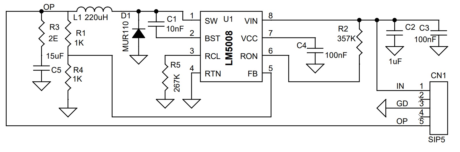
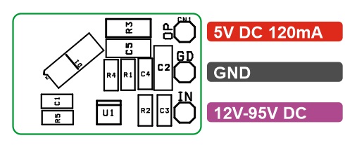
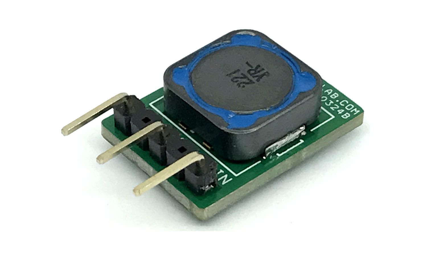
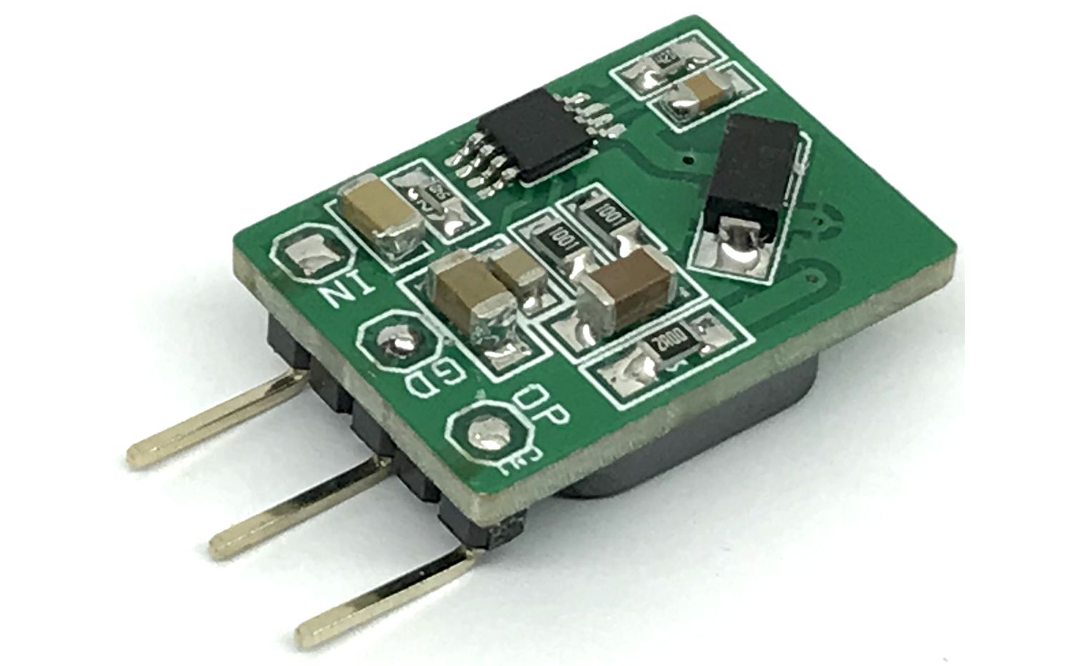
This is a versatile synchronous buck DC/DC converter built using the LM5008 chip. The operating input voltage range is 12V to 95V DC, providing 5V/120-350mA output. The regulator can provide a load current of up to 350mA, but it’s advisable to draw only 120mA due to the small thermal area on PCB (small PCB). The default output of the converter is set to 5V. Output is adjustable by changing the feedback resistor values R1 and R4. Please refer to the datasheet of the LM5008 chip for more info.
Features
Operating Input Voltage Range of 12 V to 95 V
Output 5V @ 120mA (Output Up to 350mA with fan)
High Efficiency Operation
Adaptive Constant On-Time Control Architecture
Ultra-Fast Transient Response
No Control Loop Compensation Required
Nearly Constant Switching Frequency
PWM On-Time Varies Inversely with Input Voltage
Low Input Quiescent Current
Inherent Protection Features for Robust Design
Intelligent Current Limit Protection
VCC and Gate Drive UVLO Protection
Thermal Shutdown Protection with Hysteresis
PCB Dimensions 20.64 x 14.92MM
The LM5008 350-mA step-down switching converter features all of the functions needed to implement a low-cost and efficient buck regulator. This high-voltage converter has an integrated 100-V N-channel buck switch and operates over an input voltage range of 9 V to 95 V. The device is easy to implement and is provided in the 8-pin VSSOP and the thermally enhanced 8-pin WSON packages. The converter uses a hysteretic control scheme with a PWM on-time inversely proportional to VIN. This feature allows the operating frequency to remain relatively constant. The hysteretic control requires no loop compensation. An intelligent current limit is implemented with forced off-time, which is inversely proportional to VOUT. This scheme ensures short-circuit protection while providing minimum foldback. Other protection features include: thermal shutdown, VCC undervoltage lockout, gate drive undervoltage lockout, and maximum duty cycle limiter.
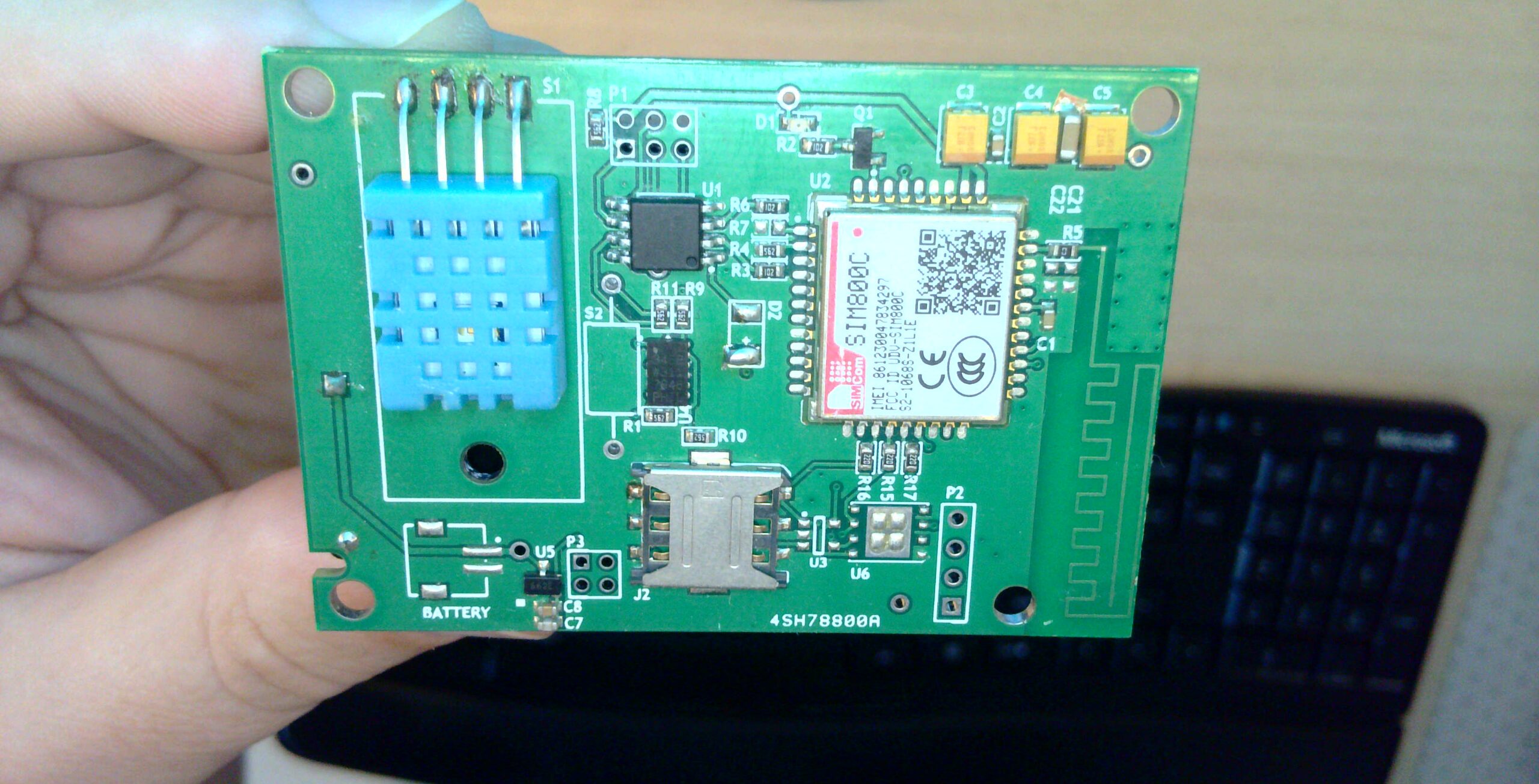
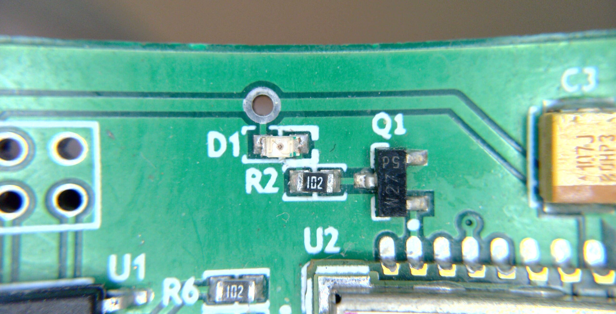
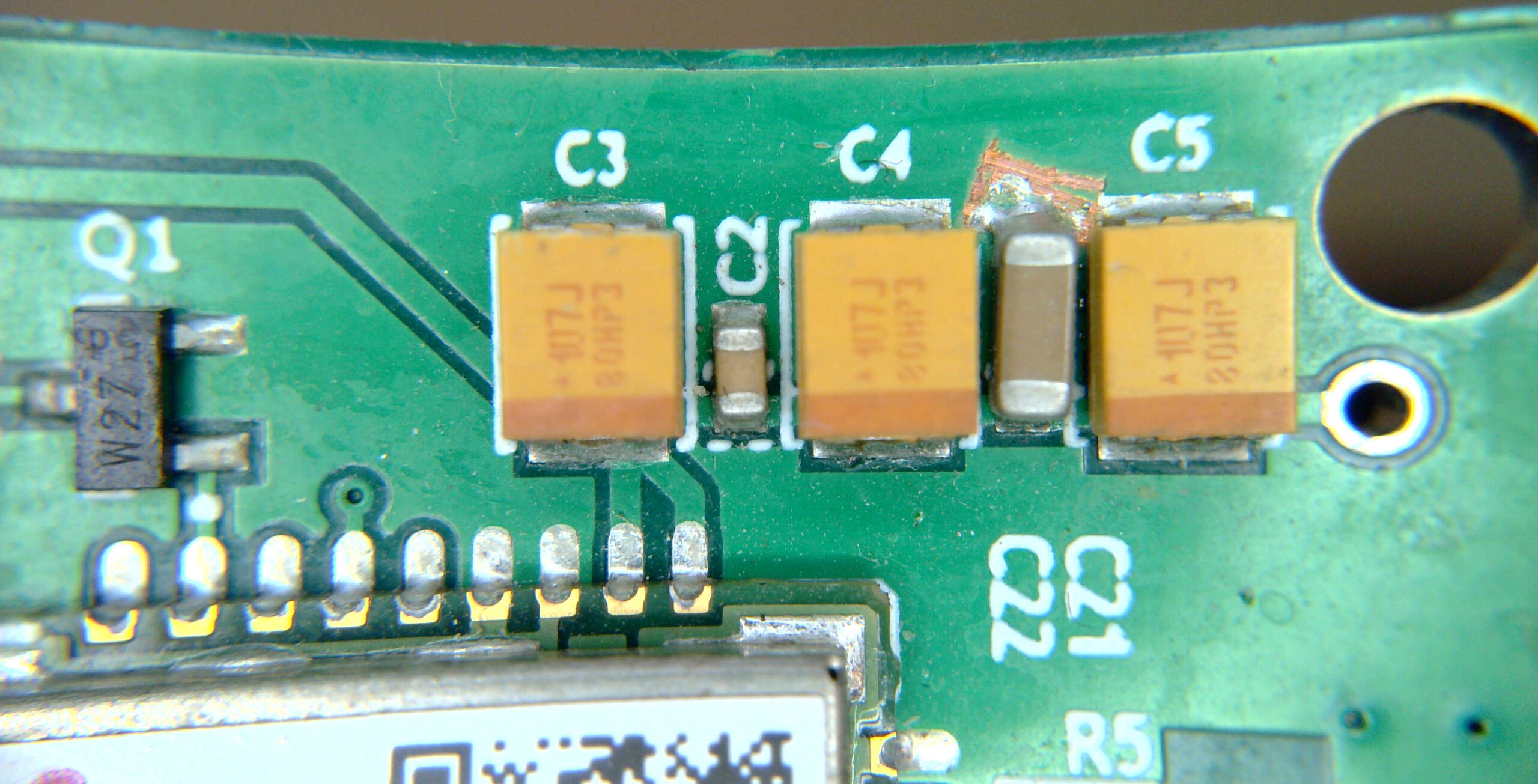
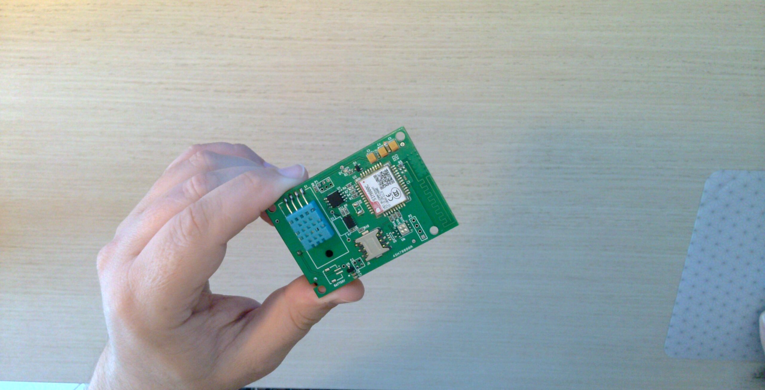
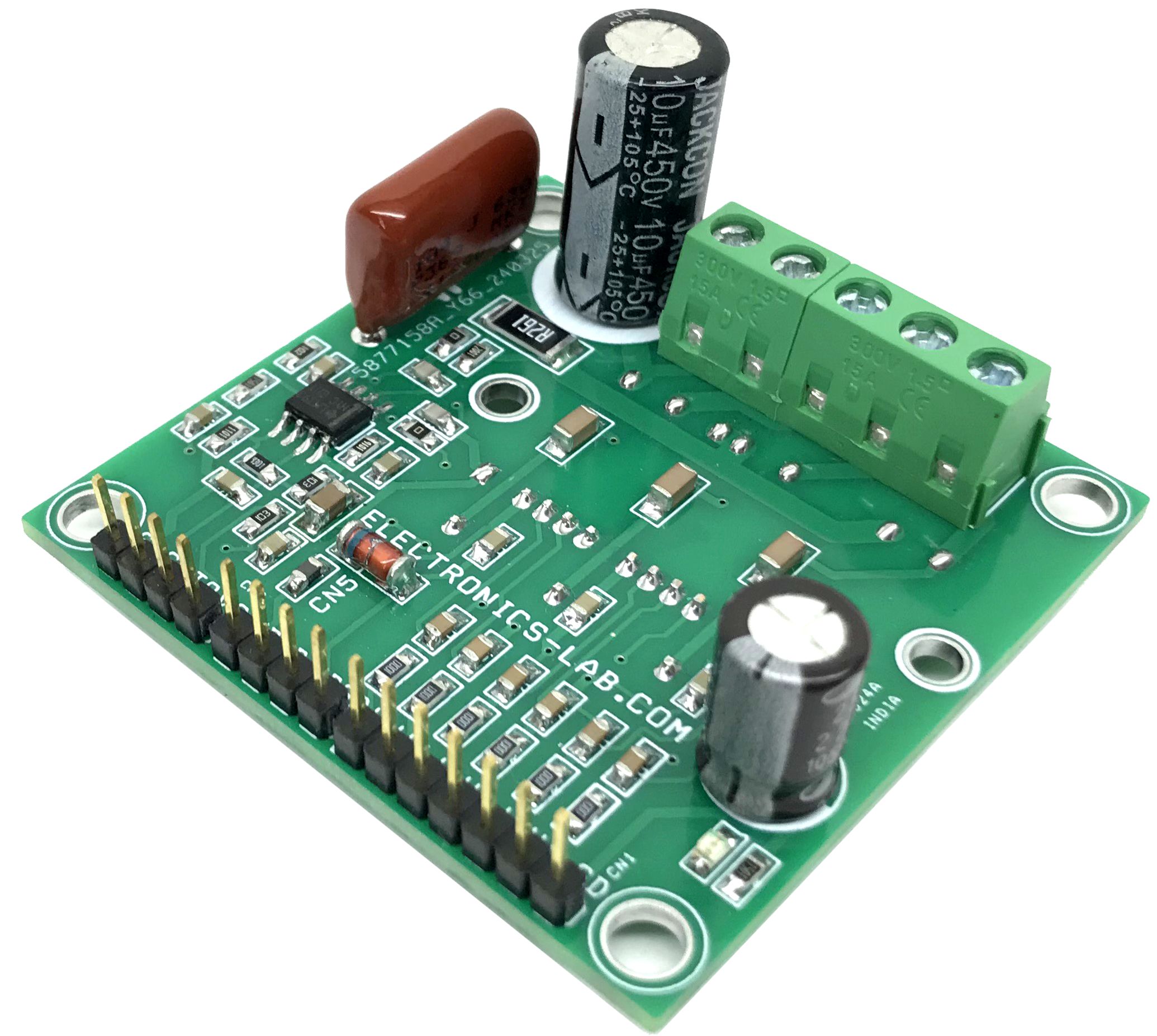
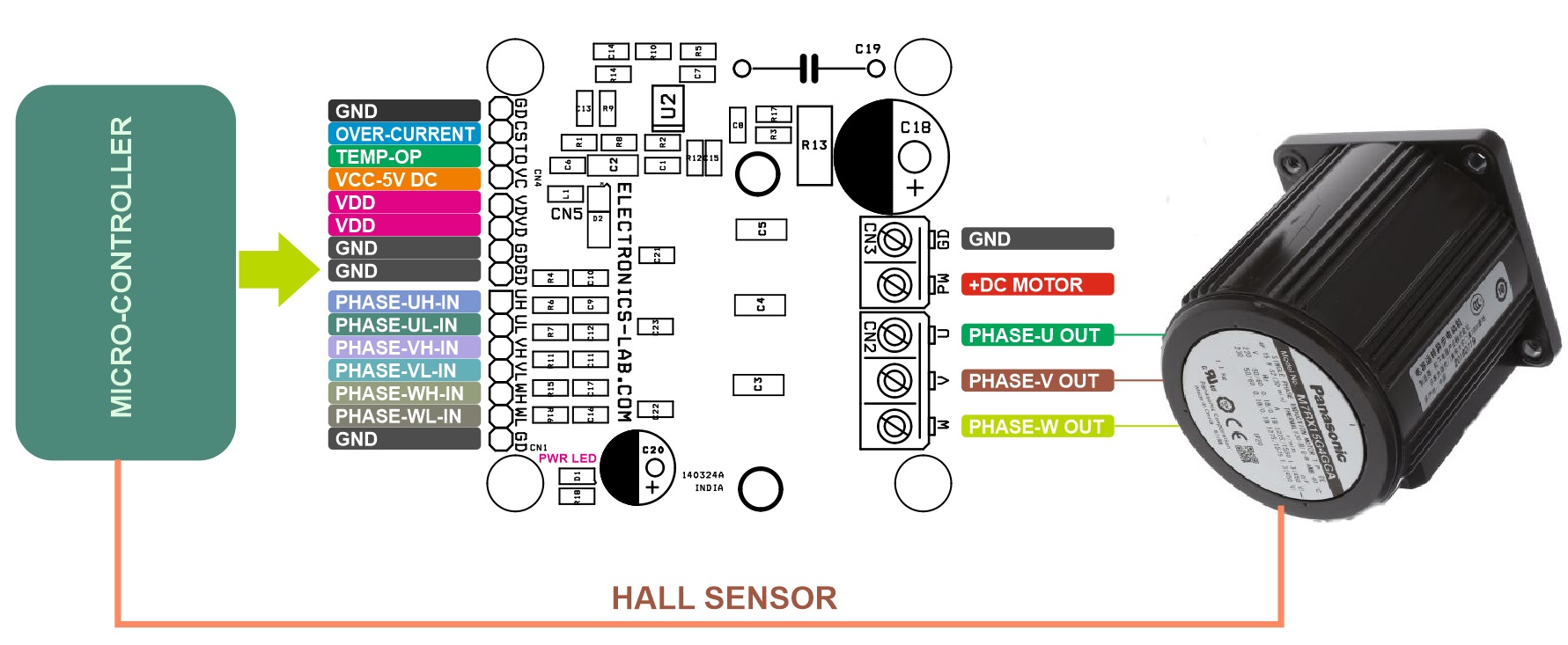
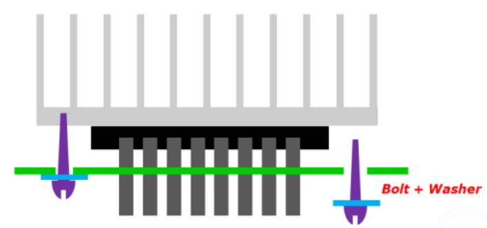
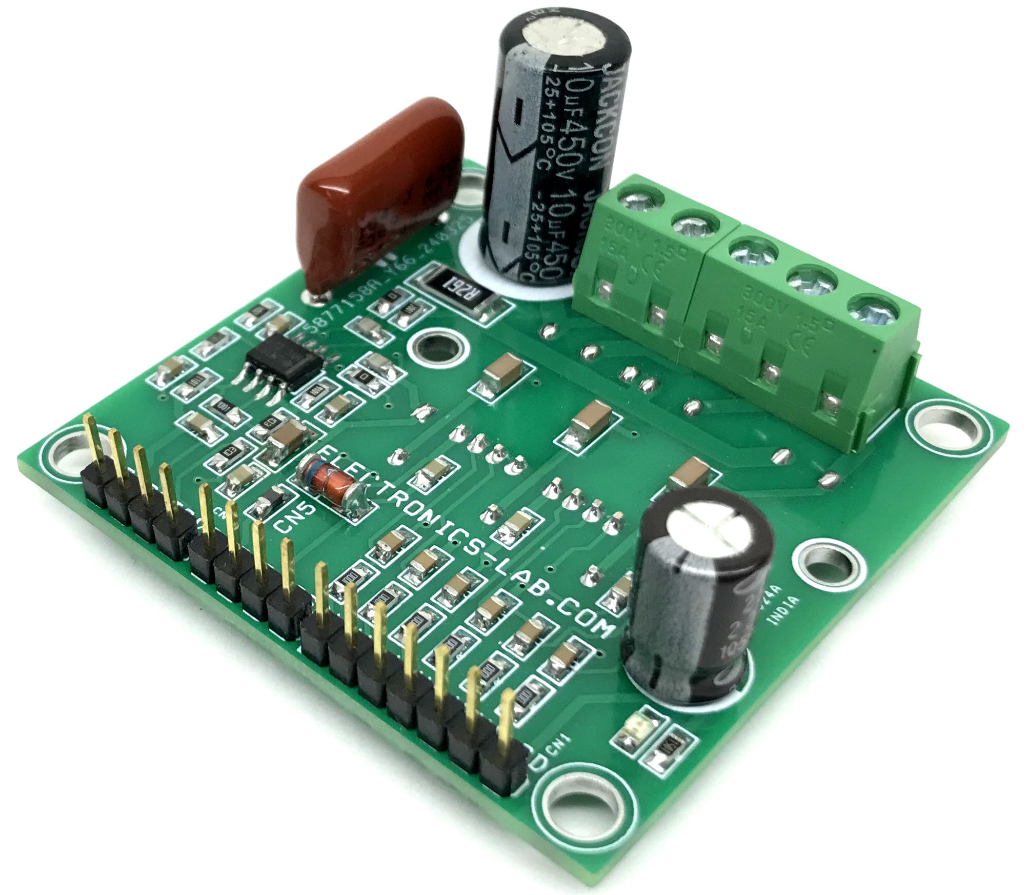
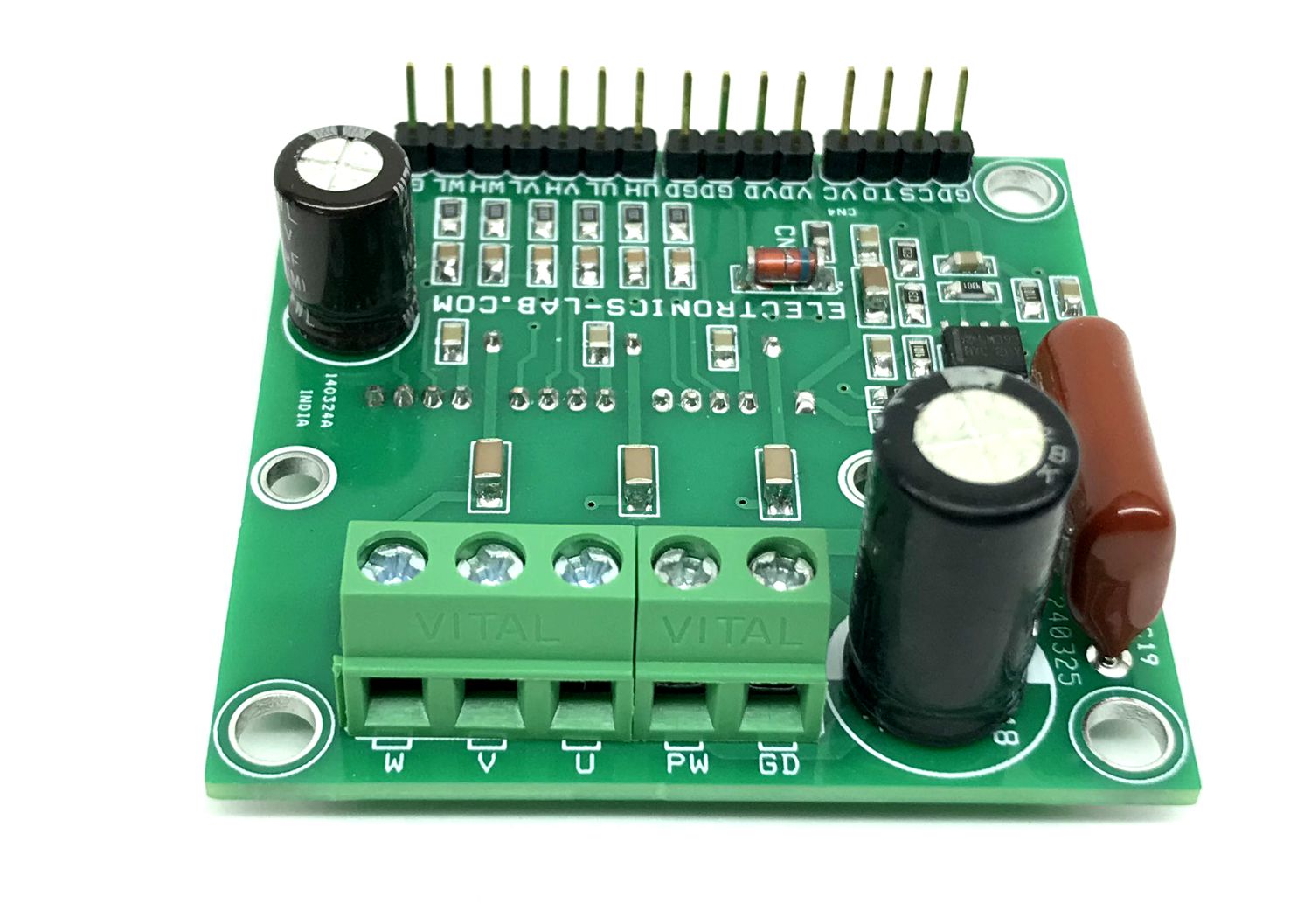
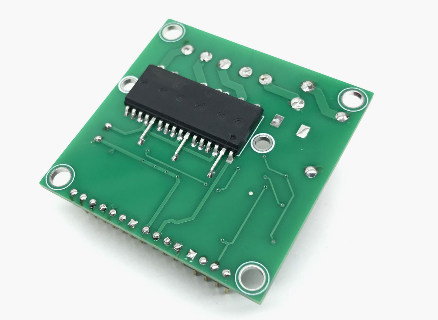
This is a 3-Phase Inverter Driver project designed for Small Power AC Motors. The project is built using FSB50550AT IPM chip. This compact and reliable inverter project is ideal for small power motors such as fans and pumps. An H-bridge configuration can also be created for low current high-voltage brushed DC motors. The Inverter board supports a load up to 2A. The DC power supply voltage is up to 400V DC. The project operates with 6 x PWM signals. Parameters for bootstrap circuit elements are dependent on the PWM algorithm. For 15 kHz switching frequency, Bootstrap capacitors C3, C4, and C5 value is 1uF. Resistor R4, R6, R7, R11, R15, R16 and capacitor C9, C10, C11, C12, C16, C17 prevent improper signal due to surge-noise. The logic supply is protected with a 20V Zener diode, which prevents surges under severe conditions. Comparator U2A provides low output when an overcurrent condition occurs, it measures the current across shunt resistor R13, and normal output is high. Comparator U2B is provided for over-temperature detection, the output of U2B is high when IPM temperature is below 80 degrees C, and goes low when the temperature reaches the threshold. A heatsink is a must for full load current, thus 2 mounting holes are provided throughout the PCB to mount the heatsink as shown in the Figure below. Silicone thermal compound, also called thermal grease, should be applied between the heat sink and the flat surface of the IPM to fill microscopic air gaps due to imperfect flatness that ultimately reduces the contact thermal resistance. The IPM module should be soldered first. Please take care of excessive torque that may bend the PCB.
Note: The project operates with lethal voltage, user must take care of safety and all necessary precautions before testing the project.
Features
Load Power Supply Up to 400V DC
Load Current Continues 2A
Logic Supply 15V DC, Current 100mA Minimum
Power Supply for Over Current/Temperature Circuit (Comparator U2) 5V DC
One Board Power LED for Logic Supply
Shunt and Comparator Based Over Current Output
Over temperature threshold is 80 degrees centigrade.
HVIC for gate driving and under-voltage protection
Active-High interface, can work with 3.3V/5V logic (PWM Signals)
On Threshold Voltage 2.9V, Off Threshold Voltage 0.8V
Optimized for low electromagnetic interference
Isolation voltage rating of 1500Vrms for 1min
PCB Dimensions 53.34 x 52.55 mm
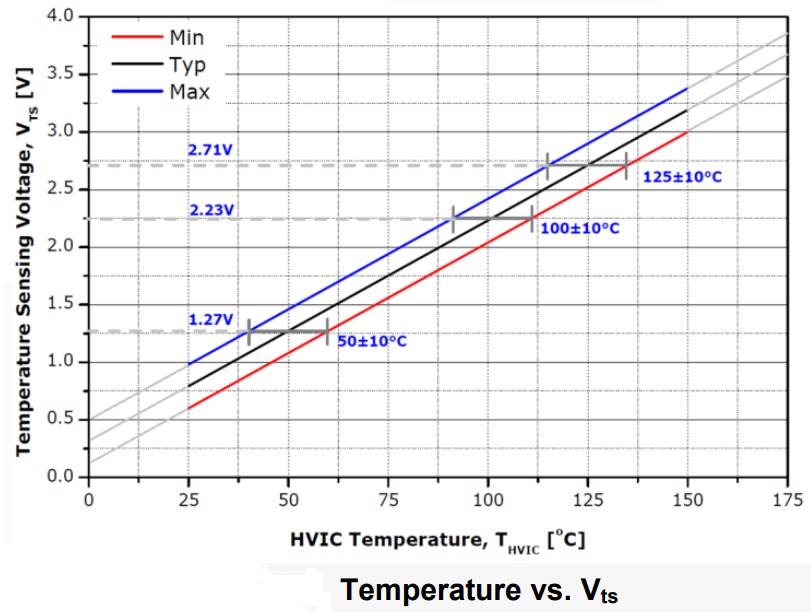
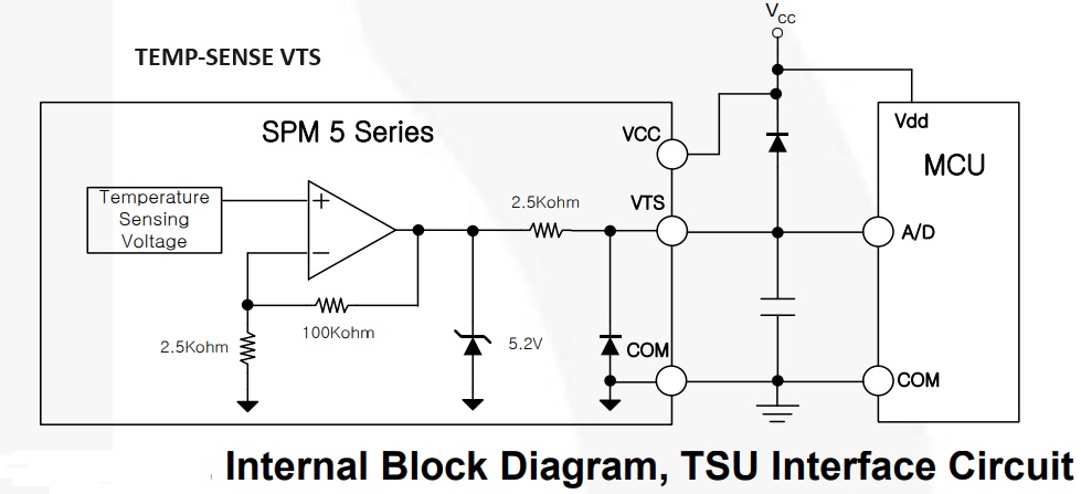
Temperature Sensing Output (VTS) – CN4 Pin 2-TO
Pin: VTS This indicates the temperature of the V-phase HVIC with an analog voltage output. HVIC itself creates some power loss, but mainly heat generated from the MOSFETs increases the temperature of the HVIC. Comparator U2B is used for over-temperature detection. Output is high in normal conditions when the temperature is below 80 degrees, and goes low when over-temperature condition occurs. The over-temperature threshold is 80oC.
These pins are activated by voltage input signals. The terminals are internally connected to the Schmitt trigger circuit.
The signal logic of these pins is active HIGH; the MOSFET turns ON when sufficient logic voltage is applied to the associated input pin.
The wiring of each input needs to be short to protect the module against noise influences.
An RC filter is used to mitigate signal oscillations or any noise that traces of input signals may pick up.
Operation Table Input Signals
HIN 0, LIN 0 = Output Z Both MOSFET Off
HIN 0, LIN 1 = Output 0 Low Side MOSFET On
HIN 1, LIN 0 = Output VDC High Side MOSFET On
HIN 1, LIN 1 = Forbidden Shoot Through
Minimum Pulse Width (Signal Input)
There are input noise filters of 90 ns time constant inside the HVIC. It screens out pulses narrower than the filter time constant. Additional propagation delay in level-shifters and other circuits, together with gate charging time, prevent SPM 5 products from responding to an input pulse narrower than ~120 ns. Gate signal inputs are active-HIGH with 500 kΩ internal pull-down resistors.
FSB50550AT is an advanced power module for motion control, based on fast-recovery MOSFET (FRFET®) technology as a compact inverter solution for small power motor drive applications such as fans and pumps. FSB50550AT contains six FRFET MOSFETs, three half-bridge gate driver HVICs with temperature sensing, and three bootstrap diodes in a compact package fully isolated and optimized for thermal performance. FSB50550AT features low electromagnetic interference (EMI) characteristics by optimizing switching speed and reducing parasitic inductance. Since FSB50550AT employs MOSFETs as power switches, it provides much more ruggedness and larger safe operating area (SOA) than IGBT-based power modules. FSB50550AT is the right solution for compact and reliable inverter designs where the assembly space is constrained.