The project presented here is a low-cost position control closed-loop analog-servo using brushed DC motor and potentiometer as feedback. This project provides all necessary active functions for a closed-loop servo system using a Brushed DC Motor and potentiometer mounted on the output shaft of the DC Motor with Gear. The project is ideally suited for almost any servo positioning application. Can be used in applications such as side mirror movement control for cars, car head lamp beam control, animatronics, robotics, etc.
The project requires a special mechanism, where the DC motor’s output shaft is mechanically couple with the potentiometer shaft using a reduction gear. Approx. reduction ratio 15-50: 1. When the reference pot is turned, the motor shaft will follow the potion. This will provide a maximum rotation of 270 degrees. Multi rotation is possible with the help of a multiturn potentiometer.
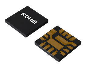
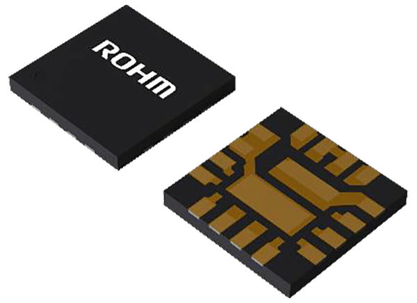
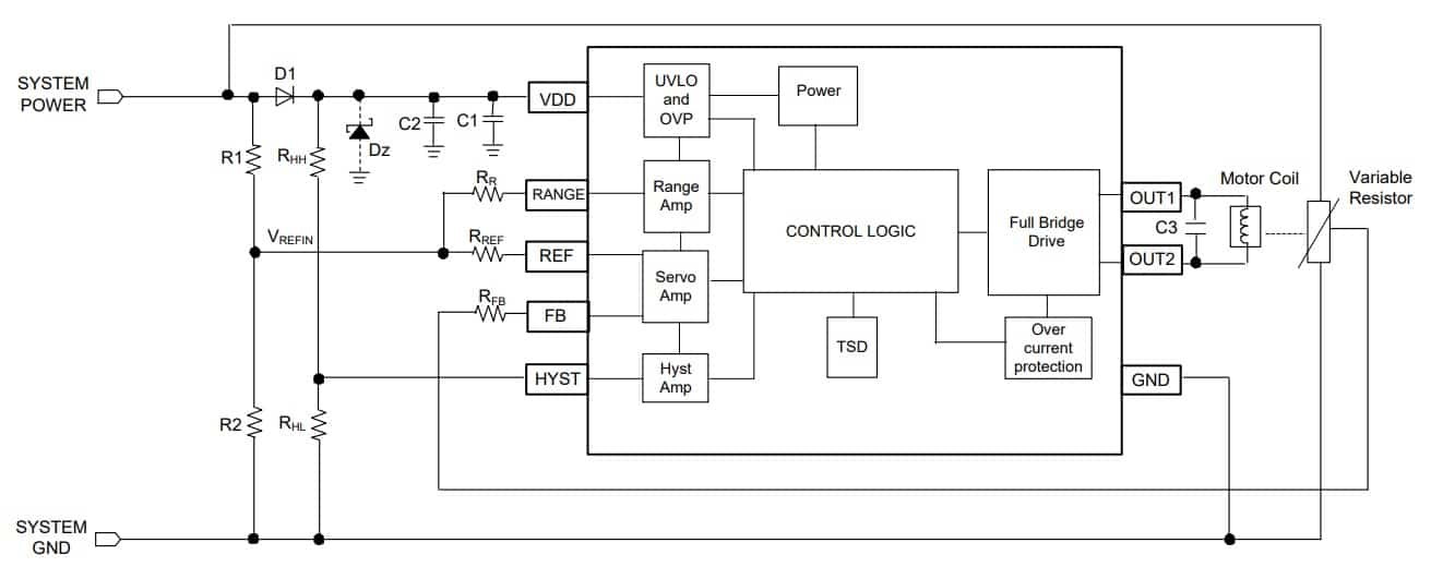
The project is based on the ZXBM5409Q chip from Diode Incorporation which is a protected H-bridge driver designed specifically for manual automotive headlight-beam control and industrial servo control applications with DC-brush motor loads. The integrated full-bridge driver output stage is composed of high-current, low-RDSON H-bridge MOSFETs to maximize efficiency. To simplify the circuit design and minimize external components, the device integrates voltage and temperature-compensated internal references, amplifiers, and output H-bridge power switches with low RDSON. For system flexibility, the servo controls forward and reverse hysteresis, dead band, and angle amplification are easily programmable by external resistors. To help protect the motor coil, the ZXBM5409Q provides fault condition protection, such as RANGE input short to GND, short-to supply voltage, or broken wires, by stopping the motor and disconnecting the output stage. In case of supply undervoltage and overvoltage, the device shuts down the output drive to help prevent overvoltage stress on the coil. The overcurrent protection monitors the output current and shuts down the outputs stage with periodic retry to help protect the coil from device burnout. Overtemperature shutdown provides thermal protection for the device.
Features
- Wide Operating Voltage Range: 8V to 18V
- Output Current 800mA (Peak 1.6A)
- Fault Protection – RANGE Short to GND, Supply, or Broken Wires
- Overvoltage and Undervoltage Shutdown
- Overcurrent Protection
- Thermal Protection
- PCB dimensions: 36.04 x 26.51 mm
Thermal Shutdown Protection
The device has an internal thermal shutdown to prevent a thermal runaway scenario. The thermal shutdown is triggered when the junction temperature of the device reaches +170°C. It will remain in standby mode until the junction temperature falls by +30°C.
Overcurrent Protection
The internal overcurrent protection (OCP) threshold is 1.6A typical at 12V supply +25°C. When the motor current exceeds the OCP threshold for longer than 2µs typical on any of the H-bridge switches, the device switches off all the output switches and remains off for 5ms typical. The IC returns to normal operation after the 200µs if overcurrent condition goes away. If the motor current is still higher than the OCP threshold, the device enters another 5ms standby mode.
Overvoltage Shutdown of Output Drive
When the supply voltage exceeds the overvoltage shutdown threshold, VOV_TH, the ZXBM5409Q shuts down all the output drive switches and enters standby mode to help prevent overvoltage stress on the coil. The driver returns to normal condition if the supply voltage drops below
VOV_RLTH—provided no other fault condition or signals are preventing it from entering normal operation
Undervoltage Lockout
To make sure the minimum voltage required to operate the driver is supplied, the ZXBM5409Q has an undervoltage lockout. At start up the device only starts if the supply voltage is typically over VUVLO_RLTH. During normal operation, the device switches off all the output switches and powers down if the supply voltage drops below VUVLO_TH typical. When the supply voltage drops below undervoltage lockout threshold, VUVLO_TH_R, the ZXBM5409Q shuts down all the output drive switches and enters standby mode to help prevent overvoltage stress on the coil.
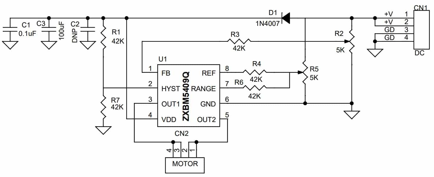
Schematic
Parts List
| NO | QNTY | REF | DESC | MANUFACTURER | SUPPLIER | SUPPLIER PART NO |
|---|---|---|---|---|---|---|
| 1 | 1 | CN1 | 4 PIN MALE HEADER PITCH 2.54MM | WURTH | 732-5317-ND | |
| 2 | 1 | CN2 | 4 PIN MALE HEADER PITCH 2.54MM | WURTH | 732-5317-ND | |
| 3 | 1 | C1 | 0.1uF/50V SMD SIZE 0805 | MURATA/YAGEO | ||
| 4 | 1 | C2 | DNP | |||
| 5 | 1 | C3 | 100uF/25V ELECTROLYTIC | RUBYCON | DIGIKEY | 1189-4162-3-ND |
| 6 | 1 | D1 | 1N4007 SMD | SMC DIODE | DIGIKEY | 1655-1N4007FLCT-ND |
| 7 | 5 | R1,R3,R4,R6,R7 | 42K 1% SMD SIZE 0805 | MURATA/YAGEO | DIGIKEY | |
| 8 | 2 | R2,R5 | 5K POTENTIOMETER | BOURNS | DIGIKEY | PDB181-P415K-103B-ND |
| 9 | 1 | U1 | ZXBM5409Q | DIODE INC. | DIGIKEY | ZXBM5409Q-N-UDI-ND |
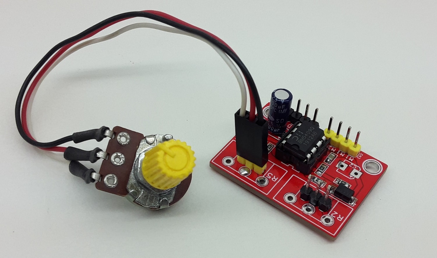
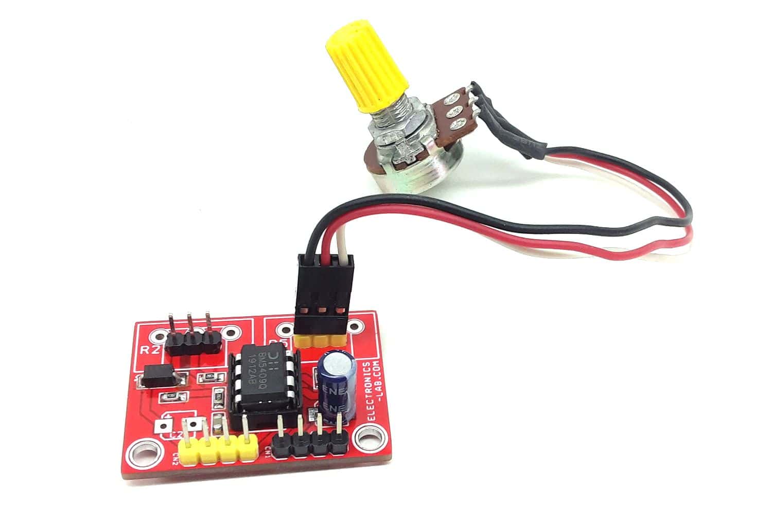
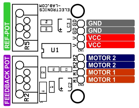
Connections 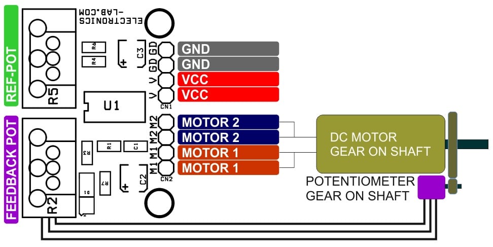
Block Diagram
Gerber View
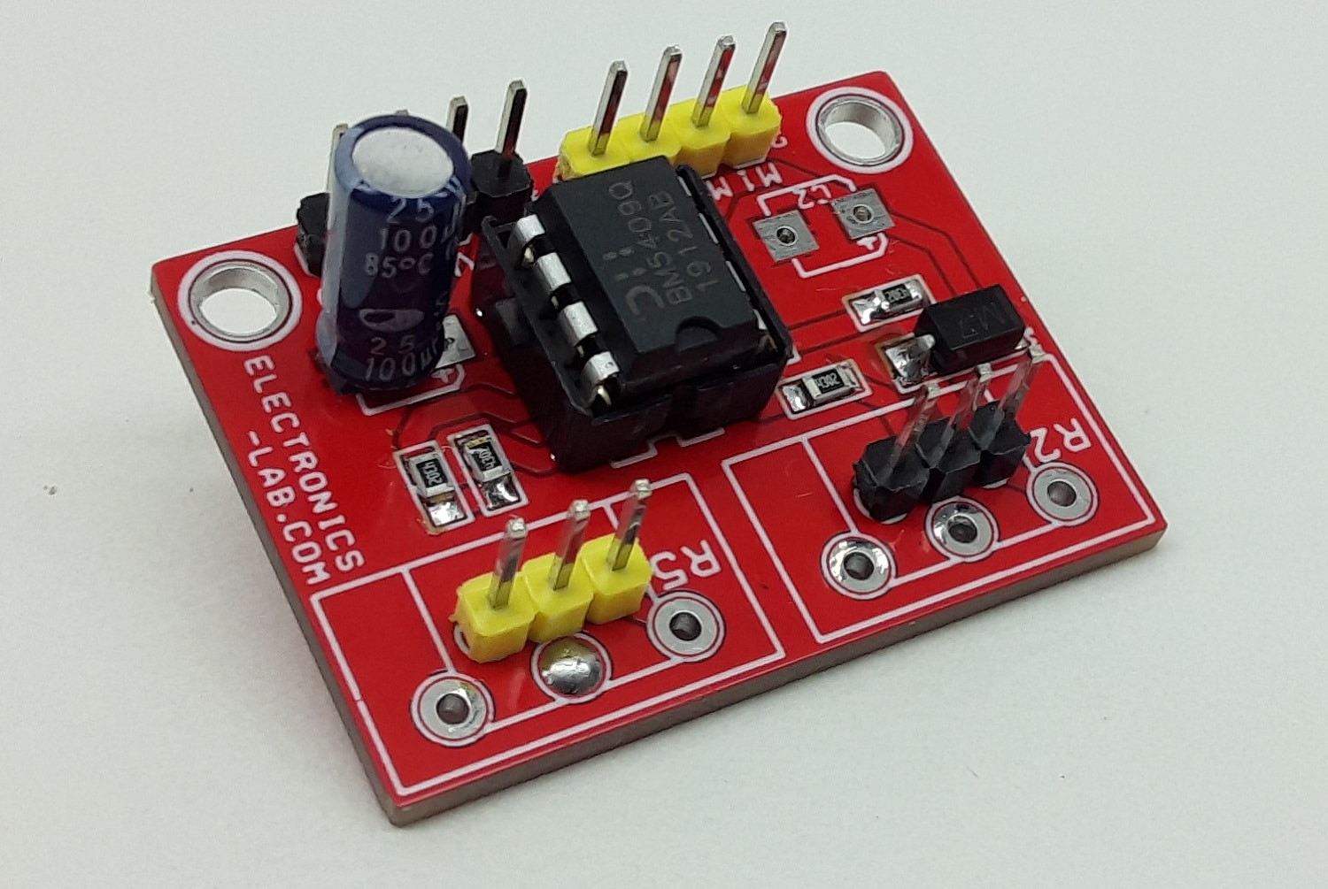
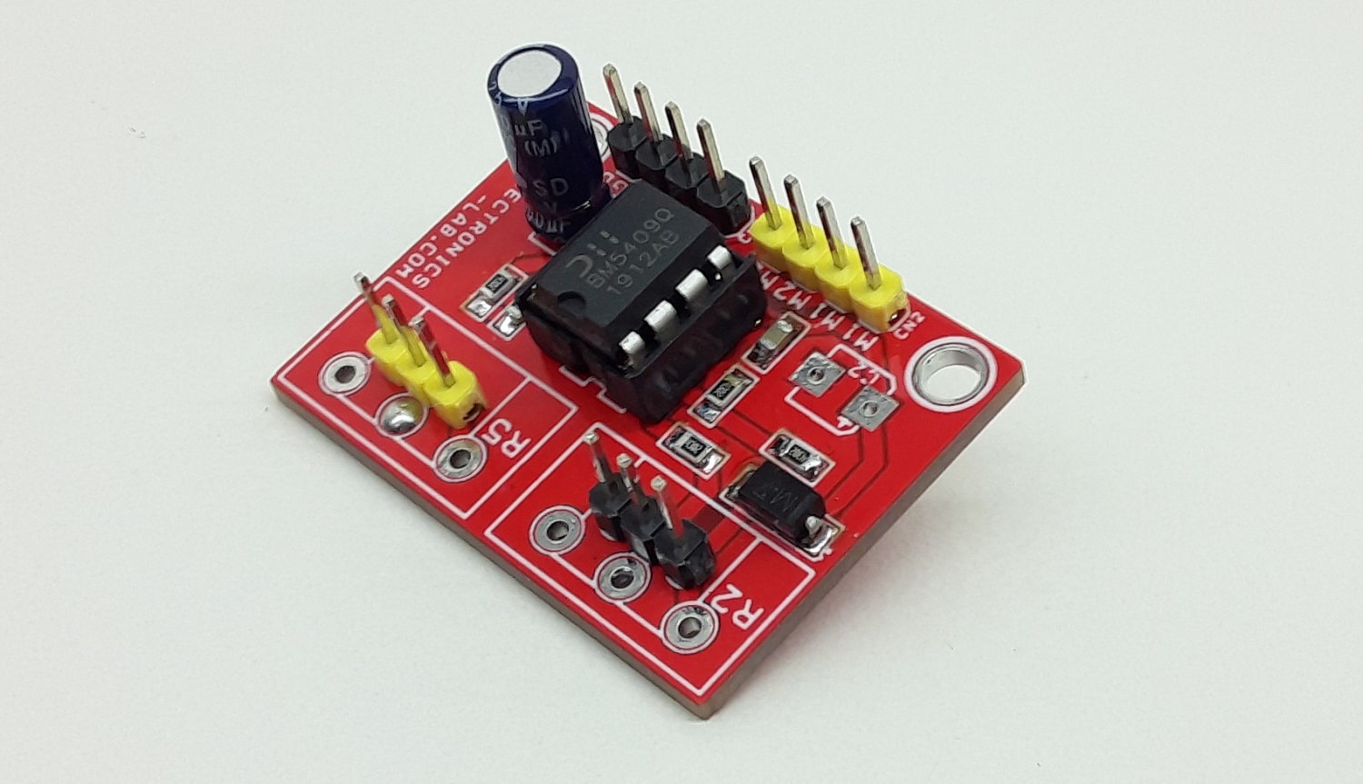
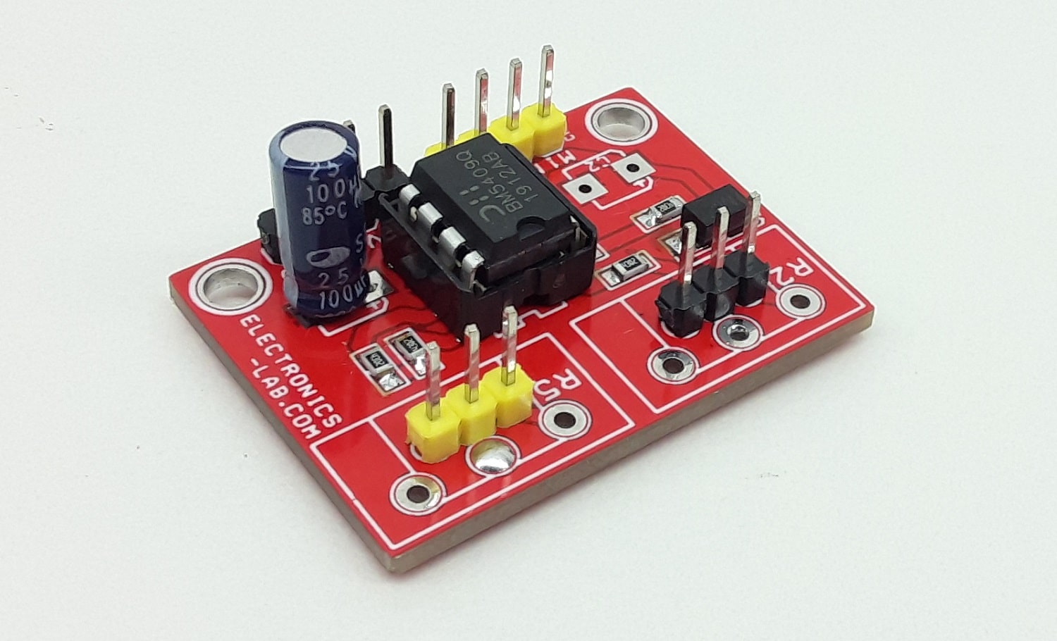
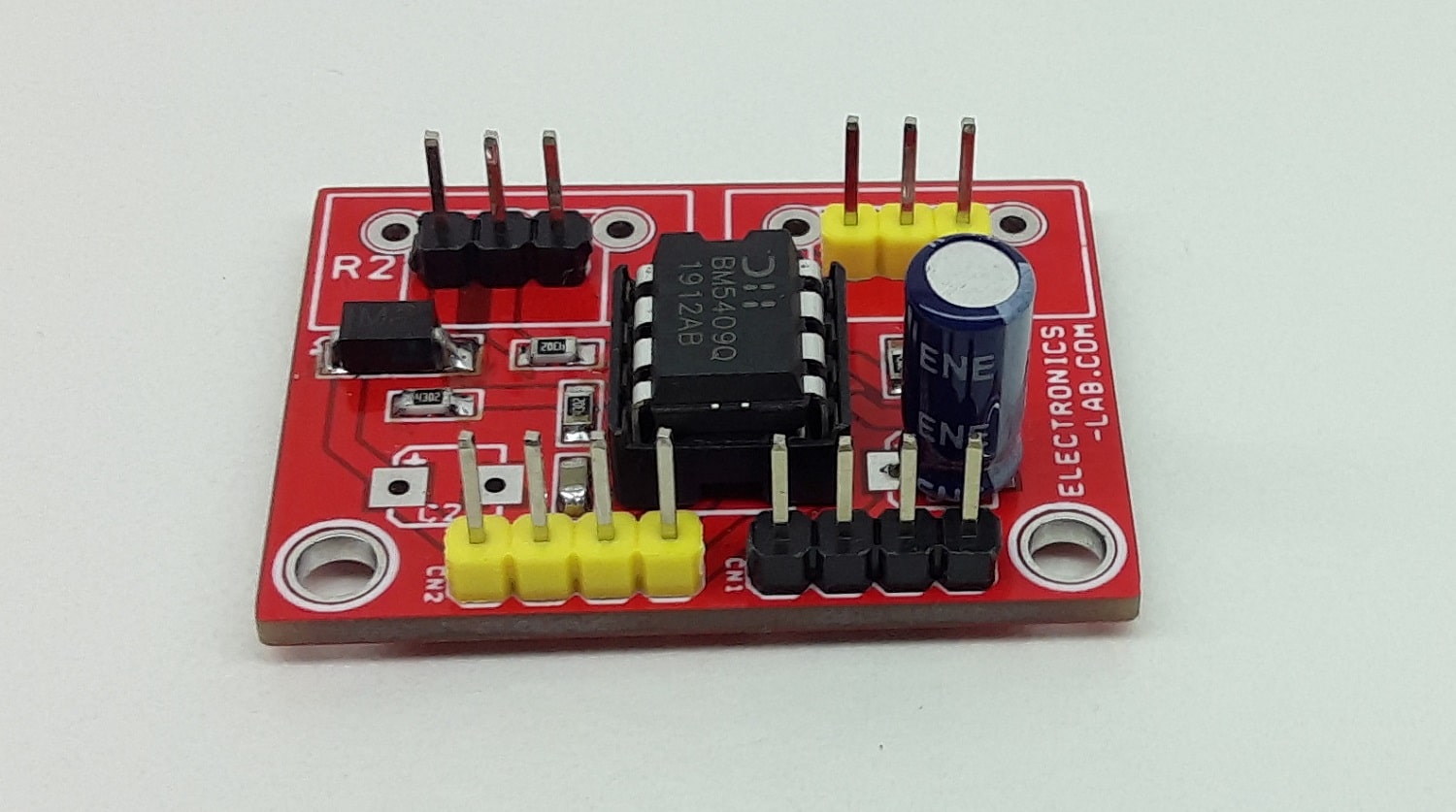
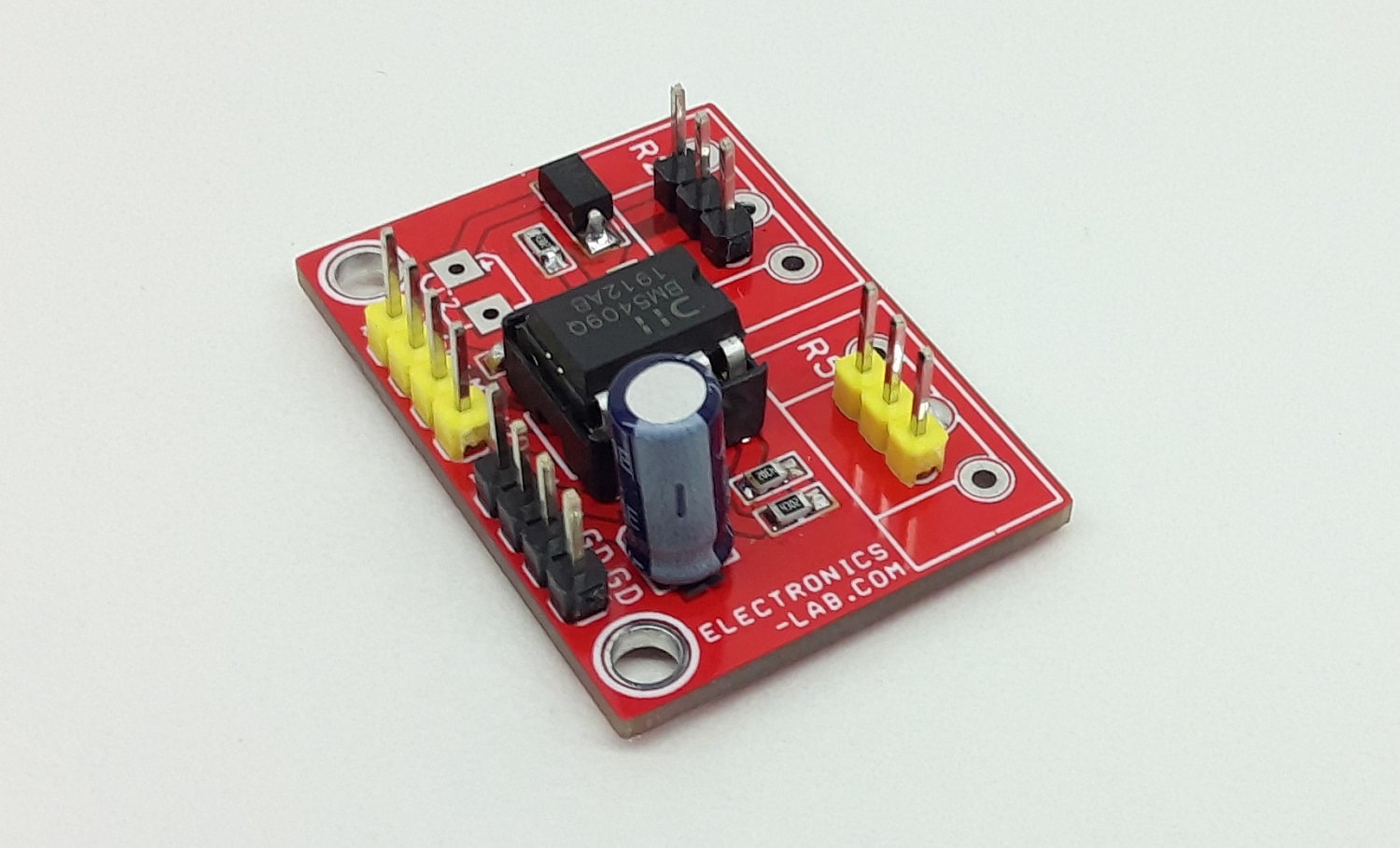
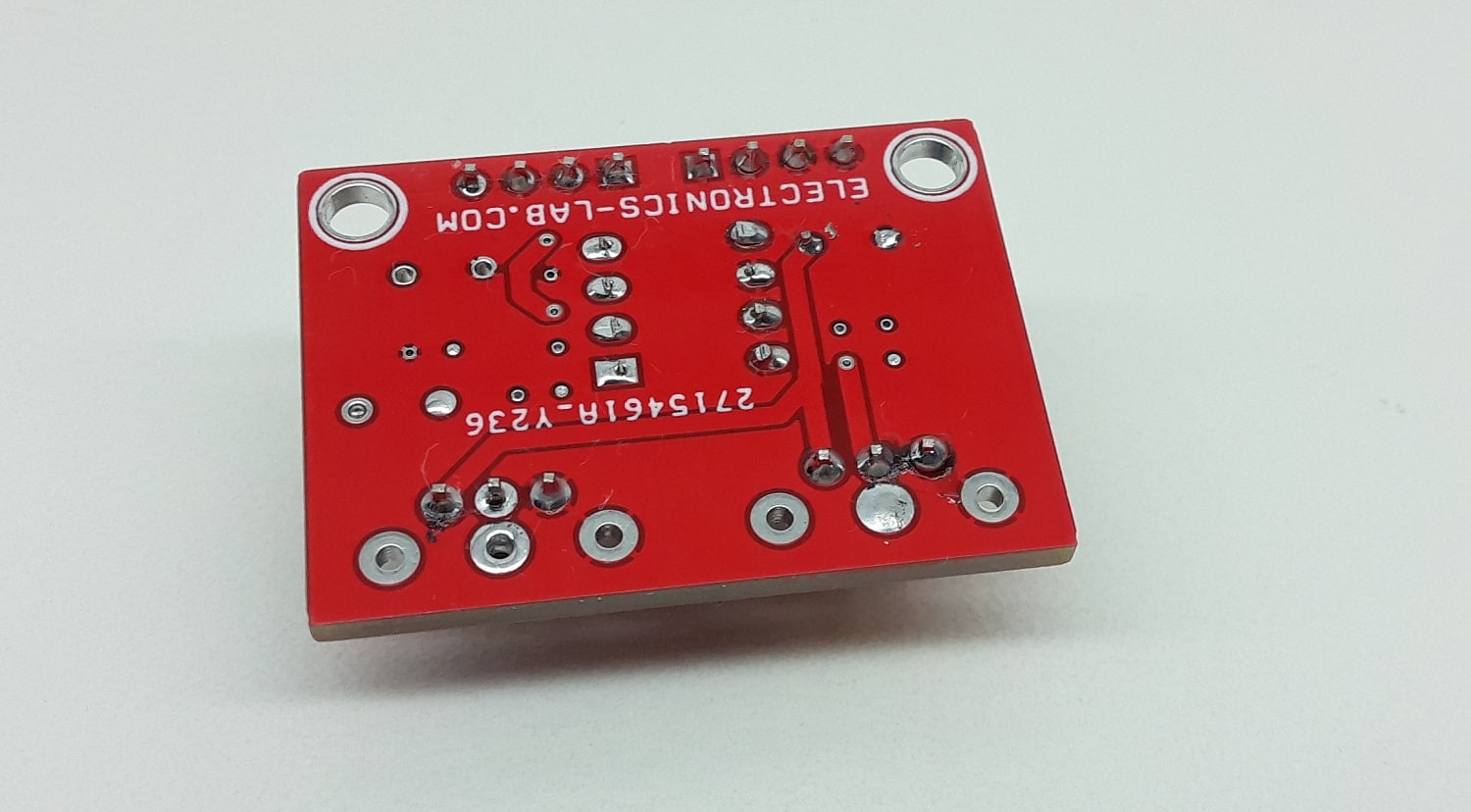
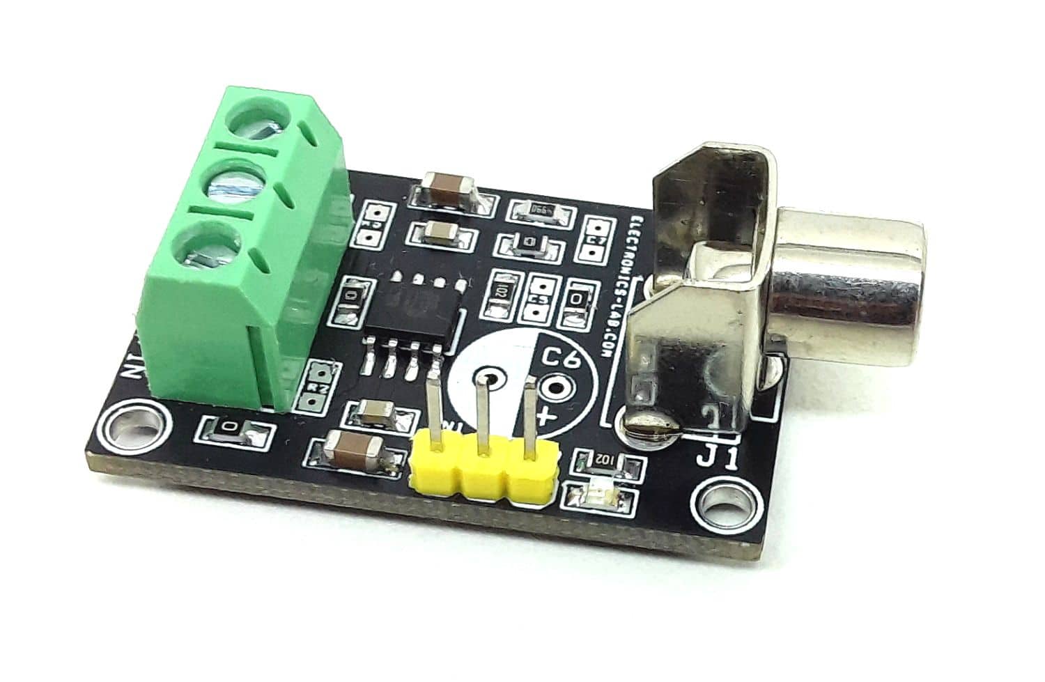
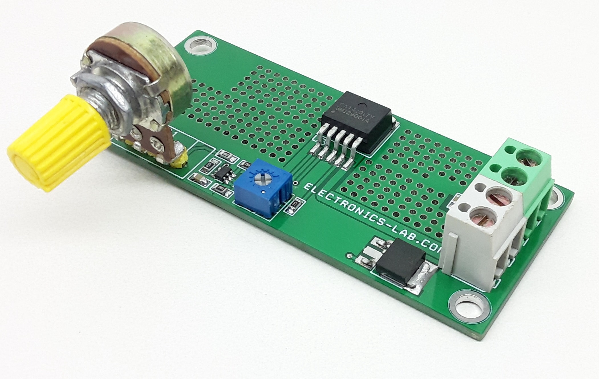
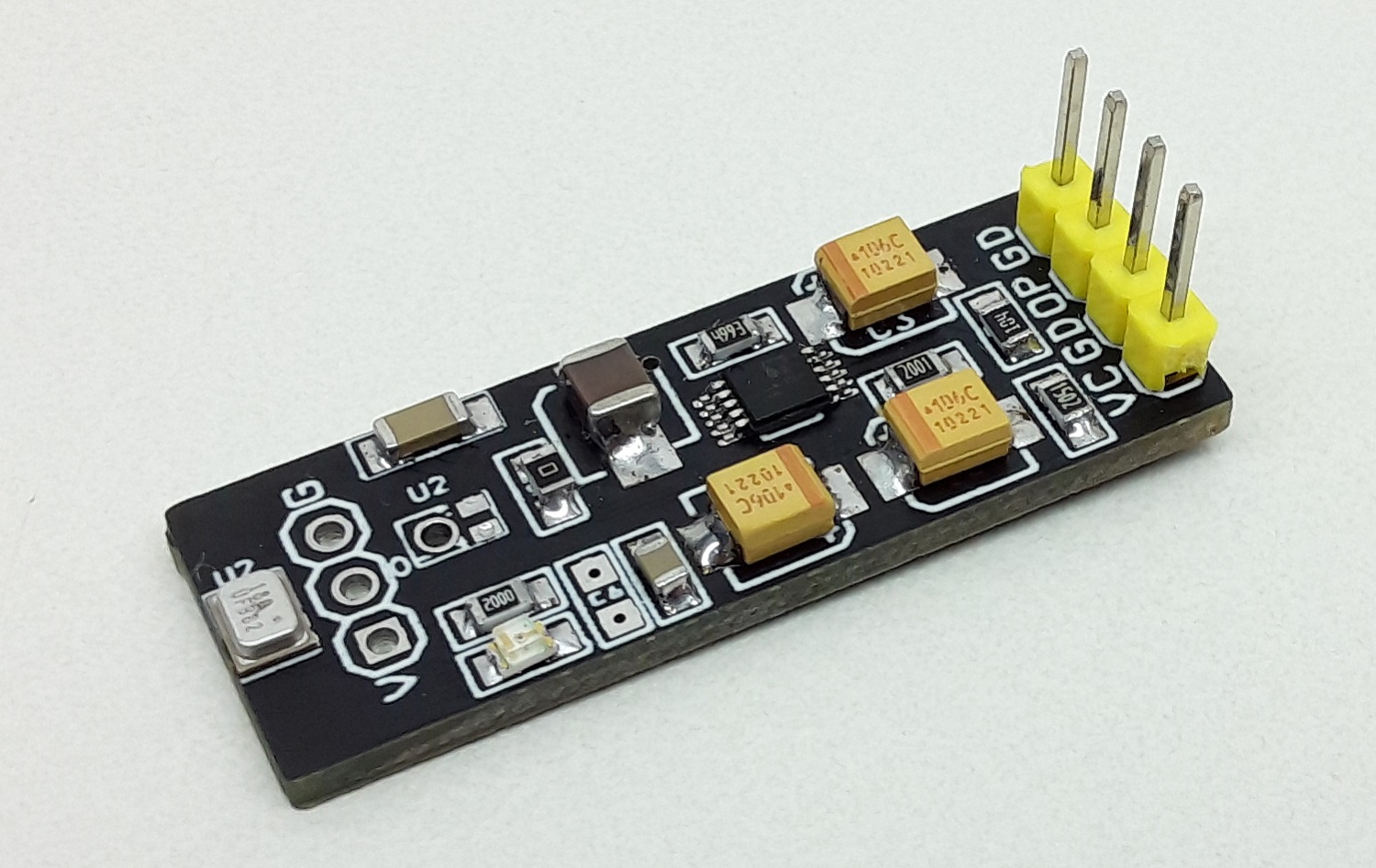
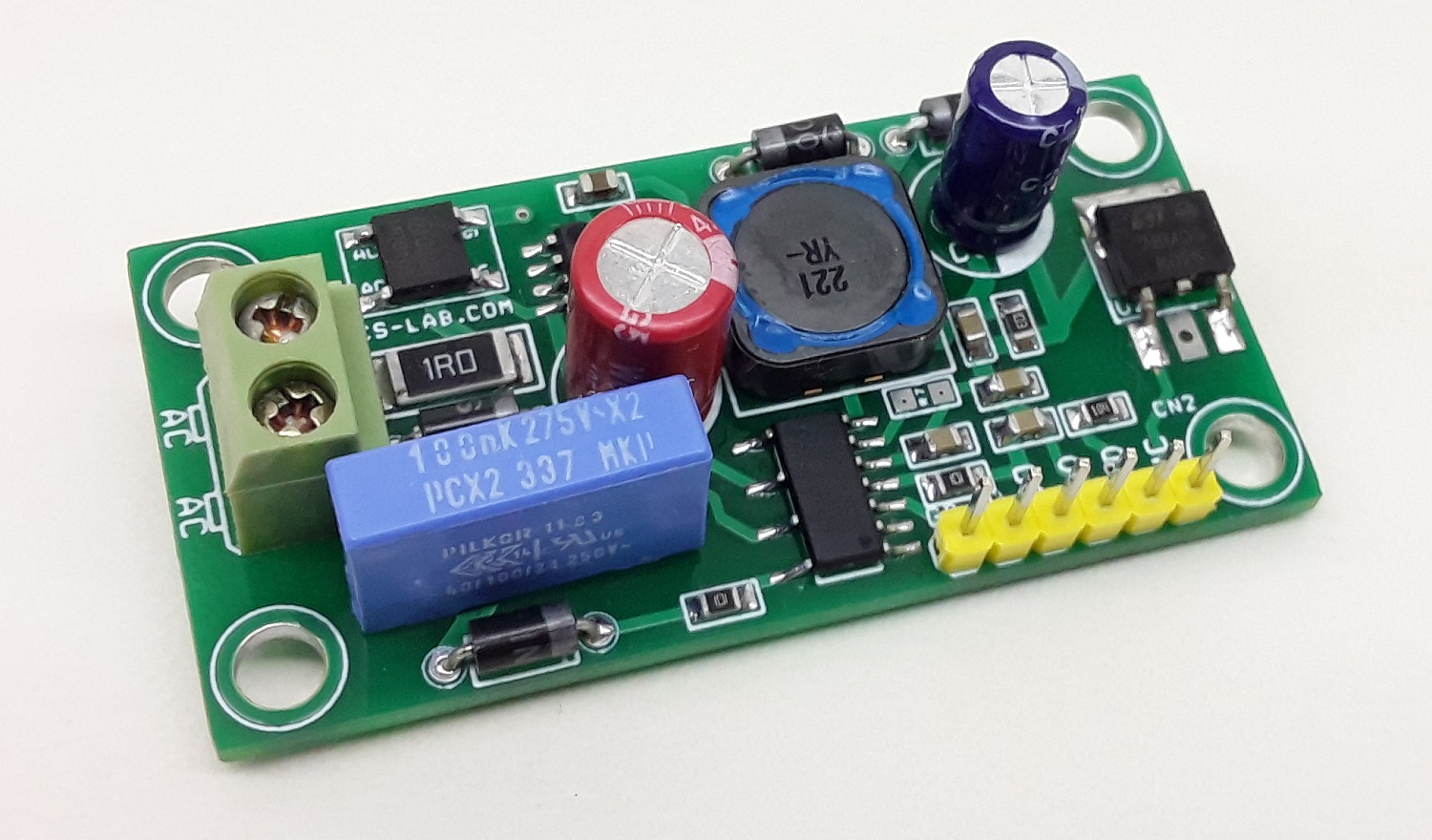
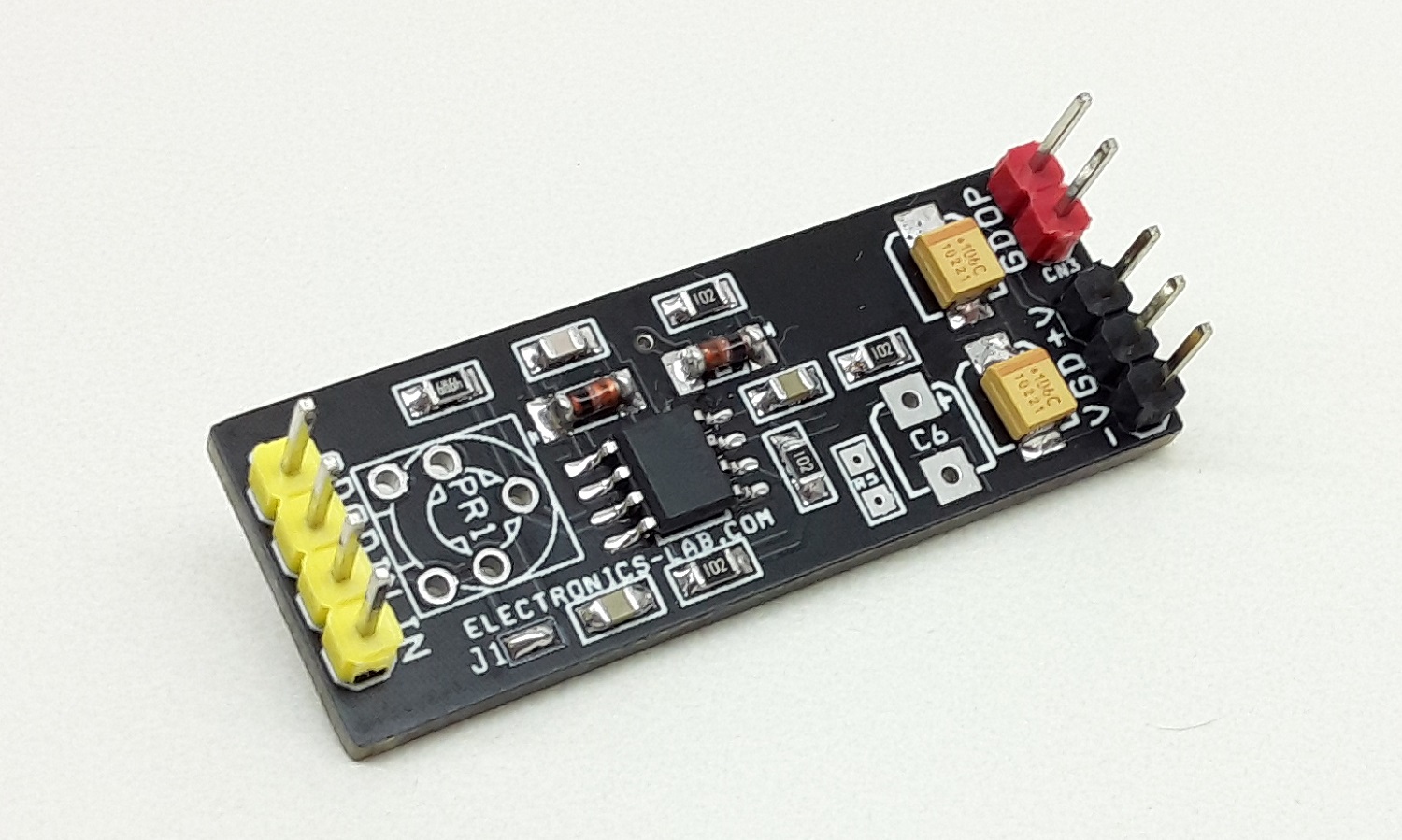
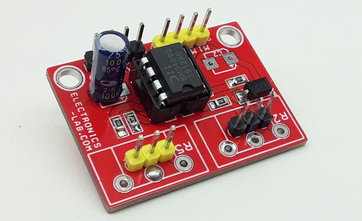
Photo