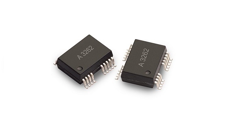
The ACFJ-3262 is a 10 A dual-channel gate drive optocoupler device in the SO-24 package designed for high voltage, space-constrained industrial applications
The ACFJ-3262 is a 10 A dual-channel gate drive optocoupler device in the SO-24 package designed for high voltage, space-constrained industrial applications like motor drives and inverters. The new package features a 600 V CTI mold which reduces the creepage requirement due to high insulation voltage in a compact footprint. It features transient immunity (CMTI) greater than 100 kV/μs, preventing erroneous gate driver failures in noisy environments. The new device has less than 95 ns propagation delay, enabling high frequency switching to improve MOSFET and GaN transistor/FET driving efficiency
Key features
- 10 A max peak output current
- Dual-channel with 2.8 mm creepage between channels
- 600 V CTI mold
- Dual rail-to-rail outputs for separate source and sink
Additional features
- Industry’s first 10 A gate drive optocouplers
- 95 ns max propagation delay
- 100 kV/µs minimum common mode rejection (CMR) at VCM = 1000 V
- ICC = 4.0 mA max supply current
- Wide operating VCC range: 10 to 25 V
- 600 V CTI SO-24 package
- Industrial temperature range:
- From -40 to +125 °C
- Safety approvals:
- UL recognized: 5000 VRMS for 1 minute.
- CSA approved
- IEC/EN/DIN EN 60747-5-5 VIORM = 1.230 VPEAK
Applications
- MOSFET and GaN transistor/FET gate drive
- AC and brushless DC motor drives
- Renewable energy inverters and storage
- Industrial inverters
- Switching Power Supplies (SMPS)
more information: https://www.broadcom.com/products/optocouplers/industrial-plastic/isolated-gate-drive-optocouplers/gate-drives/acfj-3262-000e