![]()
Maxim Integrated MAX25256 H-Bridge Transformer Driver provides a simple solution for making isolated power supplies up to 10W. The device drives a transformer’s primary coil with up to 300mA of current from a wide 8V to 36V direct current (DC) supply. The transformer’s secondary-to-primary winding ratio defines the output voltage, allowing the selection of virtually any isolated output voltage.
The device features adjustable current limiting, allowing indirect limiting of secondary-side load currents. An external resistor sets the current limit of the MAX25256. An output asserts when the device detects an overtemperature or overcurrent condition. In addition, the device features a low-power mode to reduce the overall supply current to 0.65mA (typ) when the driver is not in use.
The device can be operated using the internal oscillator or driven by an external clock to synchronize multiple Maxim MAX25256 devices and precisely set the switching frequency. Internal circuitry guarantees a fixed 50% duty cycle to prevent DC flow through the transformer, regardless of which clock source is used.
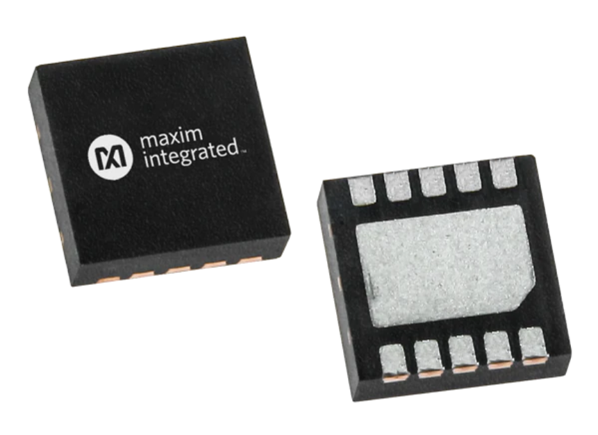
The device is available in a small 10-pin (3mm x 3mm) TDFN package and is specified over the -40°C to +125°C automotive temperature range.
Features
- Simple, flexible design
- 8V to 36V supply range
- Up to 90% efficiency
- Provides up to 10W to the transformer
- Undervoltage Lockout (UVLO)
- 2.5V to 5V compatible logic interface
- Internal or external clock source
- Adjustable overcurrent threshold
- Integrated system protection
- Fault detection and indication
- Overcurrent limiting
- Overtemperature protection
- Saves space on board
- Small 10-pin TDFN package (3mm x 3mm)
- AECQ-100 qualified
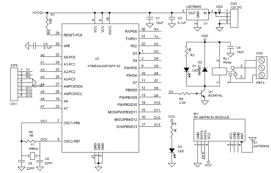
Block Diagram
![]()
more information: https://datasheets.maximintegrated.com/en/ds/MAX25256.pdf