Dual Joystick RF Remote Transmitter with NRF24L01 RF module – 2 Joystick Control

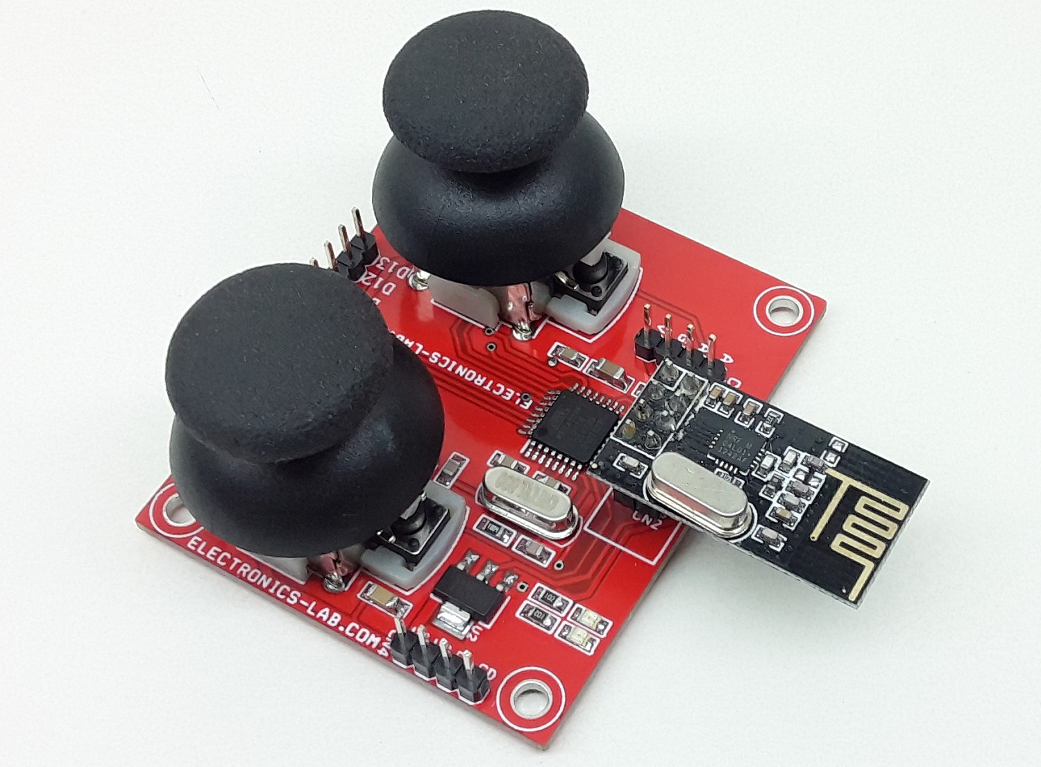
This is an Arduino compatible open-source hardware that includes 2 x Joysticks, NRF24L01 RF module, Atmega328 microcontroller, 3.3V regulator, power LED, function LED, Arduino programming connector, and other required components. This board can be used for the development of various applications such as Gaming, Remote RC servo driver, Robotics, and many more. Connector CN3 was provided to program the ATMEGA328 microcontroller using Arduino IDE.

Dual Joystick RF Remote Transmitter with NRF24L01 RF module – 2 Joystick Control – [Link]

8 Channel RC Servo Driver Over RF Link using NRF24L01 RF Module – Arduino Compatible

This is an easy-to-build open-source Arduino compatible board that enables driving 8 RC servos over NRF24L01 RF Link. The project can be used as a standalone RC servo driver or 8 channel RF remote-controlled RC servo Receiver. An optional OLED display option can be used to develop RC signal monitor. The tiny module contains an ATmega328 microcontroller, connectors for 8 x Servo interface, DC supply connector, bulk electrolytic capacitor C5 on DC supply to provide jitter-free smooth movement of RC servos. Operating Supply 5V DC.

8 Channel RC Servo Driver Over RF Link using NRF24L01 RF Module – Arduino Compatible – [Link]

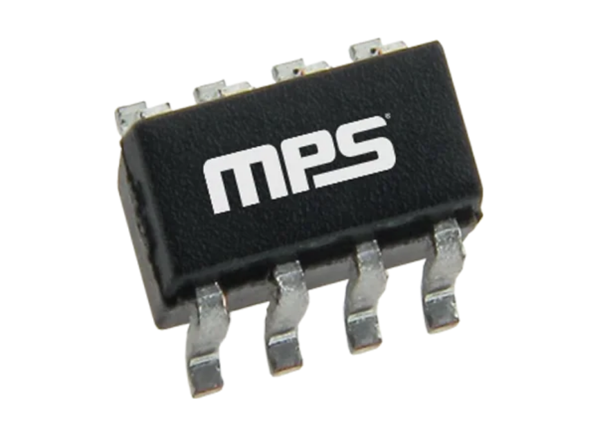
Monolithic Power Systems (MPS) MP3362 Boost LED Driver

Monolithic Power Systems (MPS) MP3362 Boost LED Driver is a fixed-frequency converter for low-current and high-current boost applications. The driver features a low 0.2V feedback voltage for higher efficiency in white LED driver applications. The MP3362 regulates the output voltage up to 36V with an efficiency as high as 95%. Current mode regulation and external compensation components allow the MP3362 control loop to be optimized across a wide variety of input voltages.

Features

  • 3V to 36V input voltage range
  • 4A peak current limit
  • 0.3μA shutdown current
  • Low 200mV feedback voltage
  • Configurable 200kHz to 2.2MHz fSW
  • Internal 80mΩ, 40V power switch
  • High efficiency
  • Analog and PWM dimming
  • Under-voltage lockout protection
  • Open/short LED protection
  • Short FB protection
  • Soft-start operation
  • Thermal shutdown
  • Available in a TSOT23-8 package

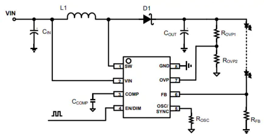
Typical Application

more information: https://www.monolithicpower.com/en/mp3362.html

Ultra-Small Chip Level DC/DC Converter to Meet Isolation Protection Requirements

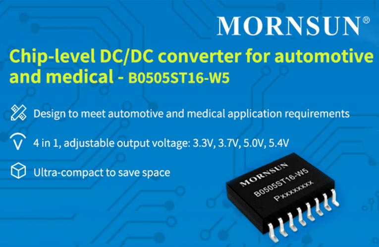
The new chip-level DC/DC converter, B0505ST16-W5 from Mornsun is designed to meet automotive and medical application requirements. This fixed input 0.5W DC/DC converter is the SMD device with reinforced 5KVAC high isolation and trimable output voltages of 3.3V, 3.7V, 5V, 5.4V available in a miniature SOIC16 package, with control ON/OFF pin that has a wide operating temperature of -55c to +125c.

The high-isolation, high-pressure B0505ST16-W5 DC-DC converter meets the isolation protection requirements of 2 MOPP, with an isolation voltage of 5000VAC, a system operating voltage of 849VDC, an isolation capacitor of up to 3.5pF, and is designed to meet IEC/EN 60601 standards. At a high temperature of 125 degrees C, the device can be used with a 55% load and can be widely used in industries with high-temperature requirements, such as automotive electronics.

Key Features of B0505ST16-W5 DC/DC Converter

  • Strengthen insulation and isolate voltage 5000VAC
  • Electrical gap/climbing distance ≥8mm, 2 MOPP
  • Wide operating temperature range: -55 degrees C to 125 degrees C
  • The output voltage is adjustable
  • The built-in soft-start circuit prevents surge current and output overshoot
  • Built-in over-temperature protection, overload protection, short-circuit protection
  • SOIC16 package
  • Meet the AEC-Q100 automotive standard (in test)
  • Meet the EN60601 standard

The B0505ST16-W5 is an ultra-small size chip-level power supply that weighs only 0.35g (typ.) and saves customer board space and can be used in a variety of applications.

Lantronix releases Open-Q 5165RB System-on-Module for Edge Robotics Applications

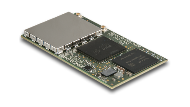
Open-Q 5165RB SOM (System on Module)

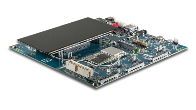
Lantronix has recently launched a system-on-module and its integrated development board based on Qualcomm QRB5165 System-on-Chip running Ubuntu Linux OS. The Open-Q 5165RB system-on-module has been designed with a compact form factor of just 29×50 mm for edge robotics applications. Along with the public launch comes another hardware on the same Qualcomm system-on-chip, but a development board with all the header to explore the functionalities of the modules. System-on-modules are designed in such a way that they feature specialized processing cores for AI processing, image, and graphics processing.

As mentioned earlier, the SOM is built on the Qualcomm QRB5165 System-on-Chip that manufactures using 7nm technology, featuring Kryo 585 Octa-core CPU. The cores run on different clock frequencies: one Kryo Gold prime at 2.84 GHz, three Kryo Gold at 2.42 GHz, and four Kryo Silver at 1.81 GHz. With the powerful processor comes the Hexagon 698 DSP, Adreno 650 GPU, and several other processing units.

A deeper look at the Open-Q 5165RB system-on-module

  • SoC:
    • CPU: Kryo 585 Octa-core CPU
    • DSP: Hexagon 698 DSP with quad Hexagon Vector extensions
    • GPU: Adreno 650 GPU
    • Other processing units: Adreno 665 video processing unit, Adreno 995 display processing unit, NPU230 neural processing unit, and SPU240 secure processing unit
  • Memory: 8GB LPDDR5 @ 2750MHz
  • Wireless Connectivity: 802.11ax 2×2 MU-MIMO + Bluetooth 5.1, Bluetooth Milan ready
  • Video Interfaces: 2x 4-lane MIPI DSI D-PHY 1.2 and DisplayPort v1.4 on USB Type-C
  • Audio Interfaces: 3x 4-lane MIPI CSI camera ports + CCI I2C control
  • I/O interfaces: 4-bit SD 3.0, UART, I2C, I3C, SPI, configurable GPIOs, sensor I/O to dedicated Hexagon sensor DSP
  • Dimensions: 50mm x 29mm
  • Power: Power management and battery charging solutions on SOM
  • OS support: Ubuntu Linux OS

“With Lantronix’s new Open-Q 5165RB SOM, developers gain the perfect computing core needed to accelerate leading-edge robotics application development while reducing time to market.”

says Jacques Issa, VP of Marketing at Lantronix.

Open-Q 865 Development Kit

The system-on-module is expected to be famous for a variety of applications even outside of edge robotics. The expanded support for TensorFlow Lite, Qualcomm Neural Processing SDK, Computer Vision SDK, and Neural Networks API gives us the sense of its power to aid deep learning and neural networks processing applications.

After a launch of the system-on-module, there is always a development kit available along with it. The Lantronix’s new Open-Q 865 SOM Development Kit comes to light to speed up product development and expose all available I/Os.

There are a lot of technical details available on the manufacturer’s page. The system-on-module is priced at $580, while the development kit (without the SOM) is available at $399. Visit the product page for more information.

Würth Elektronik Thetis-I with Evaluation Kit

Radio Module and Test Option for the Wirepas IoT Network Protocol

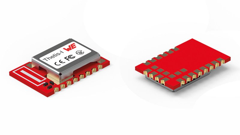
Würth Elektronik launches Thetis-I, a ready-to-use radio module for Wirepas mesh networks. Thetis-I is the perfect solution for IoT device manufacturers. Networks with technology from Wirepas, the Finnish software provider, are self-healing and freely scalable. Each device with a Thetis-I radio module can also act as a router which means no further infrastructure is required for mesh communication. Würth Elektronik offers developers the Thetis-I Evaluation Kit. It contains an evaluation board, a USB radio stick, and three sensor nodes. Thanks to the tailored Wirepas Commander software, this kit can be operated and configured directly via a PC.

Specifications

  • Wirepas routing mesh protocol, optimized for ultra-low energy consumption
  • High scalability: ideal for large IoT networks
  • Low-energy and low-latency modus
  • Remote nodes’ configuration
  • Authentication & Encryption
  • Standalone or host-controlled operation
  • Base or custom firmware solutions
  • Nano SIM size: 8 x 12 x 2 mm
  • Smart antenna configuration (2-in-1 Module)
  • Nordic Semiconductor SoC nRF52840
  • +6 dBm TX power (ERP: 4 dBm)
  • 1 MB flash memory, 256 kB RAM
  • CE, FCC, IC certification
  • Software-Tool: Wirepas commander

Thetis-I is based on the Nordic nRF52840 chipset and the proven proprietary 2.4 GHz radio module. The radio module, optimized for Wirepas networks, is extremely energy-saving and offers the choice between low-energy and low-latency modes. The module, which measures just 8×12×2 mm, can be configured remotely using the freely available Wirepas Commander software. It supports authentication and encryption, stand-alone or host-controlled operation. A wide range of potential applications can be tested using the Evaluation Kit. Wirepas technology enables easy connection to well-known cloud platforms. The slim evaluation board allows a controller board to be connected for developing applications. A battery-powered sensor board equipped with the versatile WSEN-PADS pressure sensor and the WSEN-HIDS humidity sensor readily provides an application example for a mesh network.

Thetis-I and the Evaluation Kit are now available from stock without minimum order quantities. Individualized firmware versions can also be supplied on request.

Fibocom LTE-A Pro Module Series NL952 Accelerates the Digital Journey with T-Mobile Certificate

Fibocom, a global leading provider of IoT (Internet of Things) wireless solutions and wireless communication modules, announces that its LTE Advanced Pro module NL952-NA has been successfully certified by T-Mobile. The module is now qualified to provide wireless connection services under T-Mobile’s network, which further expands the product’s application coverage over the US market.

Based on the Qualcomm Snapdragon X24 chipset, Fibocom’s NL952 is a high-performance LTE-A Pro Cat 20 module series designed to provide high-speed connectivity in applications such as CPE, gateway, TV, VR, drone, etc. Coming with the M.2 form-factor, the Fibocom NL952 module series supports LTE/LAA network bands in addition to UMTS/HSPA+ fallback, which offers maximum data rates of 2Gbps downlink and 150Mbps uplink. With an integrated GNSS receiver (GPS/GLONASS/BeiDou/Galileo), Fibocom’s NL952 module series supports Linux and Android operating systems as well as other functions including VoLTE, Audio, FOTA.

The module also supports various interfaces, including USB 3.0, PCIe 2.0, GPIO, UIM, I2C and MIPI, unleashing the potential of cellular technology to meet high-speed application demand. To date, the Fibocom NL952 module series has been globally certified by regional regulatory bodies and industry institutions, including IC/ FCC/ RoHs/ CE/ GCF/ RCM/PTCRB/ HF.

“We are very excited to announce the NL952-NA module has been certified by T-Mobile,” said Ron Friedman, VP of Americas Sales Dept., Fibocom. “Fibocom continues to enable seamlessly IoT experiences and help to accelerate digital transformation globally. The Fibocom LTE-A module NL952 is capable of offering customers with the best cost performance for a wide range of IoT scenarios.”

For more information, please visit:

Resources

Epishine signs distribution agreement with Farnell to enable light energy harvesting within electronic design

Epishine’s new-to-market printed organic solar cells and development kits remove the need for batteries reducing the impact on the environment.

The innovative Swedish manufacturer of printed organic solar cells and development kits Epishine has signed a new franchise agreement with Farnell, an Avnet Company and global distributor of electronic components, products, and solutions. The new-to-market printed organic solar cells are optimized for harvesting energy from indoor, low energy lighting enabling organic solar power to be used everywhere. Design engineers can utilize this new and innovative technology with Epishine’s Light Energy Harvesting Evaluation Kit. Farnell is the first high-service distributor to stock products from Epishine.

Epishine’s organic solar cells are small, thin, flexible, and printed on recyclable plastic. The cells can be easily integrated into any low-power electronic equipment where they convert ambient indoor light into electricity. New product designers can replace batteries in wireless sensors and similar devices with organic solar cells, reducing the environmental impact of battery waste and saving battery replacement costs.

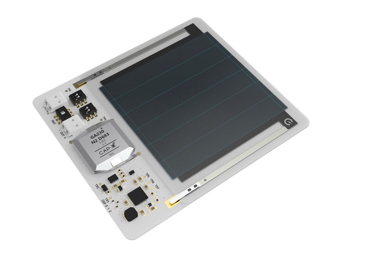
The Light Energy Harvesting Evaluation Kit (EK01LEH3_6) demonstrates how Epishine’s Light Energy Harvesting (LEH) modules can power indoor wireless low-power devices that are usually powered by batteries. It combines a 6-cell 50x50mm LEH module with a supercapacitor which acts as an energy buffer and intelligent charging management system to support various output voltages and energy storage solutions. It can even use an external primary battery as a backup. The evaluation kit can deliver sufficient output current to power most low-power wireless devices such as BLE, Zigbee, and LoRa. The ability to program the evaluation kit provides added flexibility and showcases the unique product integration and design possibilities of Epishine’s LEH modules.

Key features include:

  • Selectable output voltage ranging from 1.8V to 3.3V in 0.1V steps
  • Up to 300mA output current
  • Optimized for indoor use (-20°C to 40°C / 0-85%RH) with illumination intensities of 20 to 1000 lux
  • A supercapacitor for energy storage which can be reconfigured to charge rechargeable battery

Epishine’s organic solar cells will be added to Farnell’s line card later this year. Epishine’s Light Energy Harvesting Evaluation Kit is now available for fast delivery from Farnell and Newark in North America.

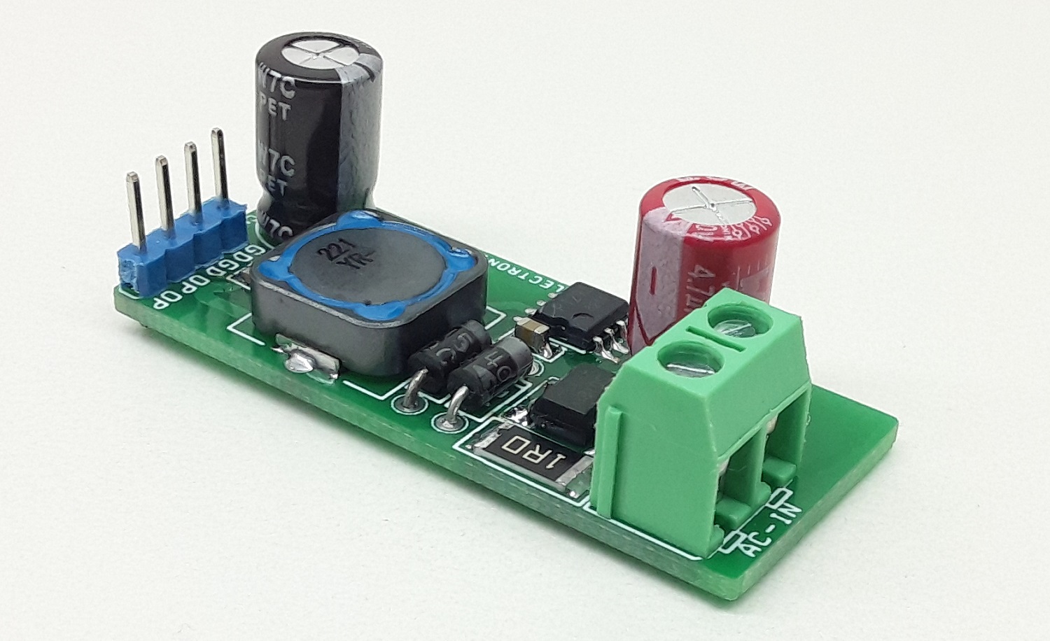
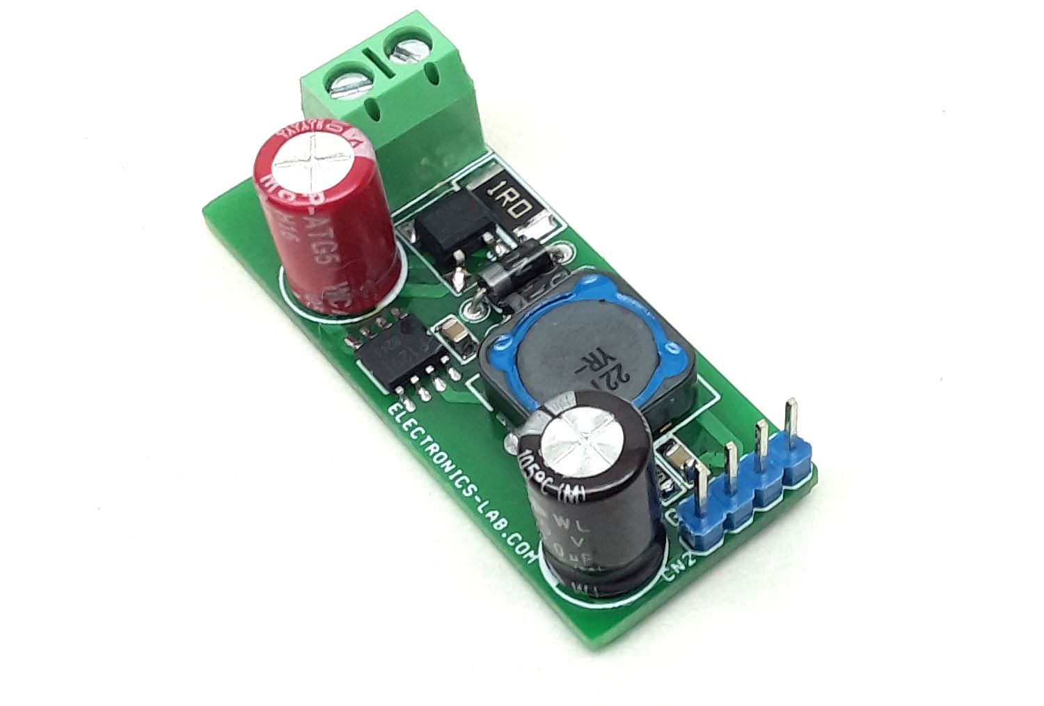
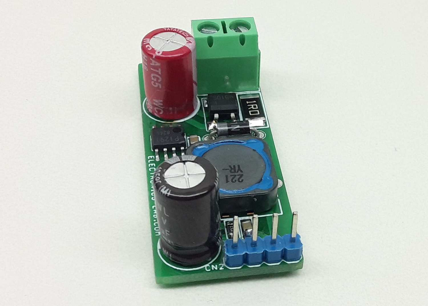
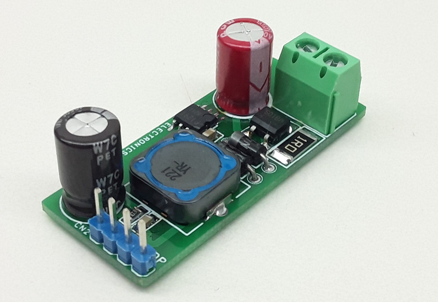
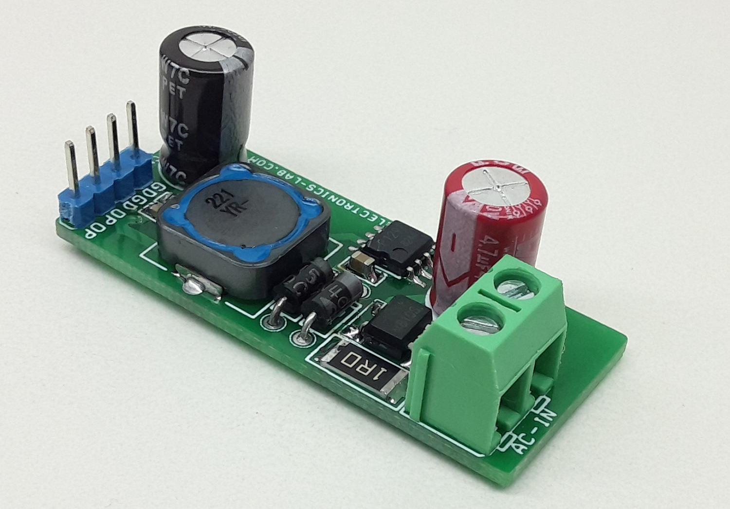
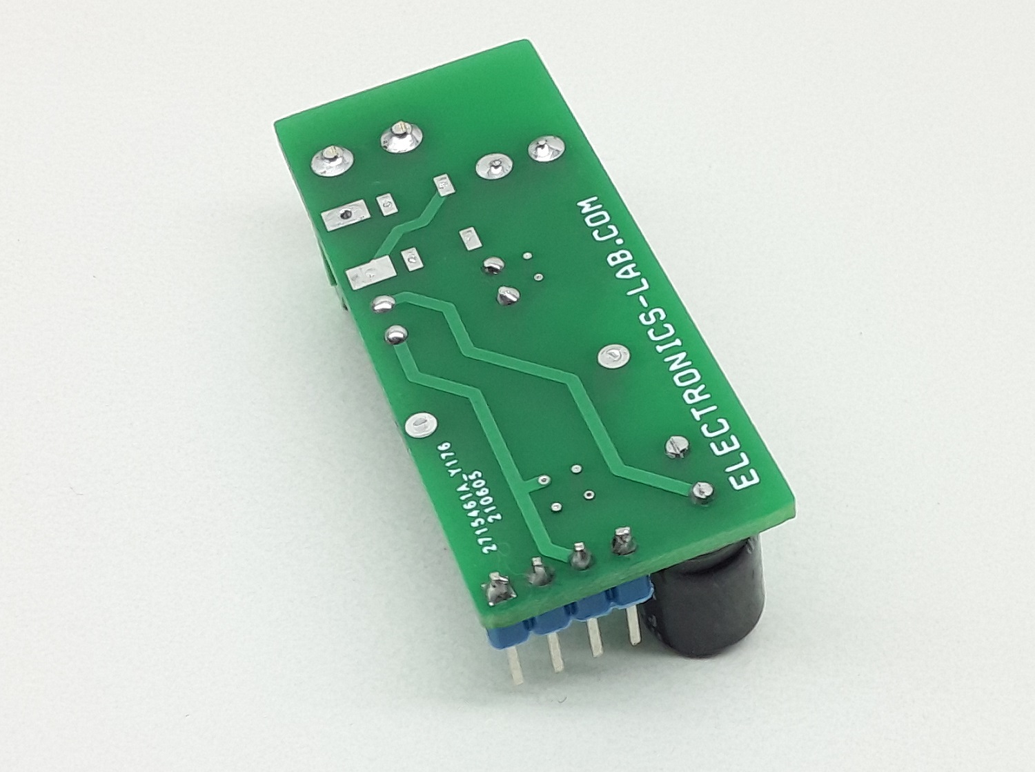
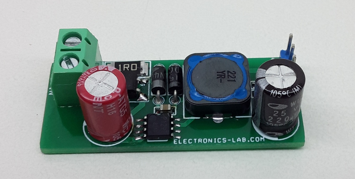
230V AC Input – 12V Output DC Converter, Non-Isolated Buck Converter

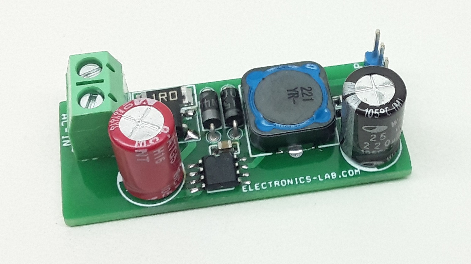
The project described here outputs 12V DC voltage from the input of 230V AC. The output current is up to 100mA.  The project is based on BM2P129TF chip which is PWM method DC/DC converter with a built-in 650V MOSFET. BM2P129TF contributes to low power consumption by built-in a 650V starting circuit. Built-in current detection resistor realizes compact power supply design. Current mode control imposes current limitation on every cycle, providing superior performance in bandwidth and transient response. The switching frequency is 100Khz in fixed mode. At light load, frequency is reduced and high efficiency is realized. Built-in frequency hopping function contributes to low EMI. Low on-resistance 9.5 Ohms 650V MOSFET built-in contributes to low power consumption. The default over current limit of the chip is 450mA.

This project uses lethal AC voltage and should be handled only by qualified personnel familiar with all safety and operating precedes.
Note: The project can also operate with a lower input voltage of 90V AC. The board provides 10.5V and load current 2mA with 90V AC input. The module also can be used as a high voltage DC-DC to DC converter with input range 100V DC to 380V DC, output 10.5V to 13V.

Features

  • Input Supply 230V AC
  • Output 12V DC
  • Load 100mA Constant (Maximum 150mA)
  • Operating Frequency 100kHz Fixed
  • Cycle By Cycle Current Control
  • Efficiency 75%
  • PCB Dimensions: 46.67 x 19.53 mm

Schematic

Connections


Parts List

NOQNTYREFDESCMANUFACTURERSUPPLIERSUPPLIER PART NO
11CN12 PIN SCREW TERMINAL PITCH 5.08MMPHOENIXDIGIKEY277-1247-ND
21CN24 PIN HEADER CONNECTOR PITCH 2.54MMWURTHDIGIKEY732-5317-ND
31C11uF/25V SMD SIZE 0805YAGEO/MURATADIGIKEY
41C2220uF/25V ELECTROLYTICNICHICONDIGIKEY493-15302-ND
51C30.1uF/50V SMD SIZE 0805YAGEO/MURATADIGIKEY
61C44.7uF/400V ELECTROLYTICWURTHDIGIKEY732-8886-1-ND
71D11N4007MICRO COMMERCIALDIGIKEY1N4007MSCT-ND
81D2MDB10SONSEMIDIGIKEYMDB10SFSCT-ND
91D3BA159VISHAYDIGIKEYBA159GP-E3/73GICT-ND
101L1220uH/1.38ABOURNSDIGIKEY118-SRR1260A-221KCT-ND
111R11E 2W SMD SIZE 2512YAGEO/MURATADIGIKEY118-SRR1260A-221KCT-ND
121R210K 5% SMD SIZE 0805YAGEO/MURATADIGIKEY
131U1BM2P129TF SOIC8ROHMDIGIKEYBM2P129TF-E2CT-ND

Gerber View

Photos


Video

BM2P129TF Datasheet

Prodigy PGY-LA-EMBD Logic Analyzer Hands-on Review

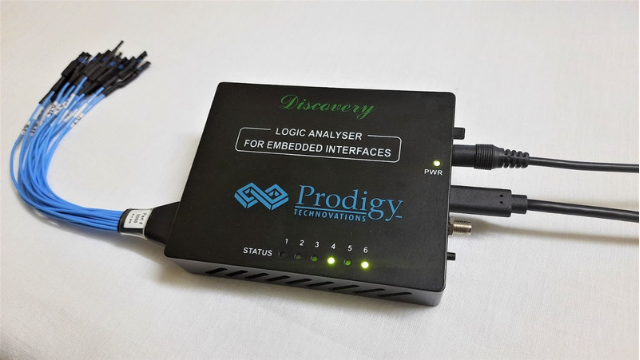
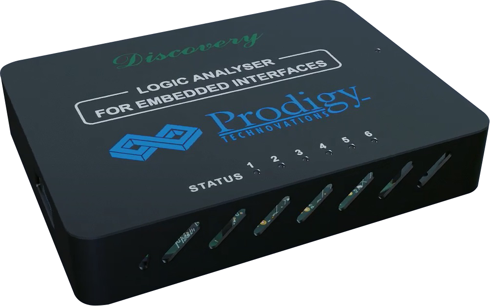
Prodigy Logic Analyser

Since its introduction in 1973 by Hewlett Packard, Logic Analyzers have been one of the most important tools in an engineer’s toolkit. Logic Analyzers enable us to easily debug digital logic signals by capturing the data and plotting it in a time-view format. They serve a similar purpose as an oscilloscope, which is a tool to view analog waveforms. With the advancements in technologies, circuits are becoming much faster and more complex and thus require a high sampling rate to be debugged properly. This created a demand for easy-to-use Logic Analyzers with high speed and low cost, giving rise to surprisingly good USB-based analyzers. In this article, we’ll have a hands-on look at one such Logic Analyzer from Prodigy Technovations, which can provide 1GS/s sampling speed that too on all of its 16 channels.

Prodigy Technovations, the leading provider of innovative protocol analysis solutions, designed and manufactured the Logic Analyzer for Embedded Interfaces. Also identified as PGY-LA-EMBD, these Logic Analyzers can even work as a Protocol Analyzer or both simultaneously. So let’s jump into the review now.
Accessories in the box and build quality

The packaging was quite well done, with all the electronics placed inside anti-static plastic bags. There were a total of five components, including the Logic Analyzer. The very first thing we get our eyes on is the custom 16-channel flying lead probe cable. There are 16 pairs of wires, each pair consisting of a digital wire and a ground wire. The cables are labeled with their corresponding channel number, which is very convenient while connecting to the interface to be debugged. The cable is well insulated with heat shrinks at every pair and surely comes under high quality. Next, we get a C-Type USB cable that is noticeably thicker than the normal ones and a 12W 5V DC power adapter to power the device. In addition to the above, there was also a CD with a software setup and user manual in it.
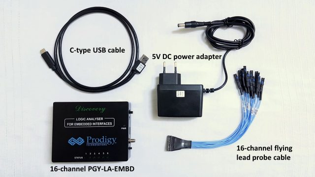
Prodigy Logic Analyser Hands-on Review Components


Talking about the build quality, the housing is a complete metal body, giving it an excellent and robust look. The surface has a nice black matte finish along with the company’s branding on the top. The grills at the front and backside help with cooling and adding to the aesthetics of the device. There are four flat rubber legs at the bottom at each corner, which gives it a little elevation and insulation from the working surface. The PGY-LA-EMBD is compact enough to fit in your palm with a dimension of 140 x 100 x 35 mm. Overall, the build quality of all the accessories and the Logic Analyzer feels very durable.

Hardware specifications

PGY-LA-EMBD comes with a 1GS/s (or 1GHz) asynchronous timing speed and 100MS/s synchronous state speed. Discovery series logic analyzers can perform simultaneous protocol analysis of I2C, SPI, UART, I3C, SPMI, and RFFE interfaces on all the 16-channels in embedded system designs. It comes with an input buffer of 4GB DDR3, which is plenty for storing captured data. There are also some advanced trigger capabilities, including auto, pattern, protocol awareness, and timing.

The supported voltage levels are 1.2V, 1.8V, 2.5V, 3.3V, and 5V, selected in the software tool. There are six green LEDs at the top, which indicate the working status, and a PWR LED to indicate the power ON status. An external trigger can be given using the Trigger Out SMA connector on the right side. Additionally, there’s a USB 3.0 port, 5V power port, an ON/OFF switch, and a reset button on the right side. There are two micro-USB ports on the left, a 14-pin connector that is said to be reserved, and a connector for flying lead cable.

Test setup: ESP32 is connected to a BMP280 sensor via I2C

To try out the Logic and Protocol Analyzer modes of PGY-LA-EMBD, I decided to build a setup that would be simple and, at the same time, will operate somewhat at a frequency of 300KHz. My setup consists of an ESP32 DevKit v4 hooked to a BMP280 temperature and pressure sensor via I2C. The ESP32 acts as a master, whereas the sensor acts as a slave. I will try to sniff the Serial Data (SDA) and Serial Clock (SCL) lines while the sensor sends the data.
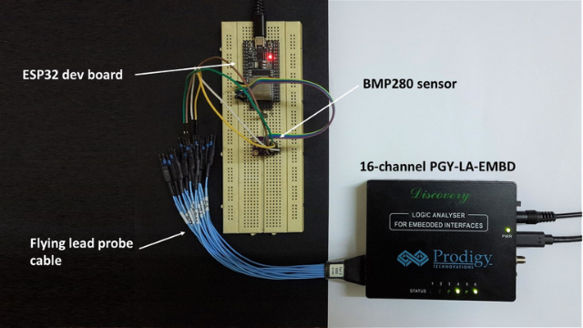
Prodigy Logic Analyser Hands-on Review Connections

Channel 1 of Logic Analyzer is connected to SDA, and channel two is connected to SCL. The overall setup is quite simple, and everything worked on the first try itself. While this setup doesn’t really do the justice of testing the Logic Analyzer’s high-speed capabilities, it does the job for now.

Software tool

Once the Logic Analyzer is connected to the PC through a USB interface, the software handles the rest of the work of analysis and data representation. The setup is around 14MB which, after installation, takes up to 50MB of disk space. So, it’s lightweight software, which, when opened directly, greets you with the Logic Analyzer setup page. After clicking the “Connect” button, a message displaying “Device connected” pops up, and we’re now ready to capture signals. I selected the Logic and Protocol Analysis mode, a sampling rate of 500MS/s, I2C as the protocol, and finally, channels 1 and 2 as SDA and SCL, respectively.
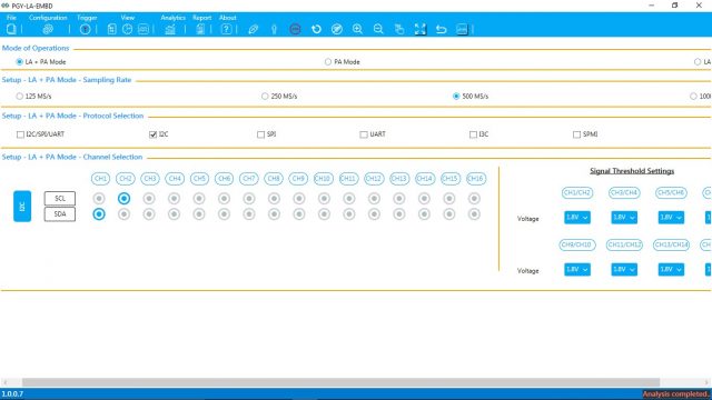
We need to click the Acquire button with the setup done and the Logic Analyzer will start capturing data. On the Logic Analyzer, LED 1 will now start glowing, indicating that the capture has started. Simultaneously, the software will keep on displaying the acquired data, so you won’t have to wait until the end to get the results. The data will keep on streaming to your PC until you click on the Stop button. LED 1 will be turned off and LED 4 will glow, indicating that capture has stopped.

After capturing the signals, the PGY-LA-EMBD software tool provides a total of three options for viewing – Protocol View, Timing View, and Logic View. Protocol View provides decoded packet information and error information, if any, along with a bus timing view at the bottom. Timing View gives in-depth insights about timing information. Logic View displays the actual state of signals, i.e. High or Low, in a time-correlated format. The interface should be quite familiar if anyone has used a Logic Analyzer before.
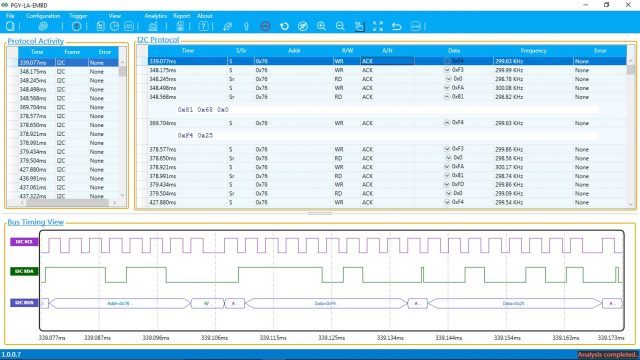
If we look into the table, the 0x76 in the Addr column is the I2C address of the BMP280 sensor. We first wrote a value of 0xF4, requesting the sensor to give out the readings. The sensor acknowledges the ESP32, which can be seen as ACK under the A/N column. After that, the sensor writes out 0x81, 0x68, and 0x0, representing the raw readings coming straight out of the registers in the sensor. Even the waveform at the bottom shows what type and value of data were transmitted at each instance of time.

Final thoughts

To sum up, the whole process of getting started with the PGY-LA-EMBD Logic Analyzer and capturing the data did not take much time; in fact, writing this article took a longer time than this. The labeling on the probe cables helped a lot as normally I would check the connections 3-4 times to make sure nothing is wrong. The software GUI is pretty straightforward and displays all the important stuff on a single page.

While operating, the PGY-LA-EMBD Logic Analyzer does heat up a little bit, and it is more noticeable with the full metal body. However, it is not a major concern as the grills on the front and back dissipates the heat passively. For an end-user, the hefty price tag of $1500 of the PGY-LA-EMBD can be justified with a trove of features. This includes 1GS/s sampling speed, support for I3C, RFFE, and SPMI protocols through a software upgrade in the future (field upgradable), offline decoding capabilities, and also Python API support. So, it can be termed as a future-proof product and seems to be worth investing in.

You can learn more about PGY-LA-EMBD Logic Analyzer on its product page or request a demo before buying one.
TOP PCB Companies