Microchip Technology has released 24CS512, the first commercially available I2C Serial EEPROM with support for 3.4 Mbit/s data rates. This high-speed I2C EEPROM is 3 to 4 times faster than the existing EEPROMs available in the market. It offers high-speed mode operation, software write-protection and factory programmed serial numbers.
The 24CS512 I2C Serial EEPROM provides 512 Kbits of Serial EEPROM, utilizing an I2C (two-wire) serial interface with high-speed mode capability. The device is organized as 65,536 bytes of 8 bits each (64 Kbytes) and is optimized for use in consumer and industrial applications where reliable nonvolatile memory storage is essential. It allows up to eight devices to share a common I2C (two-wire) bus and is capable of operation across a broad voltage range (1.7V to 5.5V).
This high-speed mode I2C serial EEPROM expands the available options for meeting complex design criteria. The device also contains a Configuration register, which allows the write protection behavior to be configured for legacy hardware write protection or enhanced software write protection which allows the user to protect any of the eight independent 64-Kbit zones.
Product Features
64K x 8 (512 Kbit)
2-Wire Serial Interface, I2C™ Compatible
3.4MHz High Speed Mode Capable
Operating voltage 1.7V to 5.5V
Pre-programmed 128-bit serial number
User-programmable, lockable 128-byte ID page
Enhanced Software Write Protection
Hardware Write-Protect Pin
Built-in Error Correction Code (ECC) Logic
Page Write Time 5 ms Max.
Standby current 1 uA, max.
Cascadable up to Eight Devices
Pb-Free and RoHS Compliant
Factory Programming Available
The 24CS512 makes managing your data easy with its software write protection, lockable ID page, and pre-programmed 128-bit serial number. Traditional I2C EEPROMs utilize hardware-based write protection that only allows locking or unlocking the entire memory array via an external pin, which severely limits the possible ways to protect data. The 24CS512 retains this legacy feature, but also divides the memory array into 8 different zones and provides the ability to individually write protect any combination of zones via software.
Additionally, each 24CS512 comes pre-programmed from our factory with a globally unique 128-bit serial number that can be used by customers as a unique product identifier. This serial number can eliminate the time-consuming step of performing and ensuring the serialization of a product on and across multiple manufacturing lines.
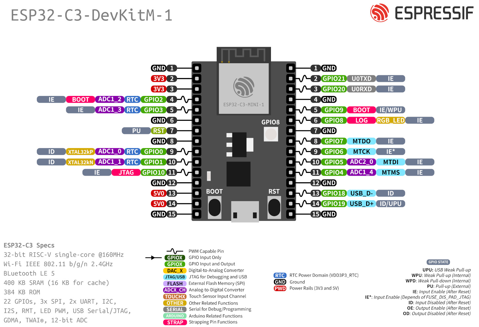
In this article, we will explore another onboard functionality of Espressif’s ESP32-C3-DevKITM-1 which is the onboard RGB LED. With its powerful connectivity, compact size at such a low cost the ESP32-C3- DevKit M-1 board is a must-try for your next IoT project. You can read the official documentation of the development board as well.
The board features an onboard addressable RGB LED (WS2812), driven by GPIO8 which can be configured to glow in different colors based on the RGB value of the color given. ESP-IDF being the native software development framework for ESP boards with all API, Toolchain scripts are preinstalled. In this article, we focus on the programming of ESP32-C3 using ESP-IDF.
We will program the ESP32-C3-DevKITM-1 module for the following blink applications:
1. Single Blink LED Use Case on ESP32-C3-DevKITM-1
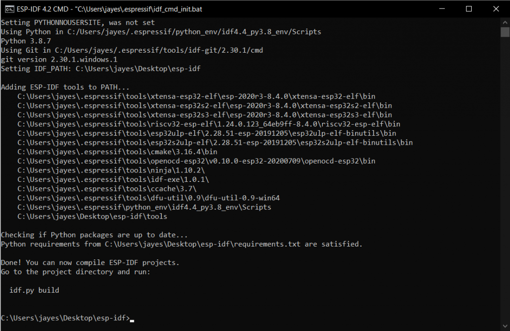
Step1: Launch your ESP-IDF CMD Application.
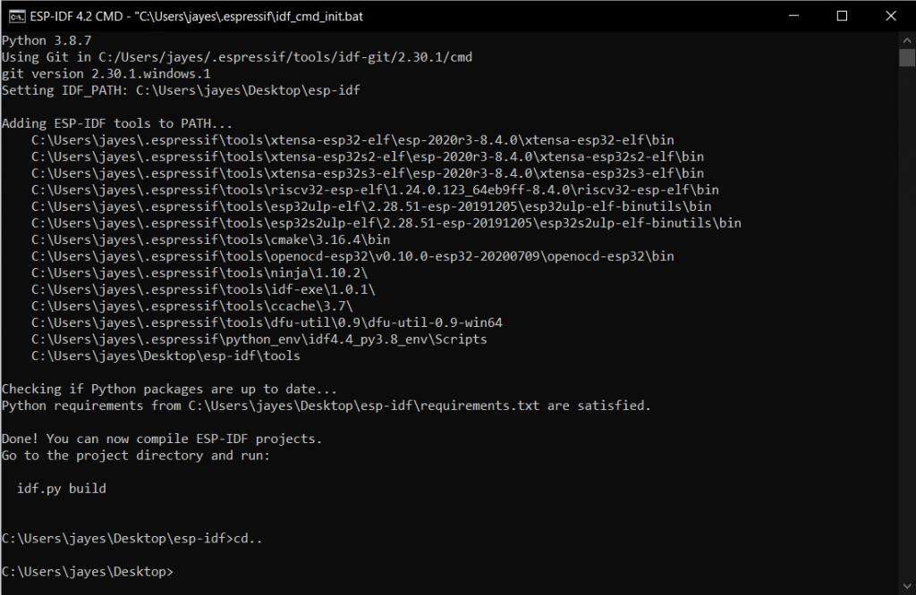
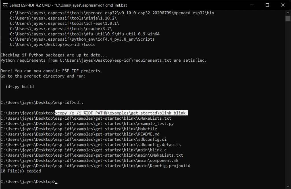
Step2: By default, you will be in the esp-idf home directory, change the directory by using cd.. command.
Step3: Use xcopy /e /i %IDF_PATH%\examples\get-started\blink blink command. This makes a copy of the blinking folder situated in the examples folder of the esp-idf home directory in the current location.
Step4: Switch to the newly created folder using the cd blink command.
Step5: Execute idf.py set-target and idf.py menuconfig commands to make the program compatible with the board you have.
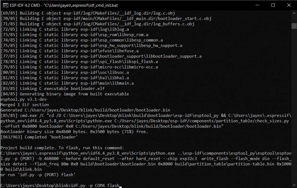
Step6: Now build the program using the idf.py build command.
Step7: Connect your esp board now and flash the program using idf.py -p (PORT) flash. Here (PORT) is the Port at which your board is connected. This can be found using the device manager on your PC.
Once the flashing is complete, you’ll get a Done message as shown below.
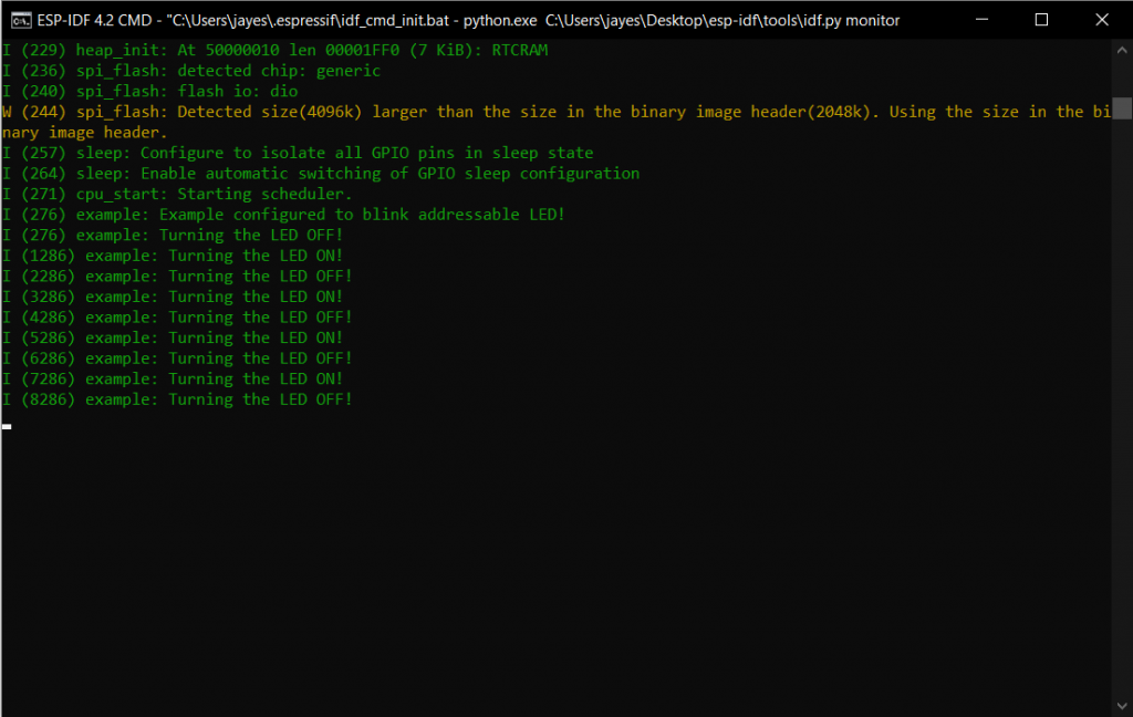
Now, your Onboard LED of the ESP32 C3 board should start blinking white. The Idf.py monitor command gives the real-time status of the LED from the board.
2. LED Colour and Pattern on ESP32-C3-DevKITM-1
As our ESP32 C3 DevKITM-1 board has an RGB LED, we’ll now see how to configure it to the desired color. In order to do so, follow Step3 of the previous single blink example.
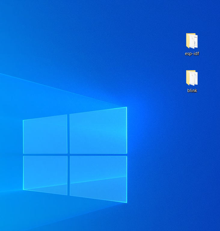
Step4: Now, navigate to the newly created blink folder in file explorer. Here, in our case, the new blink folder was made on the Desktop.
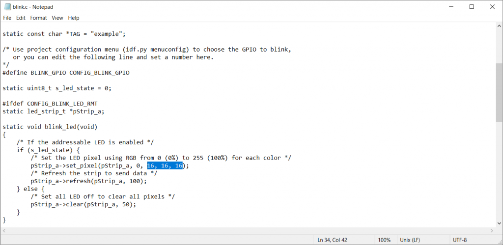
Step5: Open blink -> main -> blink.c file in any suitable application as per your preference. Here, we used the Notepad application to open and edit the blink.c file.
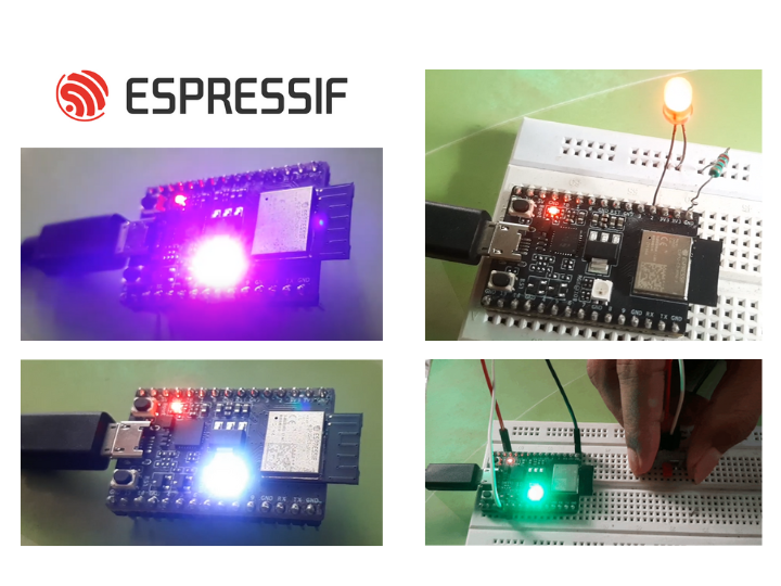
As instructed from the given comments, the highlighted values in the above figure are the RGB values of the glowing LED. Set these values as required, to obtain your desired color as the output. We set these values to 255, 0, 255 to obtain Magenta Colour. Save the file.
Step6: Come back now to your ESP-IDF CMD Application and execute step4 to step7 of the previous single blink example. Now, your Onboard LED of the ESP32 C3 board should start blinking magenta and can be monitored by the Idf.py monitor command.
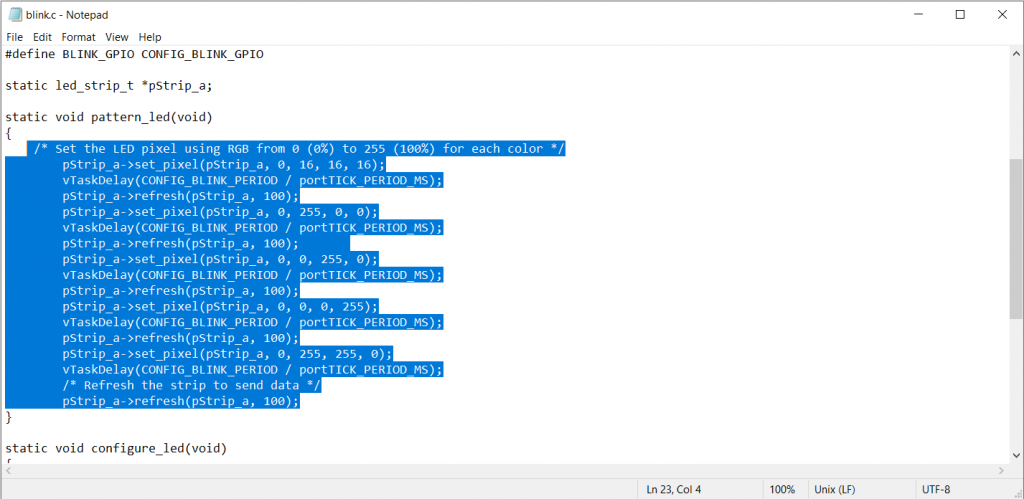
The same logic was followed in order to write a program to make the onboard LED glow in a color pattern.
Code LED pattern
/* LED Pattern Example
Makes the Onboard LED of ESP32-C3-DevKITM-1 glow in colour pattern from White -> Red -> Green -> Blue -> Yellow
*/
#include <stdio.h>
#include "freertos/FreeRTOS.h"
#include "freertos/task.h"
#include "driver/gpio.h"
#include "esp_log.h"
#include "led_strip.h"
#include "sdkconfig.h"

#define BLINK_GPIO CONFIG_BLINK_GPIO
static led_strip_t *pStrip_a;

static void pattern_led(void)
{
/* Set the LED pixel using RGB from 0 (0%) to 255 (100%) for each color */
pStrip_a->set_pixel(pStrip_a, 0, 16, 16, 16);
vTaskDelay(CONFIG_BLINK_PERIOD / portTICK_PERIOD_MS);
pStrip_a->refresh(pStrip_a, 100);
pStrip_a->set_pixel(pStrip_a, 0, 255, 0, 0);
vTaskDelay(CONFIG_BLINK_PERIOD / portTICK_PERIOD_MS);
pStrip_a->refresh(pStrip_a, 100);
pStrip_a->set_pixel(pStrip_a, 0, 0, 255, 0);
vTaskDelay(CONFIG_BLINK_PERIOD / portTICK_PERIOD_MS);
pStrip_a->refresh(pStrip_a, 100);
pStrip_a->set_pixel(pStrip_a, 0, 0, 0, 255);
vTaskDelay(CONFIG_BLINK_PERIOD / portTICK_PERIOD_MS);
pStrip_a->refresh(pStrip_a, 100);
pStrip_a->set_pixel(pStrip_a, 0, 255, 255, 0);
vTaskDelay(CONFIG_BLINK_PERIOD / portTICK_PERIOD_MS);
/* Refresh the strip to send data */
pStrip_a->refresh(pStrip_a, 100);
}
static void configure_led(void)
{
/* LED strip initialization with the GPIO and pixels number*/
pStrip_a = led_strip_init(CONFIG_BLINK_LED_RMT_CHANNEL, BLINK_GPIO, 1);
/* Set all LED off to clear all pixels */
pStrip_a->clear(pStrip_a, 50);
}
void app_main(void)
{
/* Configure the peripheral according to the LED type */
configure_led();

while (1) {
printf(" LED Pattern!");
pattern_led();
vTaskDelay(CONFIG_BLINK_PERIOD / portTICK_PERIOD_MS);
}
}
The Led now glows from White -> Red -> Green -> Blue -> Yellow as seen from the video.
The delays for the pattern or even for the blink examples can be set from the vTaskDelay() lines.
For example, setting these delays provides us with the following output.
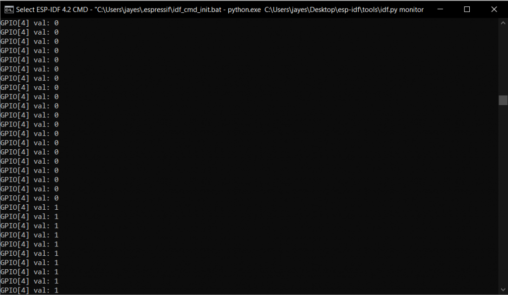
3. Controlling Onboard LED of ESP32-C3-DevKITM-1 Using External Switch
This example is basically a combination of Single blink and LED pattern examples. The board will choose from either of these examples based on an external input switch. An if-else structure is implemented here.
Components:
ESP32-C3-DevKitM-1
Breadboard
Switch (button)
Jumper cables
USB 2.0 cable
As and when the input on pin 4 of the ESP32-C3-DevKitM-1 board becomes high (1), the LED color pattern example is executed, and else i.e. on low input (0), the Single blink example is executed.
Code can be found below:
#include <stdio.h>
#include "freertos/FreeRTOS.h"
#include "freertos/task.h"
#include "driver/gpio.h"
#include "esp_log.h"
#include "led_strip.h"
#include "sdkconfig.h"

static const char *TAG = "example";
/* Use project configuration menu (idf.py menuconfig) to choose the GPIO to blink,
or you can edit the following line and set a number here.
*/

#define BLINK_GPIO CONFIG_BLINK_GPIO
#define LED 18
#define IN 1
static uint8_t s_led_state = 0;
static int input=0;
static led_strip_t *pStrip_a;

static void blink_led1(void)
{
if (s_led_state) {
/* Set the LED pixel using RGB from 0 (0%) to 255 (100%) for each color */
pStrip_a->set_pixel(pStrip_a, 0, 16, 16, 16);
/* Refresh the strip to send data */
pStrip_a->refresh(pStrip_a, 100);
} else {
/* Set all LED off to clear all pixels */
pStrip_a->clear(pStrip_a, 50);
}
s_led_state=!s_led_state;
}

static void blink_led2(void)
{
{
/* Set the LED pixel using RGB from 0 (0%) to 255 (100%) for each color */
pStrip_a->set_pixel(pStrip_a, 0, 16, 16, 16);
vTaskDelay(CONFIG_BLINK_PERIOD / portTICK_PERIOD_MS);
pStrip_a->refresh(pStrip_a, 100);
pStrip_a->set_pixel(pStrip_a, 0, 200, 16, 16);
vTaskDelay(CONFIG_BLINK_PERIOD / portTICK_PERIOD_MS);
pStrip_a->refresh(pStrip_a, 100);
pStrip_a->set_pixel(pStrip_a, 0, 16, 200, 16);
vTaskDelay(CONFIG_BLINK_PERIOD / portTICK_PERIOD_MS);
pStrip_a->refresh(pStrip_a, 100);
pStrip_a->set_pixel(pStrip_a, 0, 16, 16, 200);
vTaskDelay(CONFIG_BLINK_PERIOD / portTICK_PERIOD_MS);
pStrip_a->refresh(pStrip_a, 100);
pStrip_a->set_pixel(pStrip_a, 0, 200, 200, 16);
vTaskDelay(CONFIG_BLINK_PERIOD / portTICK_PERIOD_MS);
/* Refresh the strip to send data */
pStrip_a->refresh(pStrip_a, 100);
}
}
static void configure_led(void)
{
ESP_LOGI(TAG, "Example configured to blink addressable LED!");
/* LED strip initialization with the GPIO and pixels number*/
pStrip_a = led_strip_init(CONFIG_BLINK_LED_RMT_CHANNEL, BLINK_GPIO, 1);
/* Set all LED off to clear all pixels */
pStrip_a->clear(pStrip_a, 50);
gpio_set_direction(LED, GPIO_MODE_OUTPUT);
gpio_set_direction(IN, GPIO_MODE_INPUT);
}


void app_main(void)
{

/* Configure the peripheral according to the LED type */
configure_led();

while (1) {

input=gpio_get_level(4);
printf("GPIO[%d] val: %d\n", 4, input);
if(input==0){
blink_led1();
gpio_set_level(LED, s_led_state);
vTaskDelay(500/ portTICK_PERIOD_MS);
}
else{
blink_led2();
gpio_set_level(LED, s_led_state);
vTaskDelay(500/ portTICK_PERIOD_MS);
}
}
}
4. External LED Blink Use Case on ESP32-C3-DevKITM-1
Apart from the onboard RGB led, we can also set an externally connected led to blink. Here, the external LED is connected to pin 2 of the ESP32-C3-DevKitM-1 board.
Components:
ESP32-C3-DevKitM-1
Breadboard
LED
A series resistor ( 220 Ω)
Jumper cables
USB 2.0 cable
The Code can be found below:
/* External LED Blink
Blink Example configured to blink GPIO LED
*/
#include <stdio.h>
#include "freertos/FreeRTOS.h"
#include "freertos/task.h"
#include "driver/gpio.h"
#include "esp_log.h"
#include "led_strip.h"
#include "sdkconfig.h"

static const char *TAG = "example";

/* Use project configuration menu (idf.py menuconfig) to choose the GPIO to blink,
or you can edit the following line and set a number here.
*/
#define BLINK_GPIO 2

static uint8_t s_led_state = 0;

static void blink_led(void)
{
/* Set the GPIO level according to the state (LOW or HIGH)*/
gpio_set_level(BLINK_GPIO, s_led_state);
}

static void configure_led(void)
{
ESP_LOGI(TAG, "Example configured to blink GPIO LED!");
gpio_reset_pin(BLINK_GPIO);
/* Set the GPIO as a push/pull output */
gpio_set_direction(BLINK_GPIO, GPIO_MODE_OUTPUT);
}


void app_main(void)
{

/* Configure the peripheral according to the LED type */
configure_led();

while (1) {
ESP_LOGI(TAG, "Turning the LED %s!", s_led_state == true ? "ON" : "OFF");
blink_led();
/* Toggle the LED state */
s_led_state = !s_led_state;
vTaskDelay(CONFIG_BLINK_PERIOD / portTICK_PERIOD_MS);
}
}
If you are new to the ESP32-C3-DevKITM-1 development board, you can visit the following articles to get a better understanding of it.
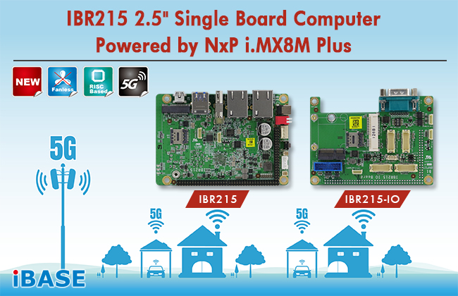
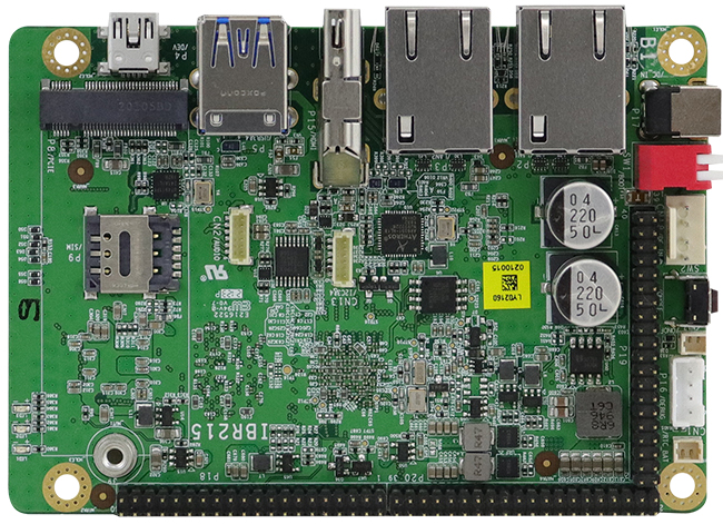
IBASE Technology Inc., a world leading provider of embedded computing systems is pleased to launch the IBR215 2.5-inch single-board computer powered by NXP’s quad-core 1.6GHz ARM Cortex®-A53 i.MX 8M Plus processor. Measuring 105 x 72 mm in a compact footprint, the SBC offers impressive computing performance, advanced multimedia, flexible connectivity and a variety of interfaces, making it ideal for industrial automation, smart home and buildings, smart cities and factories, retail environment, machine learning, and industrial IoT applications.
IBR215 SBC
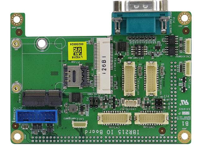
The IBR215 features multiple display interface (HDMI and dual-channel LVDS), a 5G-compatible M.2 3052 socket, 3GB LPDDR4 system memory, up to 64GB eMMC flash memory, external I/O including one HDMI 2.0a, two USB 3.0, two GbE RJ45, one USB OTG, and an SD socket, as well as internal headers for two I2C and DC power. Three 2×20 headers on board connect communication and GPIO signals to the IBR215-IO expansion board to provide interfaces for an M.2 E-key socket, an mPCIe socket, one RS232/422/485 port, two USB 3.0, dual-channel LVDS with backlight control, two CAN bus and two MIPI camera serial interface.
IBR215-IO
IBR215 FEATURES:
NXP Cortex®-A53, i.MX 8M Plus Quad 1.6GHz processor
The IBR215 has a wide operating temperature range of -40°C~85°C when built with a heat sink or housing with efficient heat dissipation. IBASE offers both Yocto Linux and Android BSP (Board Support Package) to enable customers to easily develop their applications. For more information, please visit www.ibase.com.tw.
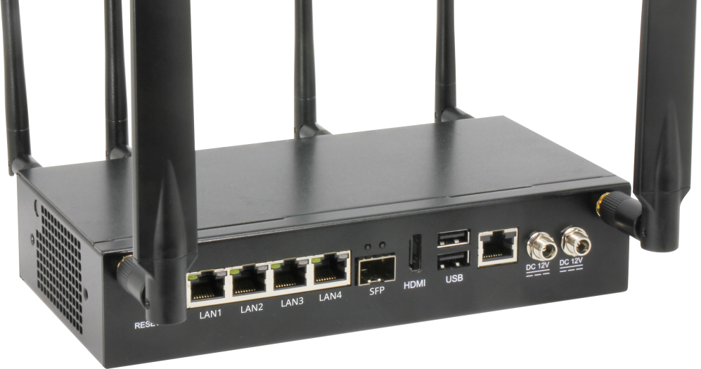
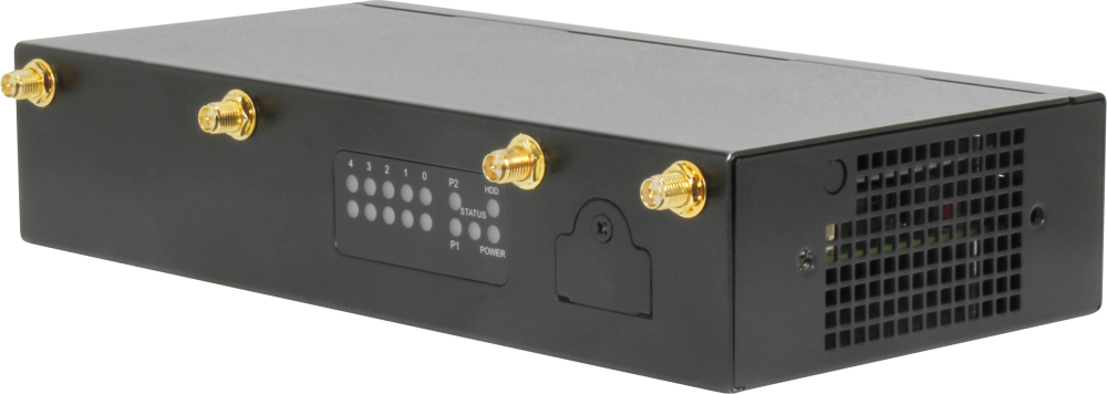
The FWS-2280 is a powerful, compact white box solution for network applications such as SD-WAN and UTM, powered by the Intel® Atom™ x6000E series processors.
AAEON, a leader in uCPE white box solutions, announces the FWS-2280 desktop network appliance. Powered by the Intel® Atom x6000E, Celeron® and Pentium® N and J series processors (formerly Elkhart Lake), the FWS-2280 brings performance, flexibility, and a host of technologies designed to power network applications including UTM, Firewall, SD-WAN, VPN and more.
The FWS-2280 is powered by the latest Intel® Atom x6000E, Celeron® and Pentium® N and J series processors, combined with up to 32 GB of RAM, allowing the system to handle intensive networking applications. The Intel processor helps bring a host of technologies designed for more secure encryption and faster, more accurate connections, such as Intel® AES-NI.
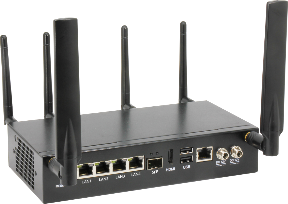
Designed for faster, more flexible connections, the FWS-2280 offers the features and support to power any network deployment. The system comes standard with four copper Gigabit RJ-45 LAN ports and one fiber SFP port, allowing fast, direct connections. The FWS-2280 provides ultimate flexibility for wireless networks with six antenna ports and three Mini PCIe slots (co-lay with M.2), allowing up to three expansion modules to be installed at the same time. This allows for the deployment of either multiple overlapping Wi-Fi and Bluetooth networks, as well as support for cellular WWAN deployments utilizing 4G and 5G communication.
The FWS-2280 is built with several features to help deliver more functionality and more reliable networking. The system features a redundant power supply to help keep networks connected even if one power source fails. It also features a 2.5” SATA drive bay to help power local network storage needs.
“The FWS-2280 is designed to deliver a network solution which provides faster, safer, more accurate data transfer,” said Caridee Hung, Product Manager with AAEON’s Network Systems Division. “The support for multiple wireless connections, including 5G, makes it perfect for deployment in areas with unreliable physical internet connections; and the Intel Atom x6000E processors power modern network applications including Unified Threat Management and SD-WAN.”
AAEON offers a range of manufacturing services that can customize the layout of network systems, ensuring network managers and service providers have exactly the solution they need, from powering Work From Home with VPN and Firewall technology to providing a uCPE white box platform for secure SD-WAN networks.
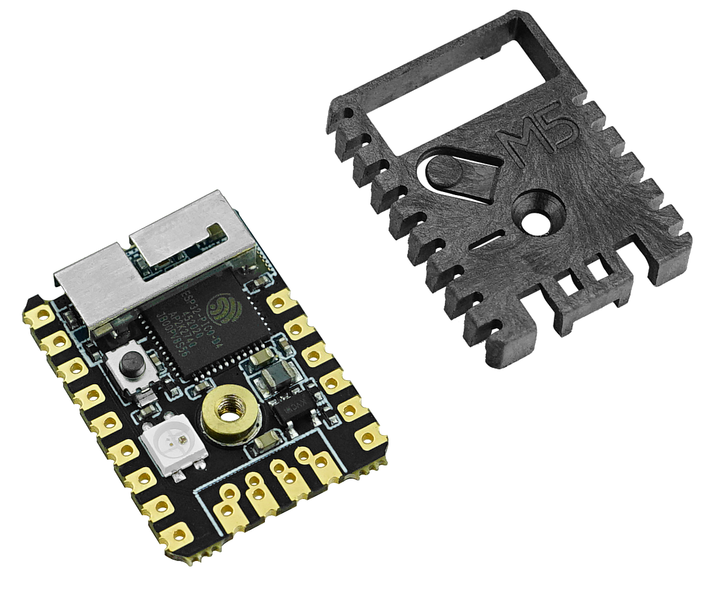
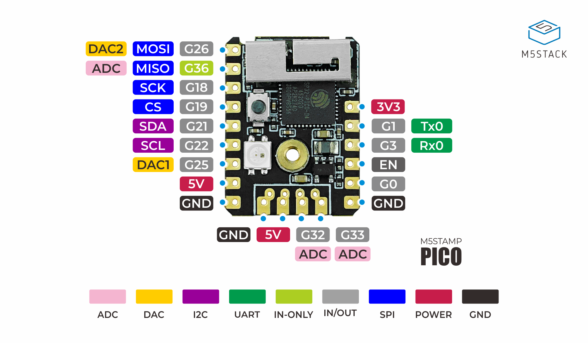
STAMP PICO features an ultra-compact design with two low-power Xtensa® 32-bit LX6 microprocessors at 240MHz on a PCB as tiny and delicate as a postage stamp.
It is ideal for any space-constrained or battery-powered devices such as wearables, home automation, smart sensors, and other IoT devices.
MULTIPLE STYLE: 5 options of installation, means endless possibilities! (SMT, DIP, flywire, Grove interface), with a high-temperature resistant plastic shell, 3D antenna and components can be better protected.
LOW-CODE DEVELOPMENT: STAMP PICO supports UIFlow graphical programming platform, scripting-free, cloud push; and fully compatible with Arduino, MicroPython, ESP32-IDF, and other mainstream development platforms to quickly build various applications.
HIGH INTEGRATION: STAMP PICO contains 5V->3.3V DC/DC design, GPIOx12, programmable RGB LED x1, button x1, finely tuned RF circuit, providing stable and reliable wireless communication.
STRONG EXPANDABILITY: Easy access to M5Stack’s hardware and software ecology system: a wealth of sensors, actuators, functional modules, and accessories to choose from, Extremely fast adaptation.
Product Features
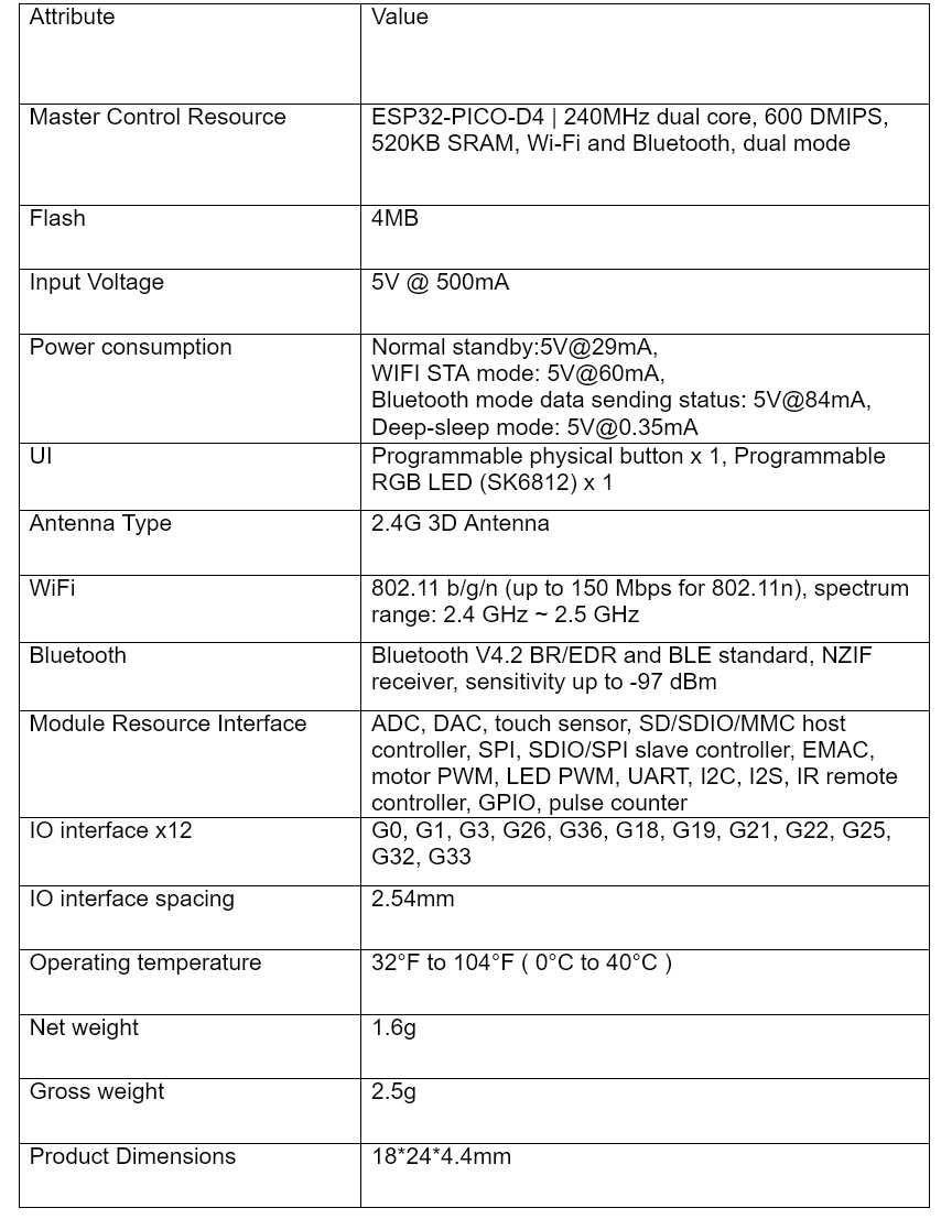
Chip-set: ESP32-PICO-D4 (2.4GHz Wi-Fi and Bluetooth dual mode)
Support UIFlow graphical programming
Support multiple installation style (SMT, DIP, fly-by-wire)
Integrated programmable RGB LED and button
Miniature in size
Specifications
Applications
Instrumentation
Wi-Fi Remote Monitoring/Control
Smart Home
Color LED Control
Fire/security intelligent integrated management
Smart Card Terminal
Wireless POS
Program Download
STAMP PICO adopts the most streamlined circuit design, so it does not include the program download circuit. Users can choose M5Stamp Pico DIY Kit to download the program.
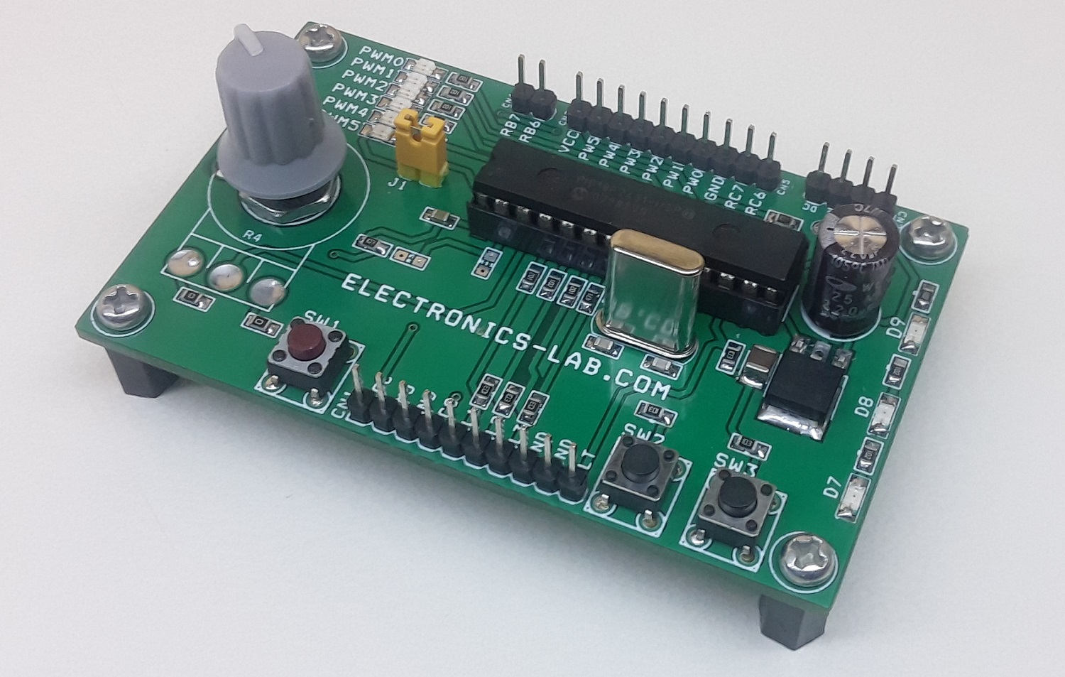
The project described here is a pre-driver for brushless motors with a hall sensor. The board incorporates many features like current monitor, fault, speed control, direction control motor start/stop using tactile switches, various function LEDs, 6 PWM LEDs. By combining it with a hybrid IC or IPM module large size high voltage and high current motor can be driven. The project is compatible with the Microchip PICDEM MCLV motor development board, HEX firmware of the MCLV board can directly work with this board. This board is mainly targeted to control brushless DC (BLDC) motors in hall sensor operations. The board supports a free, ready-to-use MC-GUI (Motor Control – Graphical User Interface) from Microchip. Using the MC-GUI, the user can easily set and/or change motor parameters. This greatly helps the user in developing customized drive solutions. Temperature sensor chip U3 is optional so do not populate. The fault pin has to be high for normal operation, bring it to GND to disable the operations. This pin can be used as over current input from ITRIP pin or an over-current comparator of the IPM module. Overcurrent can be monitored using the IMO (RA0) pin of IC in the range 0 to 3V. PWM Frequency default 20Khz with example HEX code. Hex code is available as a download.
Development board for Brushless Motor, DC Brushed Motor, AC Motors (Pre-Driver) – [Link]
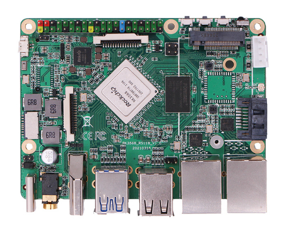
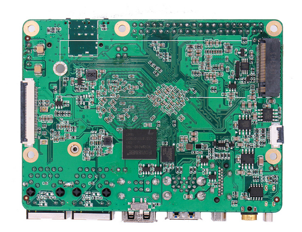
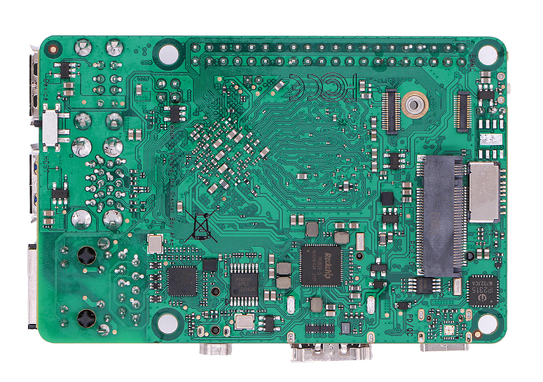
Radxa has announced a Rock 3 Model B SBC, which features the same RK3568 as the Rock 3A, and additionally features WiFi/BT, a second GbE port, native SATA, and M.2 B-key and SIM slots for 4G/5G instead of E-key. The Model B enables native SATA and dual GbE ports, offering enhanced support for NAS and networking applications.
The Rock 3 Model B is seemingly based on the Pico-ITX form factor, but with little tweaks, which makes Radxa call it the Pi-Co ITX. According to Radxa, the 100 x 75mm board should be large enough to fit an M.2 2242 LTE/5G module or 2230 WiFi module and also mount an M.2 2280 SSD module without needing the raised adapter board which the Rock 3A and Rock Pi 4 uses.
The Rock 3 Model B shares some specs with the Rock 3A, which includes the up to 2.0GHz, quad -A55 Rockchip RK3568, which features a Mali-G52 EE GPU and a 0.8-TOPS NPU. The Rock 3B also enables up to 8GB LPDDR4 with 3200MT/s throughput, and it is fitted with an empty eMMC slot. It is also equipped with 2x USB 3.0, 2x USB 2.0, and a USB Type-C port with QC/PD power support. The Rock 3B offers a native SATA interface instead SERDES multiplexing like the Rock 3A
The Rock 3B utilizes the SDIO to provide onboard WiFi. The company replaces the M.2 E-key slot for WiFi with an M.2 B-key slot, which will support 4G/5G with the help of a SIM card slot, and also SSDs. Like the Rock 3B features an M.2 M-key slot that supports NVMe with PCIe 3.0 x2. The Rock 3B also enables an HDMI 2.0 port, audio jack, and RTC with the battery connector. The Rock 3 Model B offers Debian 10 image just like the Rock 3A, and shipment starts in volume around late August. The Radxa boards are available with schematics and other open-source resources and are community-backed.
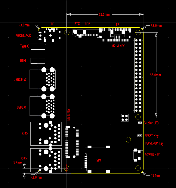
The following are the benefit of the Rock 3B:
All major ports are located at the same side(the rear side)
Front side is for user interactive area such as power buttons, user keys, IR
Board size is big enough for future expansion such as 16G/32G on board memory
Compatible with Pi 40P header and mounting holes
Board size is big enough to hold 2280 SSD
Board size is big enough for multiple USB or multiple ethernets or multiple displays
Board size is big enough for M.2 2242 LTE/5G modules or 2230 WiFi cards, TPU cards
Single-board computers (SBCs) are becoming more popular as the industry develops and new technologies emerge, such as the Internet of Things (IoT). Therefore, the use of computers and smart technologies in electronics has maximized the growth potential of the global SBC market. Technology advancements, such as artificial intelligence, have made the hardware increasingly sophisticated and compact. Hence, with the increasing popularity of SBCs and their powerful features, many third-party manufacturers have come up with hardware based on the Raspberry Pi form factor.
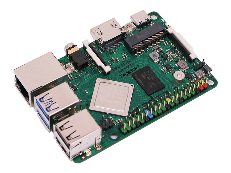
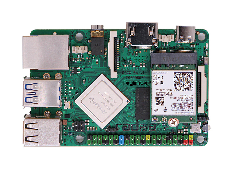
Recently, we have seen the launch of Radxa’s Rock Pi 4 SBC built around the Rockchip RK3599 chip. To continue the emergence of Rockchip-powered development boards, the RK3568-based ROCK 3A is another single-board computer by Radxa. These systems on a chip are very versatile and capable of executing various extensive tasks.
ROCK 3A is a more powerful version of ROCK Pi 4 with a few new interfaces. Hence, as compared to the previous Rockchip RK3399, the new CPU can run at up to 2GHz. Along with this, the GPU is faster than the ARM Mali-T860 MP4, which can run at up to 800-950 MHz. Another peculiarity on the board is SATA support along with two M.2 slots for storage and wireless cards. Thus, the SBC provides the advantage of high-speed reading and writing, large storage space, and a faster transmission rate.
Technical Specifications of ROCK 3A SBC
The onboard RK3568 targets NVR applications and features a quad-core Cortex-A55 CPU, Mali-G52 GPU, and an integrated NPU that delivers 0.8 TOPS of performance. The core works at a frequency of 2GHz, which is also faster than the RK3566 1.8 GHz. Hence, with a 22nm lithography process, it features low power consumption and high performance. Additionally, the ROCK 3A meets the requirements of large-memory applications by offering 8 GB of DDR4 RAM with controller frequency up to 1560MHz. The board also provides QC/PD power support through a new generation QC/PD protocol IC.
To deliver better network scalability, the new hardware includes Gigabit Ethernet(GbE) port with PoE support. Moreover, the board has common I/O interfaces available on a standard SBC. These include MIPI-DSI and CSI interfaces, as well as an HDMI 2.0 port for display interface. With a small form factor of 85 x 54 mm, the SBC also comes with a rich set of physical connectivity through four USB ports and a 40-pin GPIO header compatible with Raspberry Pi.
Like the Rock Pi 4, the Rock 3A SBC includes an M.2 M-key slot with two PCIe 3.0 for NVMe SSD storage. It also features an additional M.2 E-Key slot with WiFi 6 support. The WiFi 6 delivers a lower packet loss and retransmission rate, making the transmission more stable and secure. Furthermore, to facilitate data transmission, the SBC leverages the RK3568’s ability to multiplex SERDES lanes to provide SATA compatibility via the pair of USB 3.0 ports.
According to Radxa, the Rock 3A will support Debian 10 for Rockchip-powered devices, which is managed by Toybrick. However, the board will also support third-party operating systems such as Manjaro Linux, Slackware Arm, etc. The Rock 3A will be available for purchase in August, with pricing ranging from $35 for a 2GB model to $75 for an 8GB model. For more information visit Radxa’s community website.
The NAND gate is a logic AND gate with an inverted output. It is a reverse or complement of a AND gate discussed previously. The logic AND gate output logic “HIGH” when all of its inputs are at logic level “HIGH”. Contrary to this, the logic NAND gate outputs logic “LOW” when all of its inputs are at logic level “HIGH” and it will output a logic “HIGH” when any of its inputs goes to the “LOW” state.
Figure 1: Logic NAND Gate
The logic NAND gate can be expressed through logic or Boolean expression of Logical Addition with its inputs inverted. The logic NAND gate Boolean expression is denoted by a dot (.) placed between inputs and an overline. The dot (.) represents a logical multiplication whereas an overline represents a complement (NOT) of inputs. The Boolean expression for a NAND is:
The logic NAND gate is also referred to as Sheffer Stroke Function and is expressed by a vertical bar or arrow between the inputs.
Resistor-Transistor NAND Gate
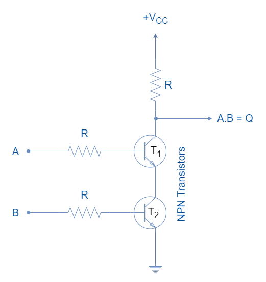
In the following figure, a basic two-input NAND gate constructed using Resistor-Transistor Logic (RTL) is shown.
Figure 2: The Resistor-Transistor Logic NAND Gate
When both inputs “A” and “B” are “HIGH” then both transistors are in saturated “ON” states and a state “LOW” appears at the output (Q). Turning any of the inputs to logic “LOW” will drive the relative transistor to the “OFF” state and pulls the output (Q) high to VCC.
Logic NAND Gate Symbol & Truth Tables
The representation of a NAND logic by a symbol is shown in the following figure. An inversion bubble at the output denotes the inversion of the multiplication.
Figure 3: Logic NAND Gate Symbol
The truth table of a two-input NAND logic gate is shown below:
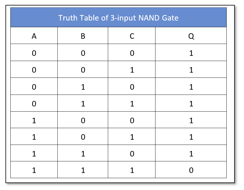
Similarly, the truth table of a three-input NAND logic gate is as follow:
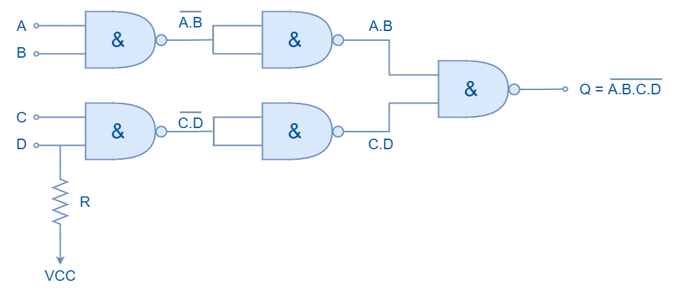
The Boolean expression can be extended to include multiple inputs to obtain a logic NAND operation. The commercially available NAND logic circuits have up to four inputs but the number of inputs can be further extended by cascading the NAND logic circuits. In the following figure, five two-inputs NAND gates are cascaded together to obtain a four-input NAND function.
Figure 4: A 4-input NAND logic constructed by cascading multiple NAND gates
The Boolean expression for this cascaded circuit can be written as:
Odd Number of Inputs
The NAND logic circuit having an odd number of inputs can be constructed by driving the unused input to logic “HIGH”. This will ensure that another input(s) of the NAND logic gate is truly reflected in the output. It is explained in the following diagram where unused input is pulled high using a pull-up resistor.
Figure 5: The NAND logic having an odd number of inputs
Universal Gate
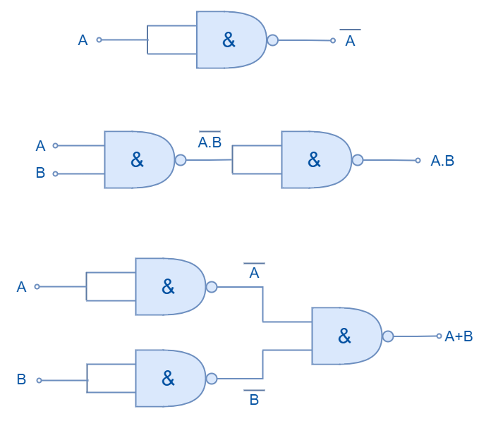
The logic NAND gate is described as a universal gate because it can be used to form the other logics i.e. AND, OR, NOT, Exclusive OR, Exclusive NOR, and NOR, etc. It is the most common and widely used logic gate because of its Universal Gating capability. The examples of forming the AND, OR, and NOT logic by using NAND gates are shown in the following figure.
Figure 6: Forming NOT, OR, and AND gates using NAND gates
Commercially Available NAND Gates
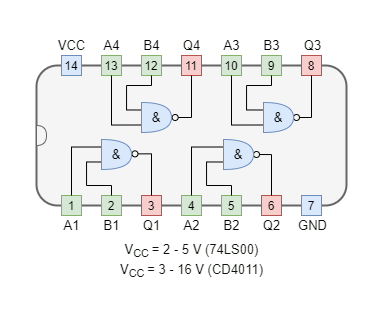
The NAND logic gates are available in both TTL and CMOS logic families. The most commonly used NAND logic packages are:
In the following figure, a NAND gate is used to drive a 12V relay to switch on the lamp using NI Multisim. The NAND gate (74LS00) turns off the relay when all of the inputs are connected to VCC. The relay thus turns off the lamp through an external circuit of 12V. When one of the inputs is connected to Ground, NAND logic goes “ON” turning the relay and lamp to “ON” state.
Figure 8: A Multisim circuit showing NAND logic to control an external circuit
Conclusion
The output of the NAND logic is “LOW” when all of the inputs are in logic “HIGH” states.
Any of the inputs in the logic “LOW” state will drive NAND logic to the “ON” state.
The NAND gate is sometimes referred to as Sheffer Stroke Function and is denoted by a bar between the inputs.
The NAND logic gates can be constructed using Resistor-Transistor Logic (RTL) but are seldom used because of the propagation delay and power consumption.
The NAND gate is termed a Universal Gate because of its capability to form any other logic using only NAND gates.
The NAND logic gates commercially available have up to eight NAND logic inputs. However, inputs can be extended by using cascaded NAND logic gates.
The NAND logic circuit having an odd number of inputs can be constructed by using a pull-up resistor on the unused pin.
An external circuit can be controlled by NAND logic with the use of a magnetic relay.
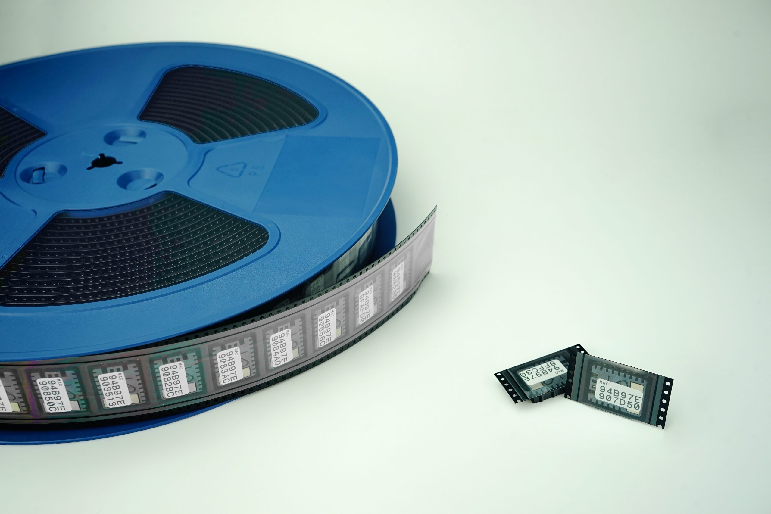
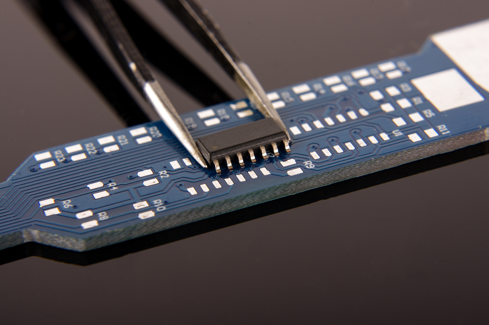
Surface Mount Technology was developed in the 1960s. During the 1970s and 1980s a revolution in the automation industry was begun, which raised the demand for Surface Mount Technology Components for a better assembly process. Before Surface Mount Technology, electronic components came with wire leads that were not ideal for complex devices. Moreover, such components with wire leads, now commonly known as through-hole components, were making the PCB assembly process significantly slow and costly. These problems were resolved by Surface Mount Technology (SMT), which has opened the door for the invention of complex electronics like mobile phones, laptops, medical products, industrial controls and sensors, and many more.
Surface Mounted Technology or “SMT” is used within the great majority of commercial electronics nowadays. The complex nature of SMT benefitted most applications of commercial electronics with the need to fit into very small spaces. To achieve this, components must be mounted directly onto the PCB surface as opposed to through-hole wire leads inserted into the board.
To say SMT was an important invention is an understatement. Electronic devices we have now would be much larger than they are. In fact, it’s safe to say that it’s a widely popular choice in today’s electronics. The reasons are many, including cost, size, simplicity of assembly and the amount of functionality demanded within a small volume. It’s these vital advantages that have seen SMT devices dominate the market. Here’s a rundown of some of the advantages afforded to surface-mounted technology devices.
Advantages of Surface Mounted Technology
SMT allows for automated production and soldering and makes the whole process quick and simple. This results in considerable savings in time and money and allows for a lot more consistency in output..
Fewer holes are required to be drilled into circuit boards; consequently, this makes the PCB more robust and cheaper.
Costs of SM components are much lower than through-hole components.
Both sides of the circuit board can have SMT parts on them, offering much more usable space. Moreover, SMT components are much smaller, which in turn saves valuable, maybe crucial space.
SMT components offer much better performance under vibration and dropping or shaking, as they are much lighter in weight; The SMT component can weigh as little as one-tenth of their common through-hole equivalents.
Unlike through-hole components, small errors in the placement of components are corrected automatically since the surface tension of molten solder pulls SMT components into alignment with solder pads. A well-designed PCB will optimize this.
PCBs made from SMT components generally have lower resistance and inductance. This can be crucial for better high-frequency performance and to filter out unwanted RF signal effects.
SMT components offer a smaller radiation loop area, hence provide better EMC (Electromagnetic Compatibility) performance.
As with everything in life, while something may have its advantages, it will usually have a few disadvantages too. These include:
High power output or physically large parts aren’t suitable. You must use through-hole construction for that and other design requirements.
Manual repair of surface-mounted technology can be tricky due to the significantly smaller size of SMT component joints. You will need well-trained operators and sophisticated equipment in order to carry out efficient repair and rework.
SMT component joints can be less physically robust than through-hole components. This is due to the physically smaller joints with less solder. The void formation can easily be missed during inspection of the assembly due to the smaller dimensions, contributing towards poor thermal and mechanical performance. Skillful design and layout of the PCB can help mitigate this.
Surface Mounted Technology isn’t suitable for components that endure frequent connecting and subsequent disconnecting. The mechanical strain on unsupported SMT components has a far worse effect than it does with through-hole components (which are by default, anchored into the PCB)
SMT components are not suitable for applications that require the whole design to be sturdier against external forces. Through-hole technology provides more protection against environmental stress, and it has retained more application in the military and aerospace industry because of this.
Scope of Application:
To conclude, SMT components are ideal when it comes to applications that are sensitive to processor speed, where resistance and inductance of circuits are important ( for example RF communication and high-speed digital processing). For high-frequency applications, these are pivotal advantages over rather insignificant disadvantages. In higher current or harsh vibration environments, the advantages of SMT are outweighed by the vulnerability, and through-hole technology would be better. You, therefore, need to use your expertise while considering the pros and cons of Surface Mount Components with their through-hole counterparts for each application. It is also vital not to overlook the optimization of your PCB design while making your ideal selection.
Contact Advanced Rework Technology Today
Training is available to help comply with best practices in the design and assembly of SMT products. We recommend that your designers are qualified for to “Advanced Certified Interconnect Designer (CID+)” status. We recommend that your production staff are trained and regularly re-certified for some of the several IPC courses applicable to the circuit board and cable harness production. This will ensure consistent output quality and less rework, thereby reducing costs and lowering product reject rates in service. Ask us for a free consultation on how we can help. Contact A.R.T today or give us a call and speak to one of our team on 01245 237 083.