This precision thermocouple sensor module performs cold-junction compensation and digitizes the signal from any type of thermocouple. The output data is formatted in degrees Celsius. The converter resolves temperatures to 0.0078125°C, allows readings as high as +1800°C and as low as -210°C (depending on thermocouple type), and exhibits thermocouple voltage measurement accuracy of ±0.15%. The thermocouple inputs are protected against overvoltage conditions up to ±45V. A lookup table (LUT) stores linearity correction data for several types of thermocouples (K, J, N, R, S, T, E, and B). Line frequency filtering of 50Hz and 60Hz is included, as well as thermocouple fault detection. An SPI-compatible interface allows the selection of thermocouple type and setup of the conversion and fault detection processes. The operating supply of the project is 5V and it consumes a very low current. The module communicates over the SPI interface.
Arduino Interface
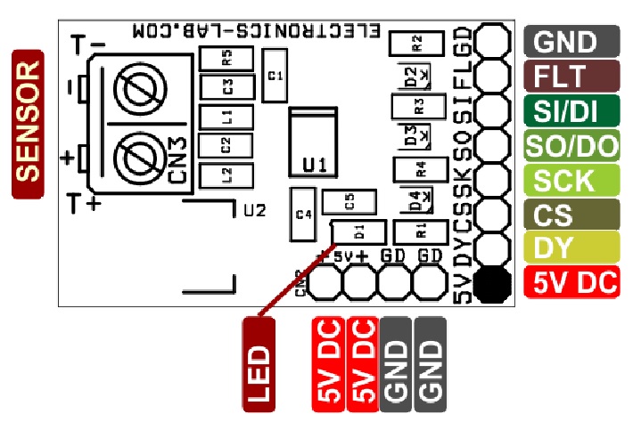
Testing this module with Arduino is very easy. The pin configuration information is available below.
Adafruit library and example code are available at the Adafruit website below and on downloads under the article.
Arduino Connection to board CN1
- CN1 Pin 1 >> 5V
- CN1 Pin 2 >> DY DIGITAL PIN D5
- CN1 Pin 3 >> CS DIGITAL PIN D10
- CN1 Pin 4 >> SK DIGITAL PIN D13
- CN1 Pin 5 >> SO DIGITAL PIN D12
- CN1 Pin 6 >> SI DIGITAL PIN D11
- CN1 Pin 7 >> FAULT NO CONNECTION
- CN1 Pin 8 >> GND
Features
- Supply 5V DC @ 10mA
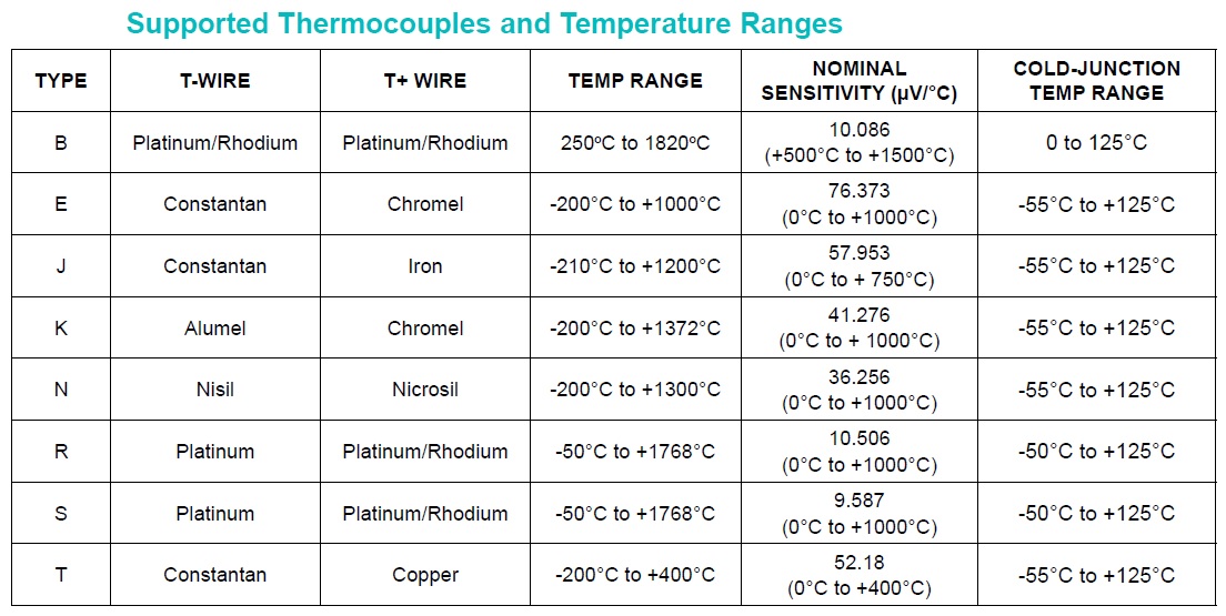
- Supports K, J, N, R, S, T, E, and B Type Thermocouples
- Easy SPI Interface
- Screw Terminal for Easy Sensor Connections
- Male Header Connector for Micro-Controller Connections
- On-Board Power LED
- Detects Open Thermocouples
- Over- and Under temperature Fault Detection
- Provides High-Accuracy Thermocouple Temperature Readings
- Includes Automatic Linearization Correction for 8 Thermocouple Types
- ±0.15% (max, -20°C to +85°C) Thermocouple Full- Scale and Linearity Error
- 19-Bit, 0.0078125°C Thermocouple Temperature Resolution
- Internal Cold-Junction Compensation Minimizes System Components
- ±0.7°C (max, -20°C to +85°C) Cold-Junction Accuracy
- ±45V Input Protection Provides Robust System Performance
- Simplifies System Fault Management and Troubleshooting
- 50Hz/60Hz Noise Rejection Filtering Improves System Performance
- PCB dimensions: 21.59 x 33.81 mm
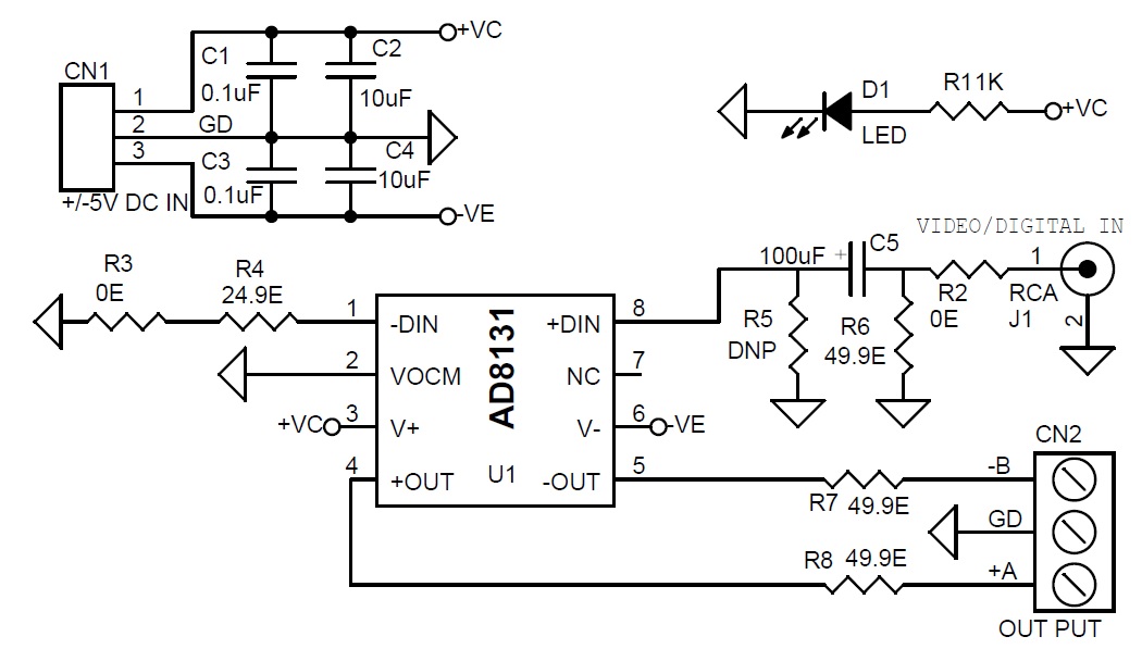
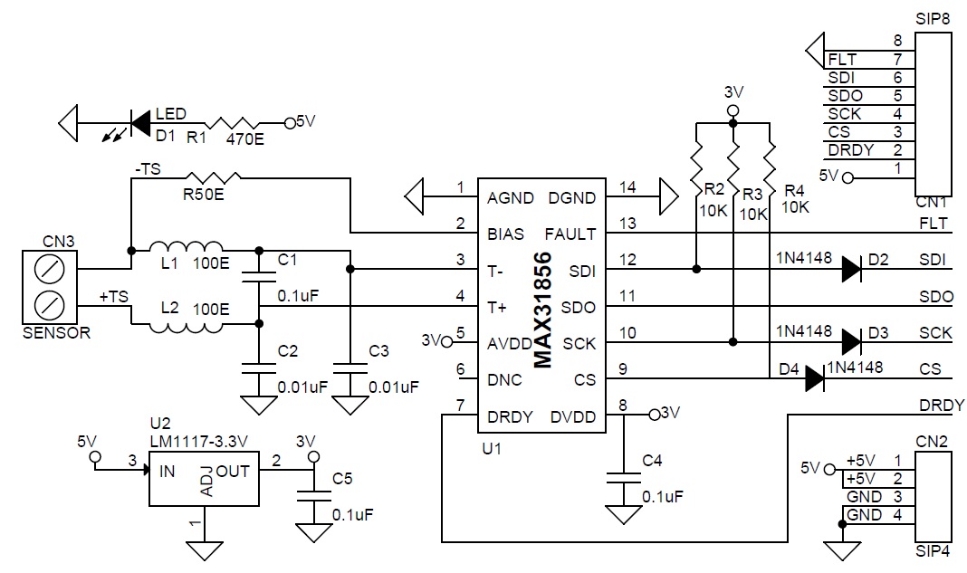
Schematic
Parts List
| NO. | QNTY. | REF. | DESC. | MANUFACTURER | SUPPLIER | SUPPLIER PART NO |
|---|---|---|---|---|---|---|
| 1 | 1 | CN1 | 8 PIN MALE HEADER PITCH 2.54MM | WURTH | DIGIKEY | 732-5321-ND |
| 2 | 1 | CN2 | 4 PIN MALE HEADER PITCH 2.54MM | DNP | DNP | |
| 3 | 1 | CN3 | 2 PIN SCREW TERMINAL PITCH 5.08MM | PHOENIX | DIGIKEY | 277-1247-ND |
| 4 | 3 | C1,C4,C5 | 0.1uF/50V SMD SIZE 0805 | MURATA/YAGEO | DIGIKEY | |
| 5 | 2 | C2,C3 | 0.01uF/50V SMD SIZE 0805 | MURATA/YAGEO | DIGIKEY | |
| 6 | 1 | D1 | LED SMD SIZE 0805 | OSRAM | DIGIKEY | 475-1278-1-ND |
| 7 | 3 | D2,D3,D4 | 1N4148 SMD | MICROCHIP | DIGIKEY | 1N4148UR-1-ND |
| 8 | 2 | L1,L2 | FERRITE BEAD OR 100E 5% RESISTOR SMD SIZE 0805 | MURATA/YAGEO | DIGIKEY | |
| 9 | 1 | R1 | 470E 5% SMD SIZE 0805 | MURATA/YAGEO | DIGIKEY | |
| 10 | 3 | R2,R3,R4 | 10K 5% SMD SIZE 0805 | MURATA/YAGEO | DIGIKEY | |
| 11 | 1 | R5 | 0E SMD SIZE 0805 | MURATA/YAGEO | DIGIKEY | |
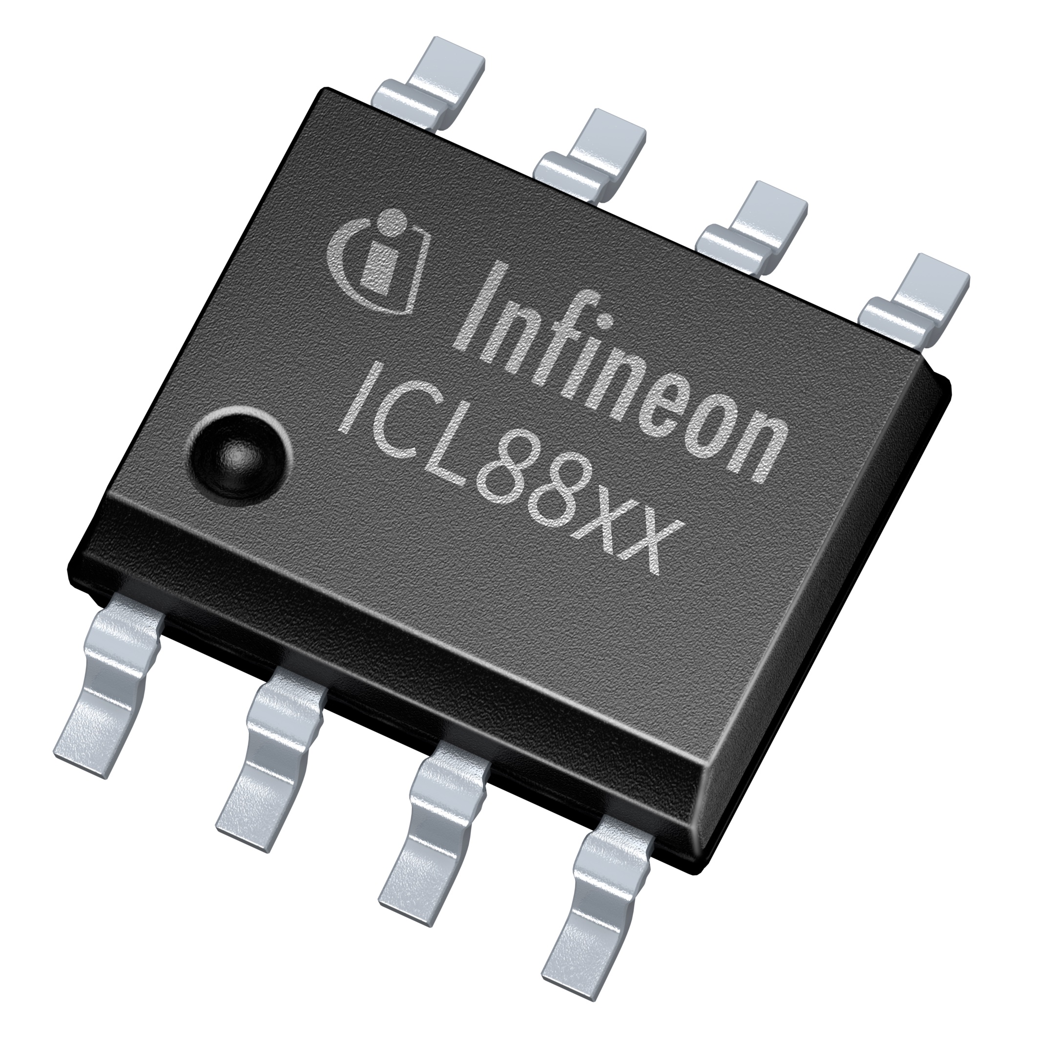
| 12 | 1 | U1 | MAX31856 | MAXIM | DIGIKEY | MAX31856MUD+-ND |
| 13 | 1 | U2 | LM117-3.3V | TI | DIGIKEY | LM1117MP-3.3/NOPBCT-ND |
Connections
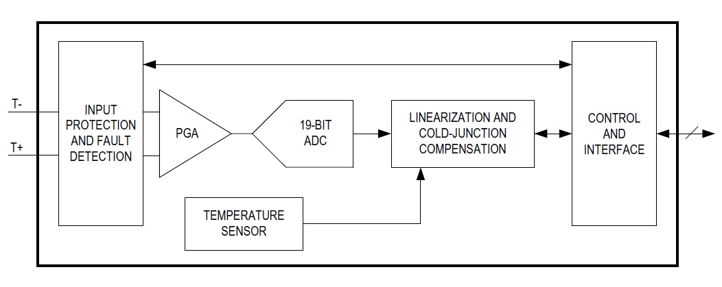
Block Diagram
Supported Thermocouple Types
Gerber View
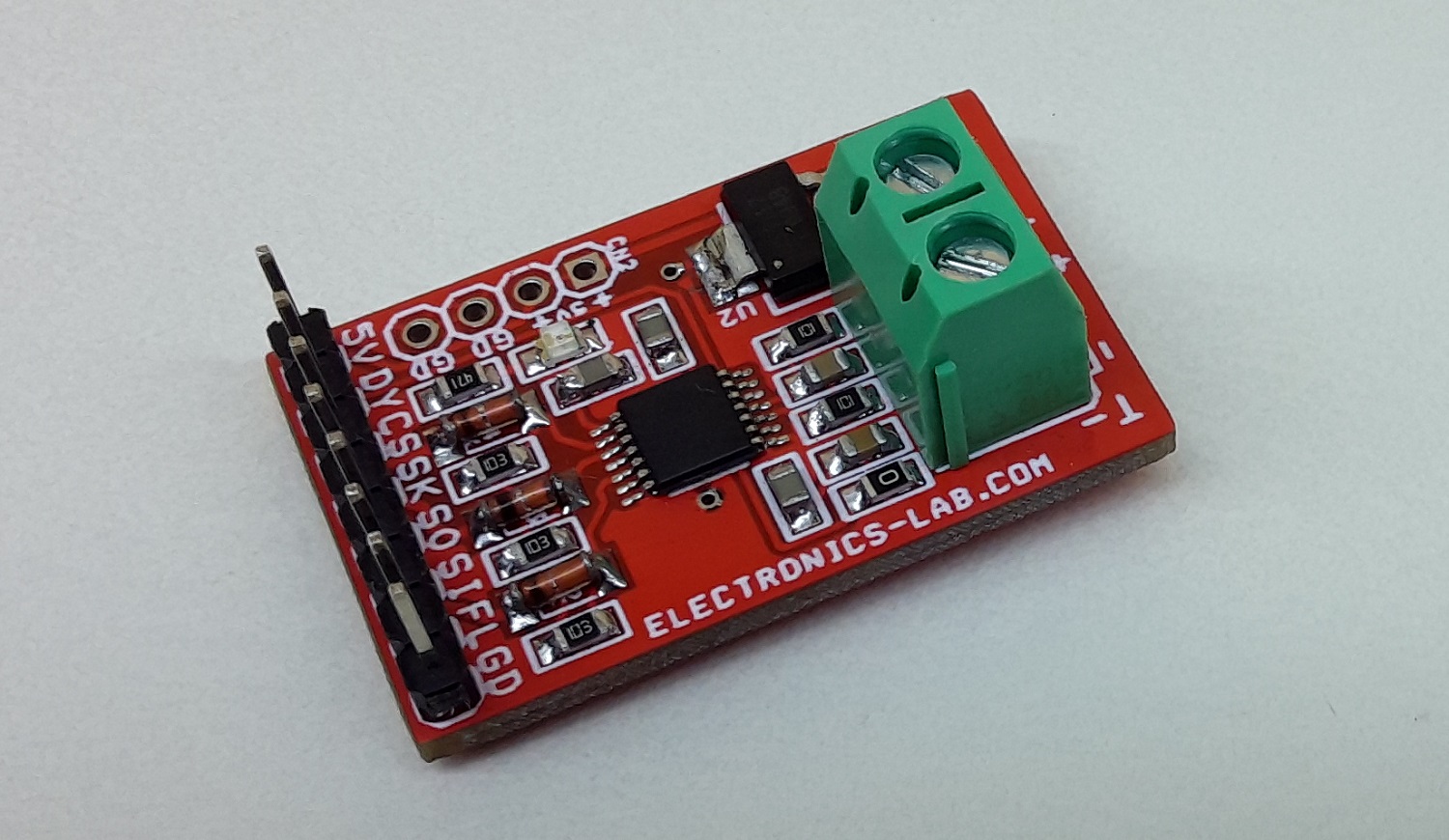
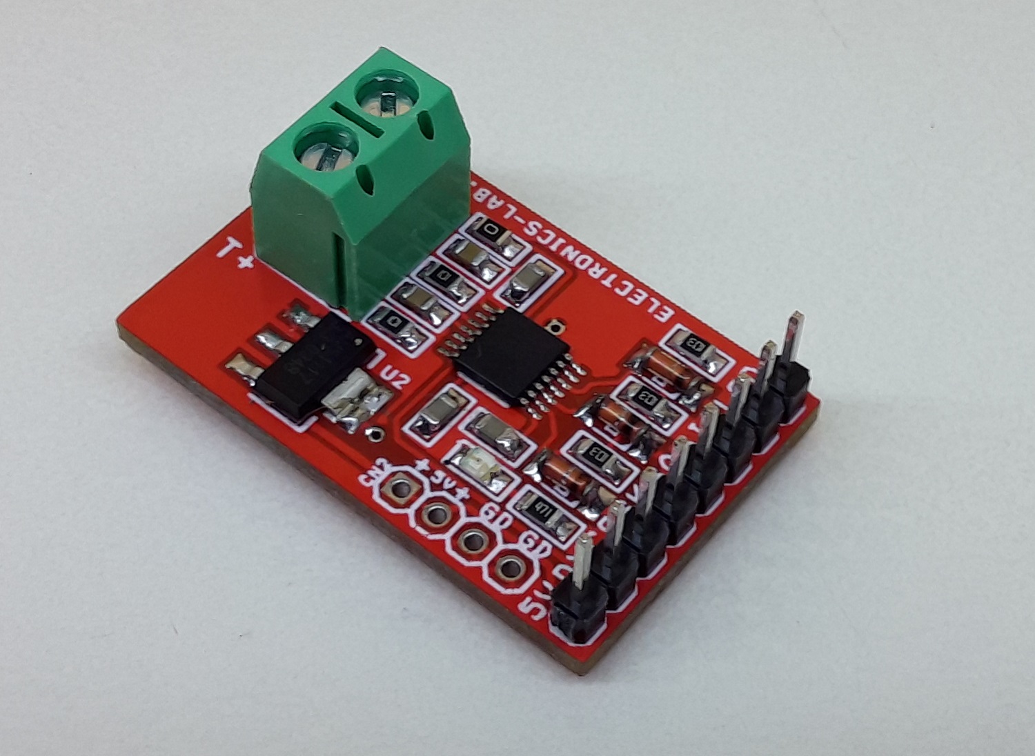
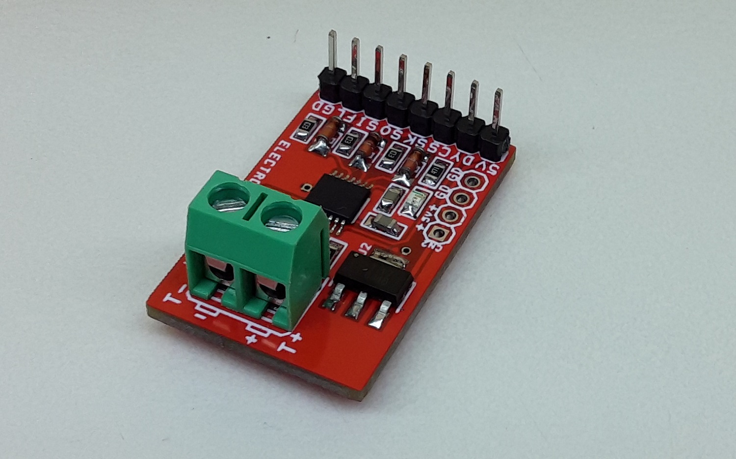
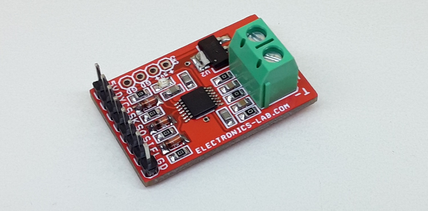
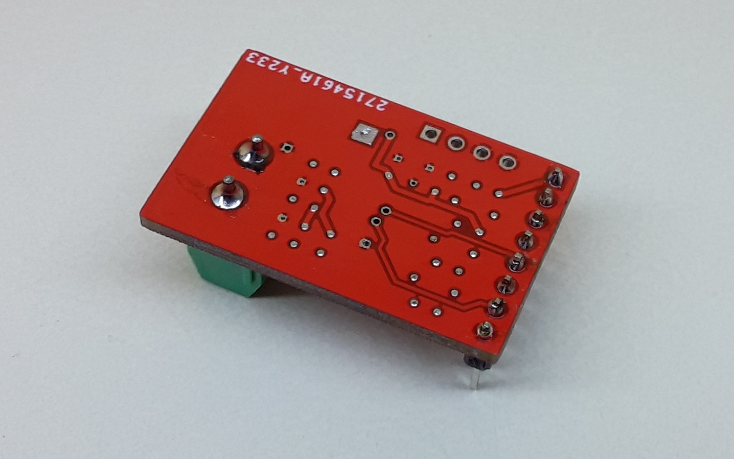
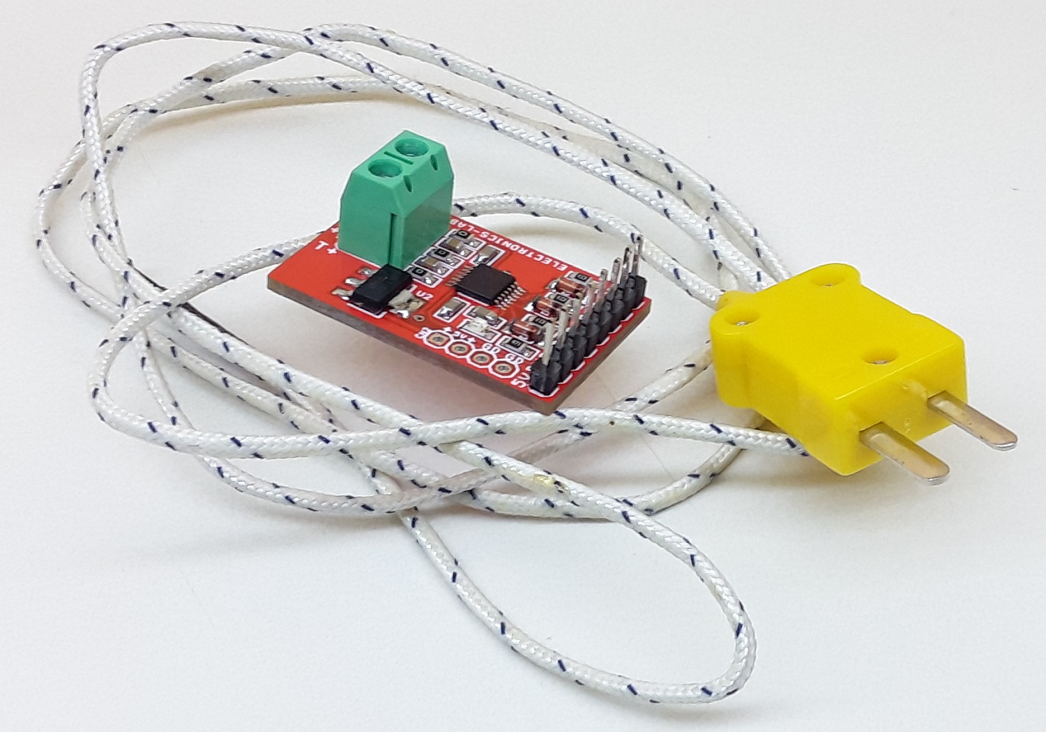
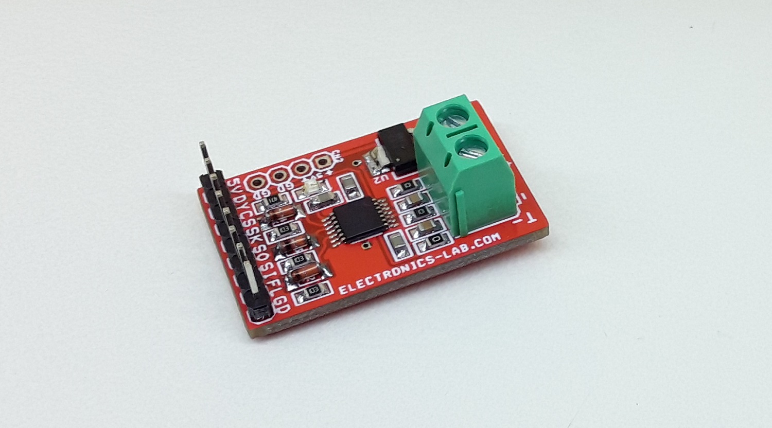
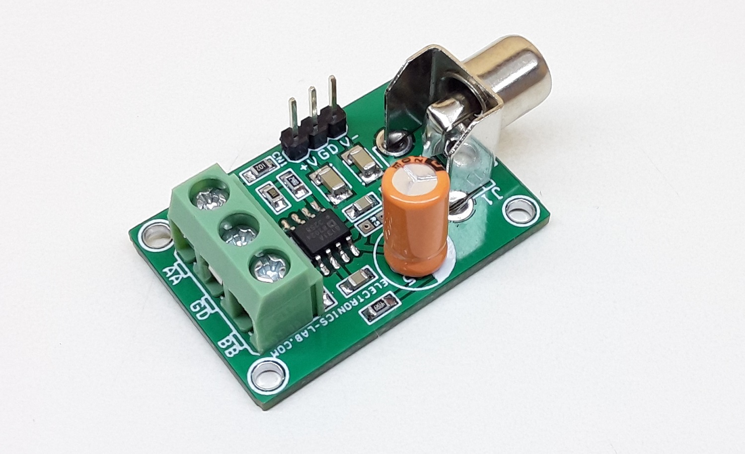
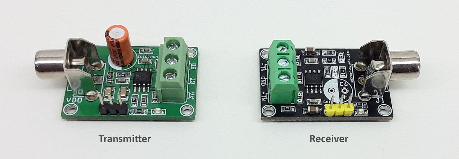
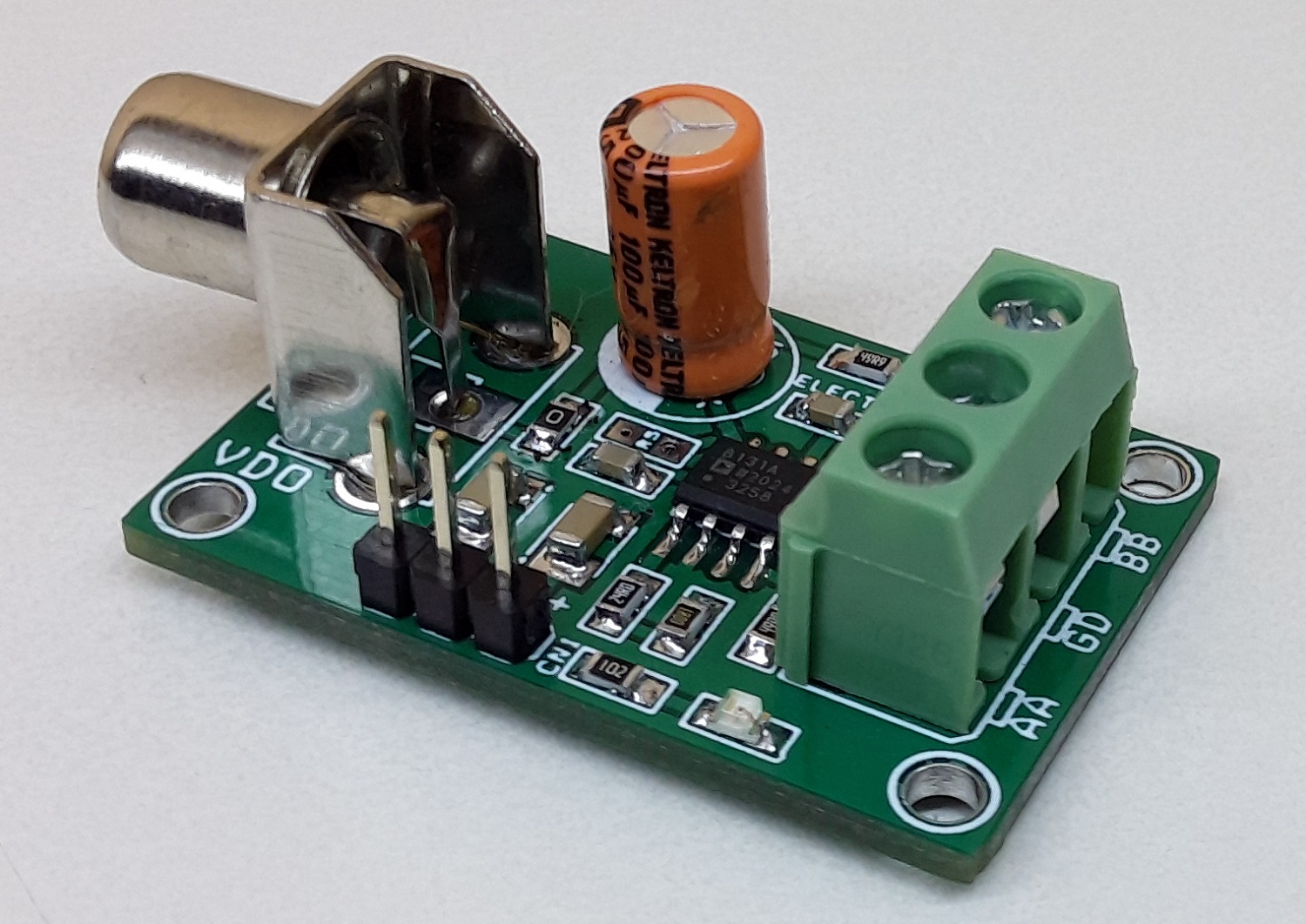
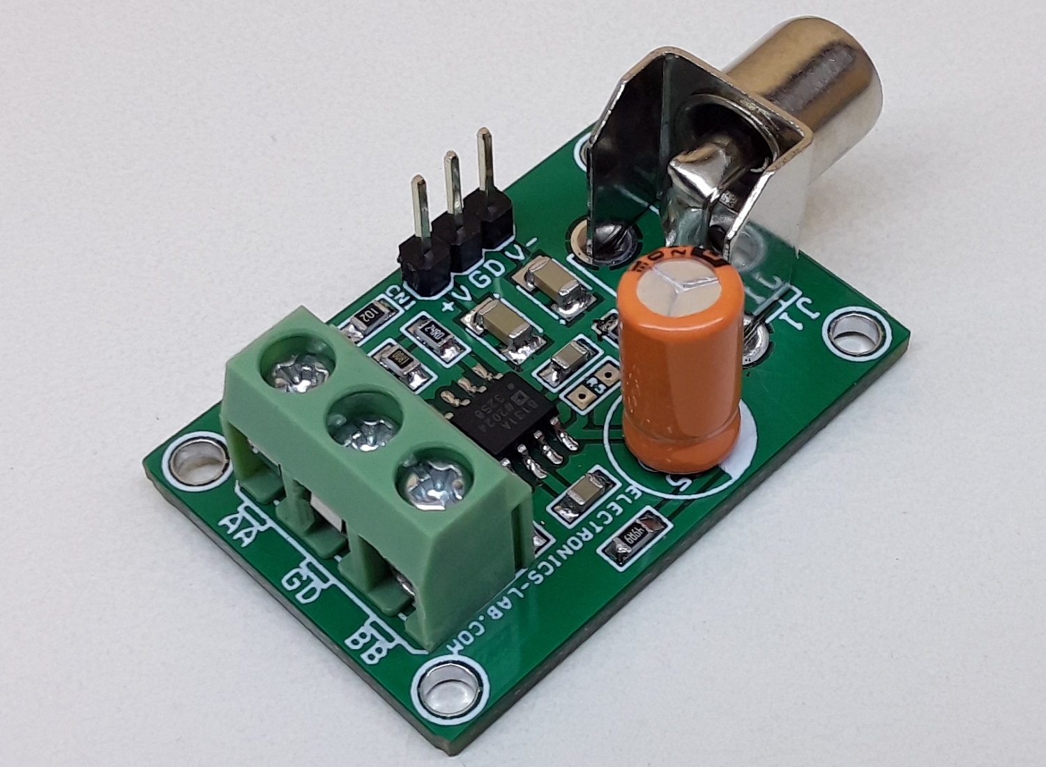
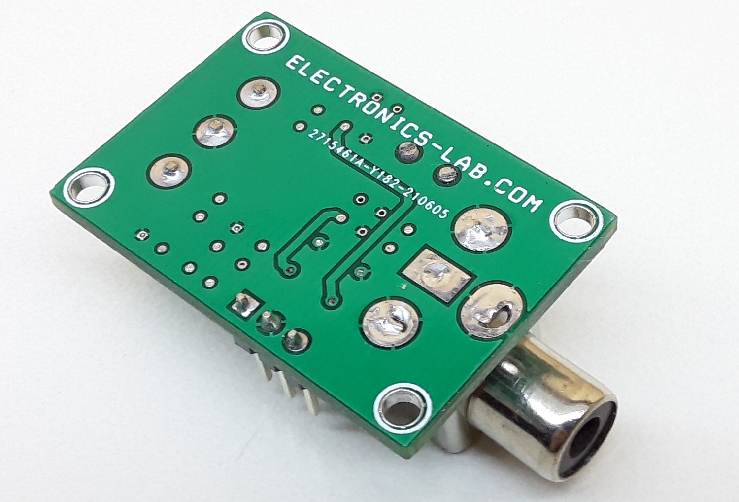
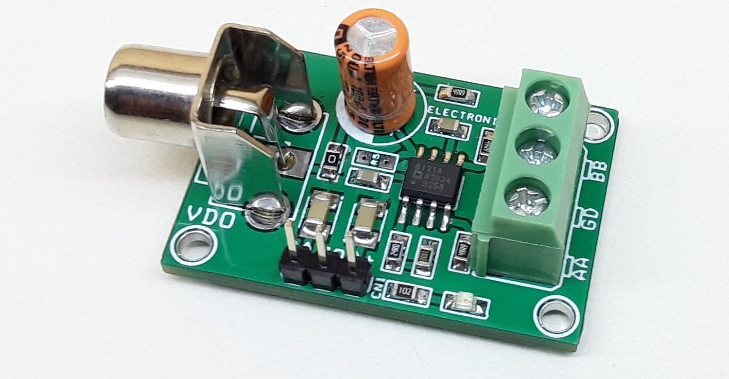
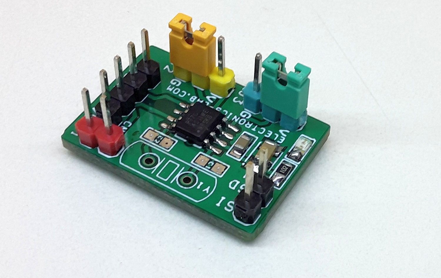
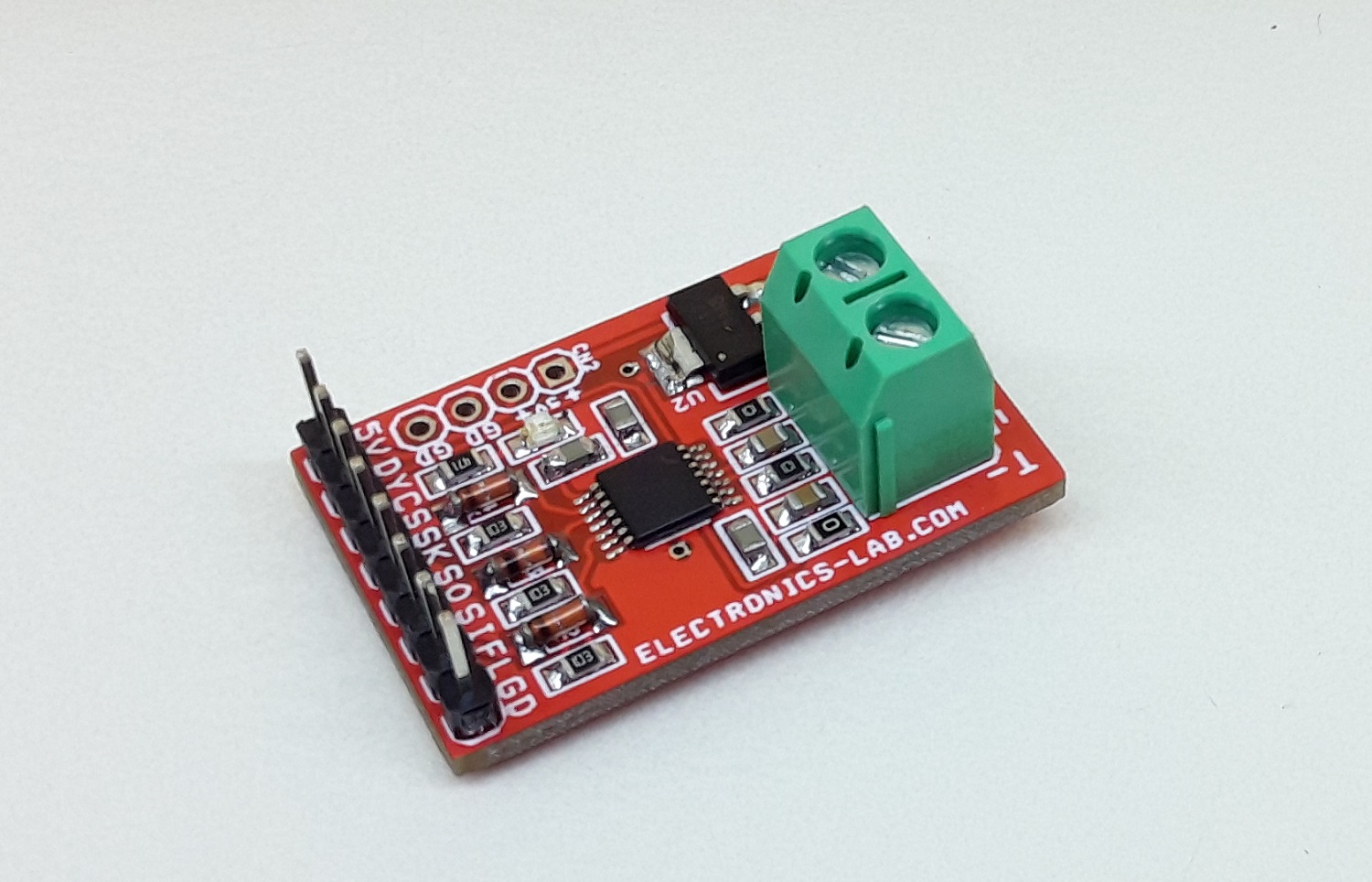
Photos