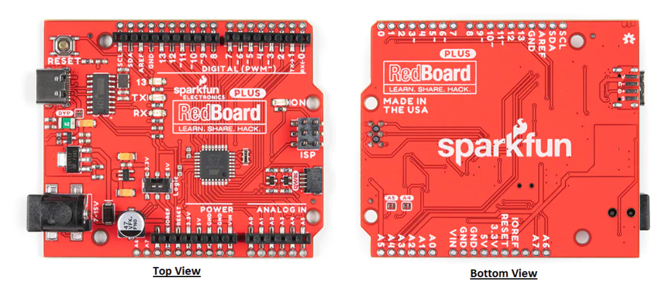
SparkFun RedBoard Plus Development Board is an Arduino-compatible board that is similar to an Arduino Uno with many extra perks. This DEV-1858 development board utilizes a handy Qwiic Connect System that means no soldering or shields are required to connect it to the rest of the system. The RedBoard Plus board includes the hardware peripherals like 22x digital I/O pins with 6x PWM pins, 8x analog pins, UART, I2C, SPI, and external interrupts. This board uses the LM1117 5V voltage regulator and AP2112 3.3V voltage regulator that provides up to 600mA to daisy chain multiple Qwiic boards and sensors. The RedBoard Plus board comes with an I/O voltage switch also known as the “Red Squirrel” switch. This Red Squirrel switch can easily select the GPIO voltage between 3.3V to 5V.
The RedBoard Plus can be programmed over a USB-C cable with 5V input voltage or through the barrel jack from 7V to 15V input voltage. This development board features 32kB flash memory, 16MHz clock speed, all SMD construction, R3 shield compatibility, and an improved reset button.
Features
ATmega328P MCU with Optiboot (UNO) bootloader
Input voltage:
7V to 15V via barrel jack
5V via USB-C
Voltage regulators:
LM1117 adjusted to 5V
AP2112 for 3.3V
Built-in resettable PTC fuse 5V/2A
CH340G Serial-to-USB converter
3.3V to 5V logic level switch
22x digital I/O pins:
6x PWM outputs, 8x analog inputs, UART, I2C, and SPI
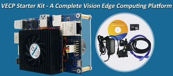
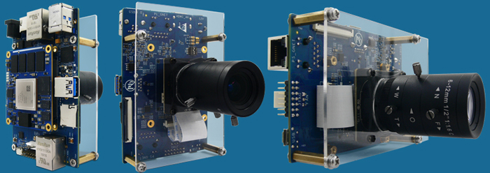
MYIR introduces the VECP Starter Kit, a complete Vision Edge Computing Platform designed to support excellent image processing for typical applications like Machine Vision, Industry, IoT, Medical and more others in different areas of business and everyday life.
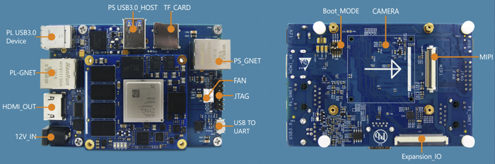
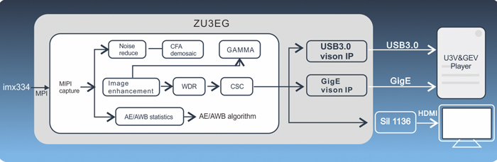
The VECP Starter Kit is using Xilinx Zynq UltraScale+ ZU3EG solution and comes with a MYD-CZU3EG-ISP development board as well as some accessories to help users start their development rapidly. The MYD-CZU3EG-ISP board consists of a MYC-CZU3EG CPU Module with installed active heatsink, a base board and a SONY imx334 4K Sensor which is installed on the rear of the base board and connected to the board MIPI-CSI interface through an FPC cable. The board is ready to run Linux OS and provided with plenty of software resources.
The MYD-CZU3EG-ISP development board shows outstanding image processing performance through the built-in ISP core which is capable of handling 4K video at 30fps and implementing ultra-low delay video transmission at maximum 0.7ms. It also has integrated IP cores for high-speed video standards like GigE Vision and USB3 vision to allow the image transmission via the Gigabit Ethernet or USB 3.0 from the board FPGA logic part.
The VECP Starter Kit is offered at $599/unit only. MYIR also offers custom design services for board design based on the MYD-CZU3EG-ISP development board or customized image sensors or customized IP cores according to customers’ requirements.
For whatever deep learning purpose or production, the VECP Starter Kit will be easy for users to begin their edging computing experience and reduce their time to market with the design reference or system integration.
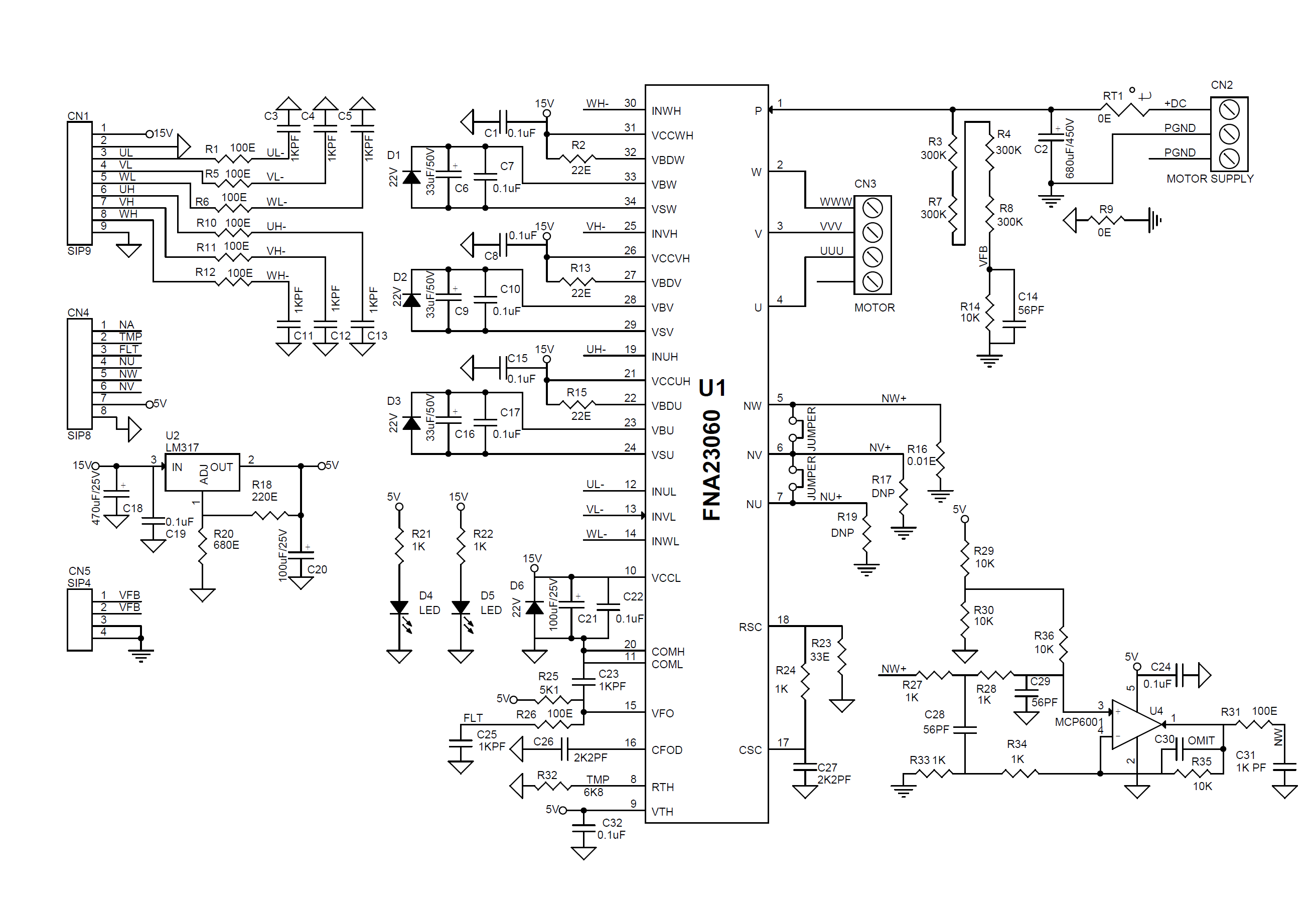
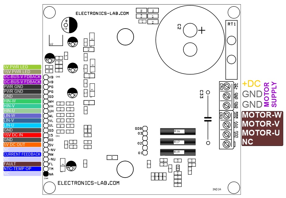
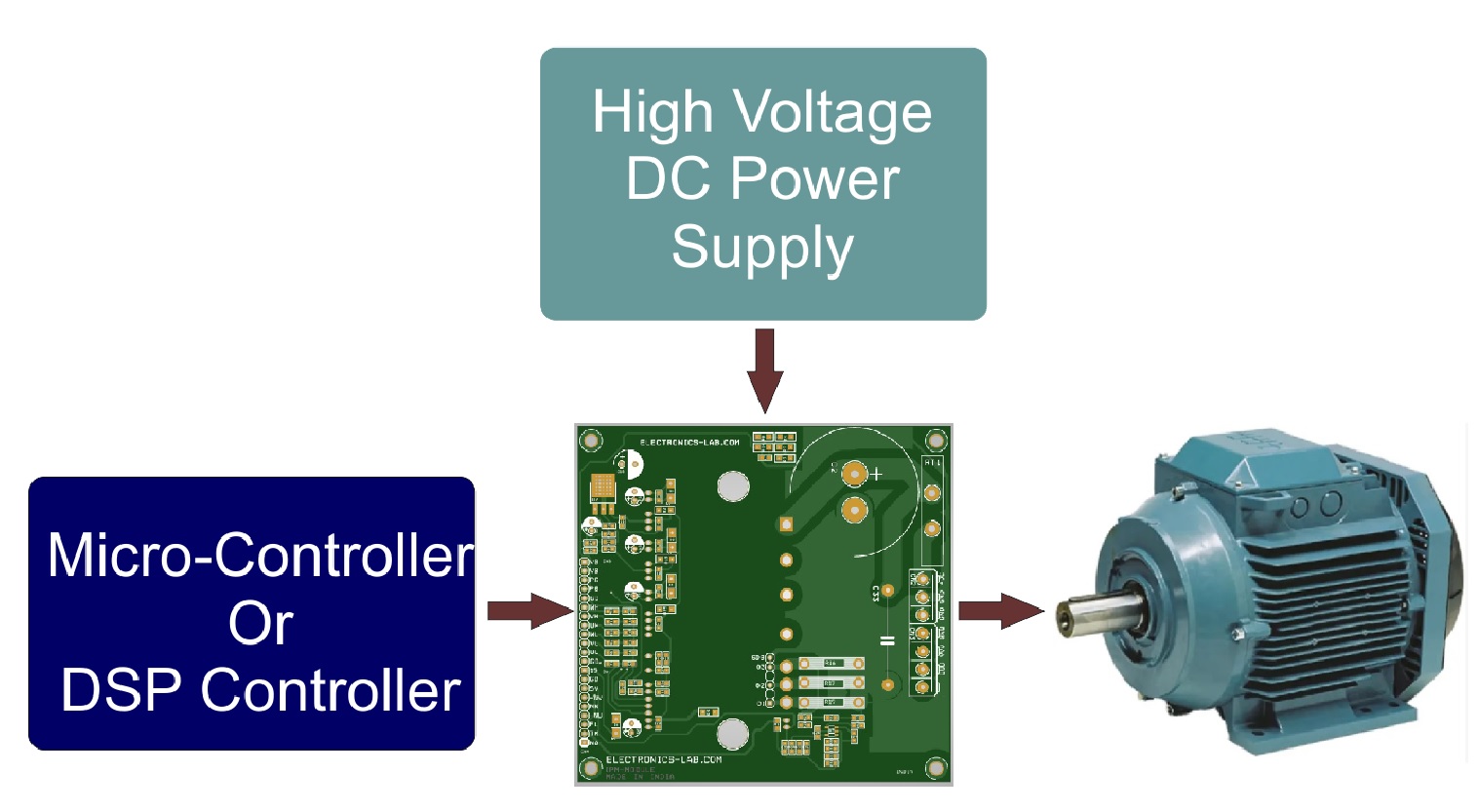
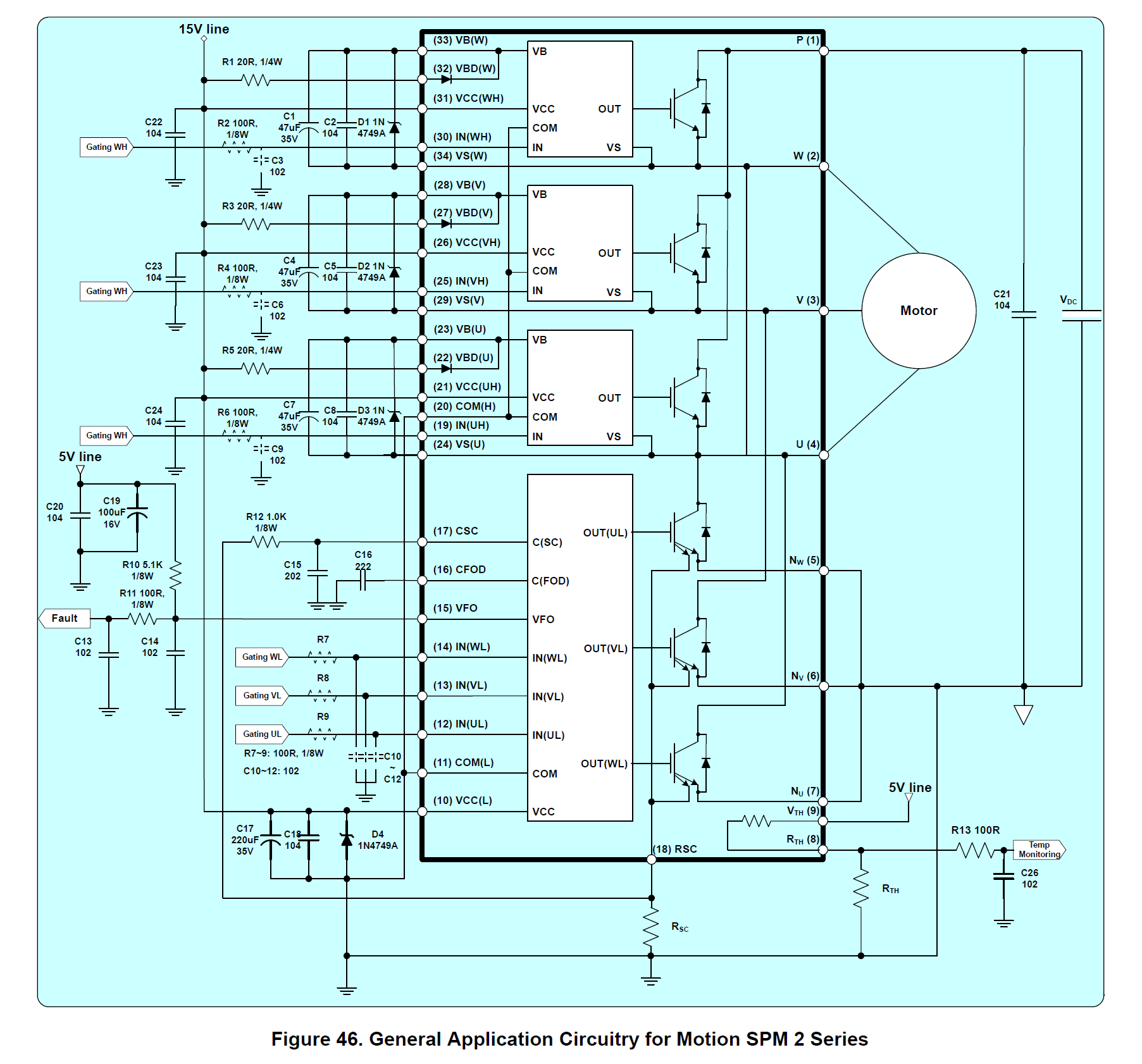
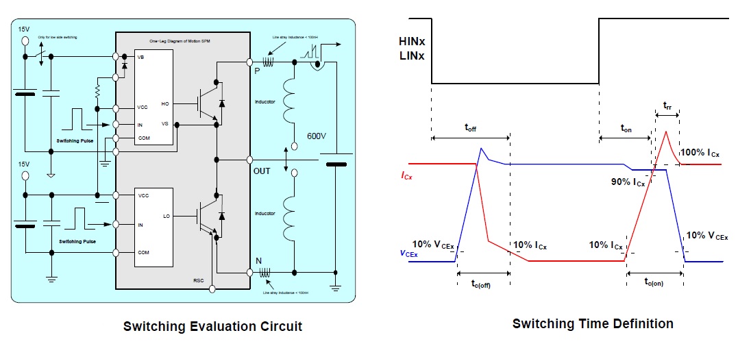
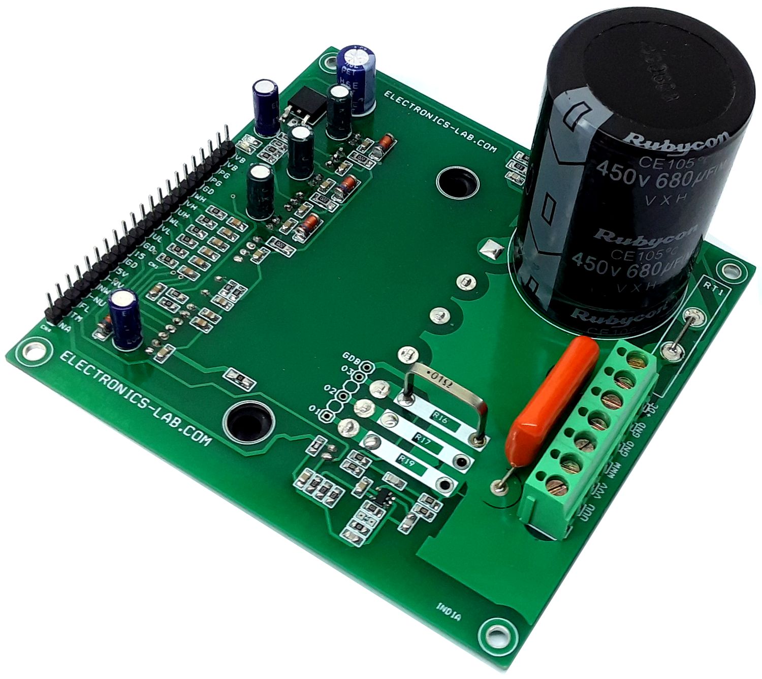
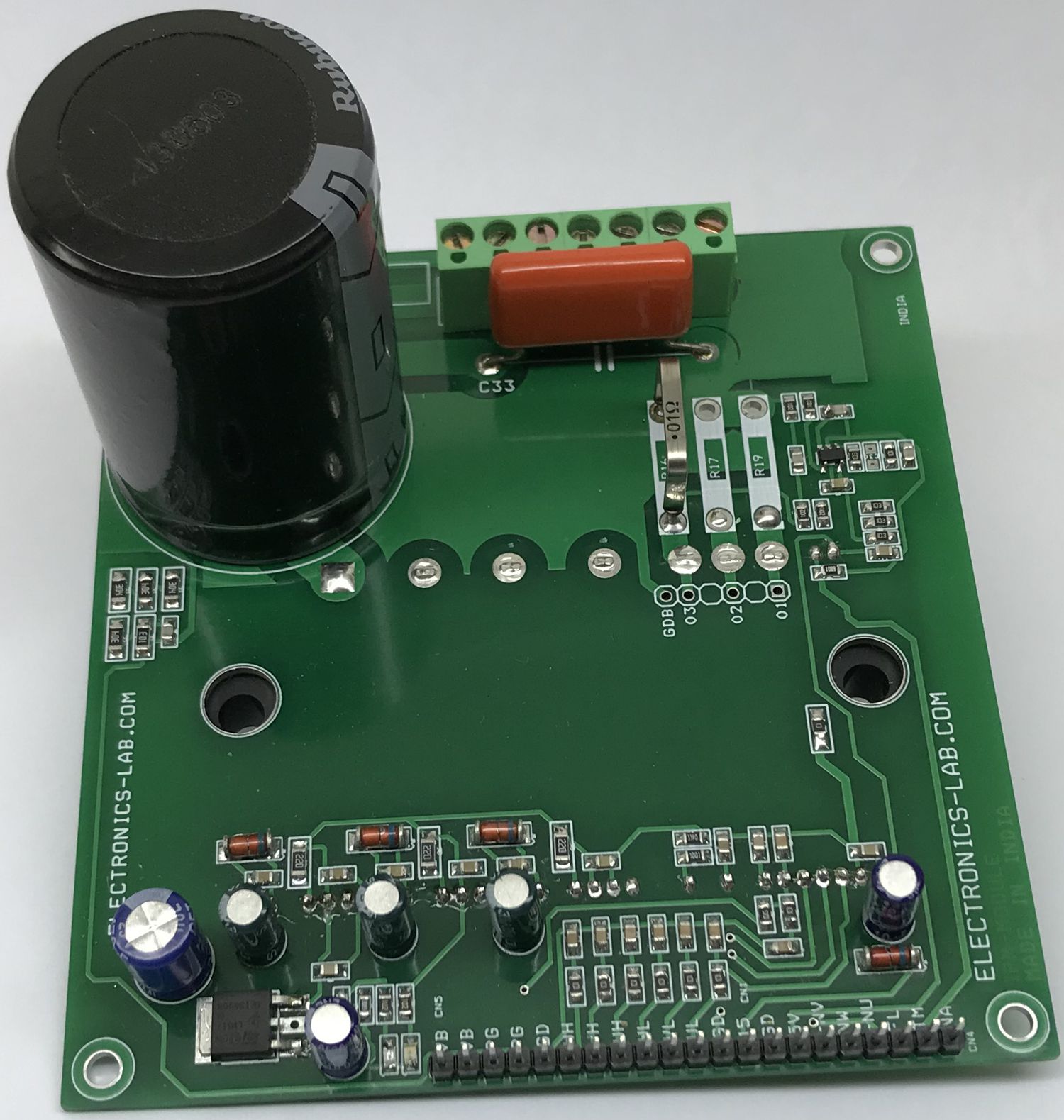
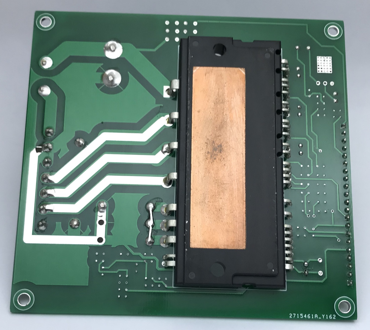
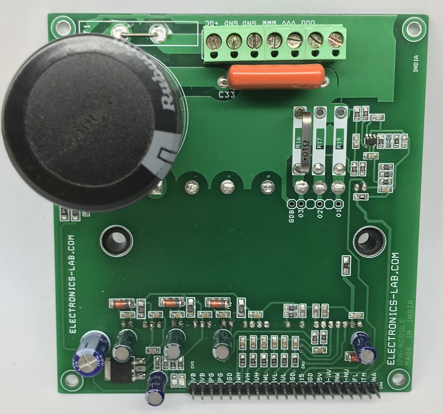
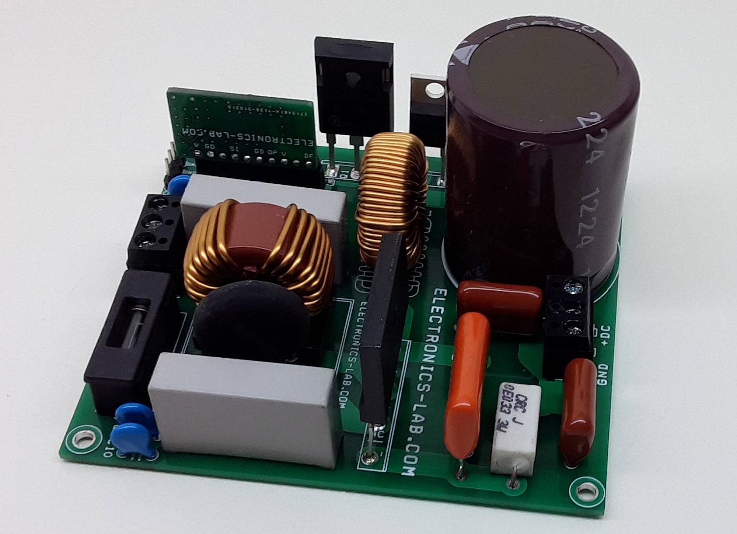
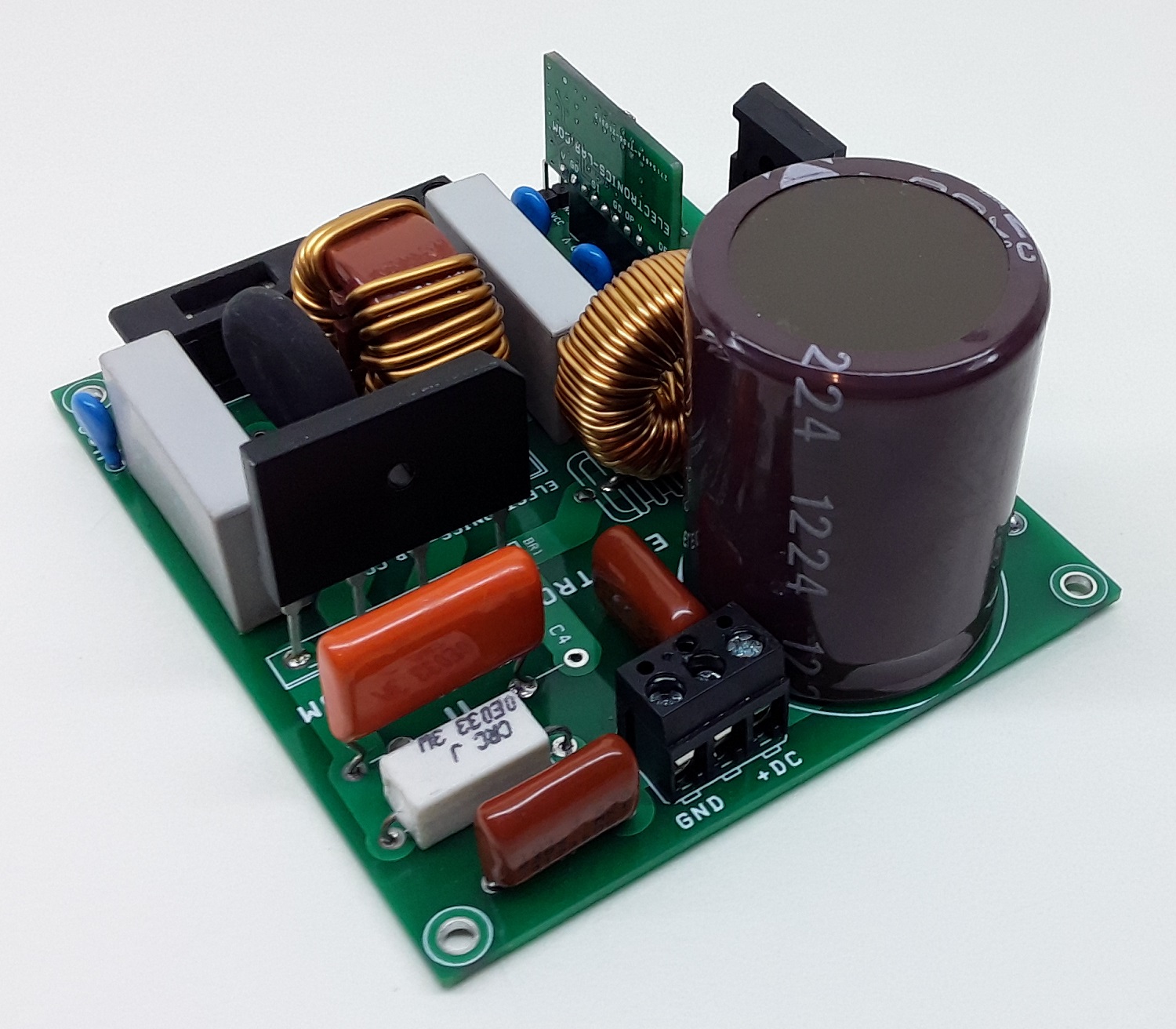
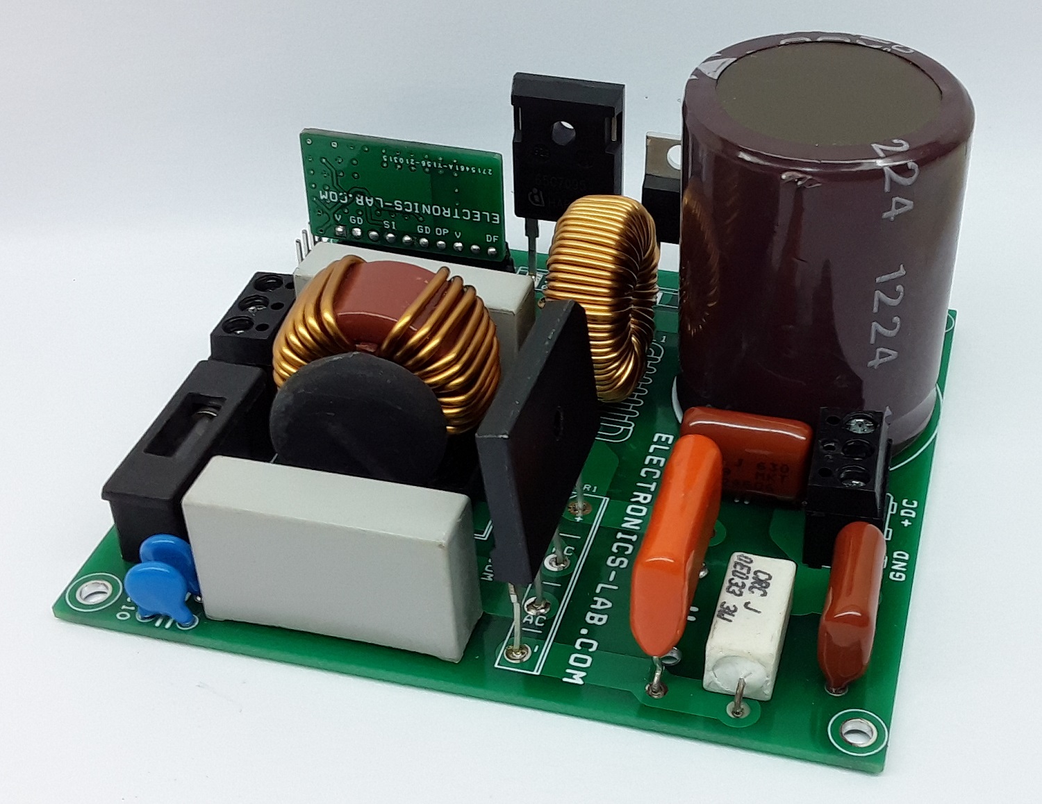
This compact IPM module circuit provides a fully-featured, high-performance inverter output stage for AC Induction, BLDC, and PMSM motors. The circuit is based on FNA23060 chip which integrates the optimized gate drive of the built-in IGBTs to minimize EMI and losses, while also providing multiple on-module protection features: under-voltage lockouts, over-current shutdown, temperature sensing, and fault reporting. The built-in, high-speed HVIC requires only a single supply of 15V and translates the incoming logic-level gate inputs to high-voltage, high-current drive signals to properly drive the module’s internal IGBTs. On-Board optional current sense circuit can be used to monitor the current. LM317 regulator provides 5V DC output to drive op-amp current sense circuit. LED D4 and D5 indicate 5V power and 15V power. Board has an option for 3 current sense resistors. An external 3 phase current circuit is required for 3 phase current sense circuit, if a single current sense circuit is required, solder all 3 phase NU+, NV+, NW+ together and use U4 op-amp circuit, in this case, solder R16. The current sense circuit is built using op-amp based, the gain of the circuit can be set as per user requirement. The board works with lethal high voltage DC and requires extra care while testing. PFC-based DC power supply is recommended to power the board.
Note: It is advisable to read the datasheet of FNA23060 to configure and control this board, current trip, Fault output, input PWM sequence, Over temperature output.
The board operates at lethal voltages and has bulk capacitors that store significant charge. Accidental contact can lead to lab equipment damage, personnel injury, and may be fatal. Please be exceptionally careful when probing and handling this board. Always observe normal laboratory precautions.
Features
Operating Supply Motor 90V to 390V DC
IPM Load Current Maximum 30Amps (Approx. 2.2KW Motor Rating)
Logic Supply 15V DC
Motor Supply (Bus-Voltage Feed-Back Output 3.2V when Bus 390V, 0.75 when Bus V=90V)
On-Board Current Sense Circuit
Current Sense Output 1.7V at 0 Amp 100mV/Amp Approx.
2X Power LEDs for 15V and 5V
Fault Output Normally High Goes Low When Fault Condition Occurs
Inbuilt Thermistor for over Temperature 47K Ohms @ 25 Degree Centigrade, 2.9K @ 100 Degree Centigrade
Over Temperature Protection Output
Operating Frequency up to 20Khz
PCB Dimensions 100.17 x 104.93 mm
Current Sense: the board has provision to mount 3 shunt resistors if 3 phase current monitor is required, in this case, use R16, R17, R19 resistors. This will require 3 phase current to voltage op-amp circuit, the board has provision to measure a single current sense, in this case, solder all 3 emitters of IGBTs (Pin 5,6,7) and use U4 op-amp circuit to monitor the current of the motor.
Over Current: The IPM module has an inbuilt separate over-current shutdown circuit, over-current is set using R23, R24, and C27, refer to datasheet of IC to calculate the Over Current shutdown threshold as per requirement.
Signal Input Pins: Pins IN(UL), IN(VL), IN(WL), IN(UH), IN(VH), IN(WH), These pins control the operation of the built−in IGBTs. They are activated by voltage input signals. The terminals are internally connected to a Schmitt−trigger circuit composed of 5 V−class CMOS. The signal logic of these pins is active HIGH. The IGBT associated with each of these pins is turned ON when a sufficient logic voltage is applied to these pins. The wiring of each input should be as short as possible to protect the Motion against noise influences. To prevent signal oscillations, RC (Resistors and capacitors) R1, R5, R6, R11, R12, R13, C3, C4, C5, C11, C12, C13) provided at all 6 inputs signals.
Power Supply: 15V DC supply required to drive the Logic gate driver circuit Use Pin 1and 2 of connector CN1 to apply logic supply. U2 LM317 regulator provides 5V DC to op-amp circuit for current sense. CN2 screw terminals are provided to power the load.
Power LED: D4 5V LED, D5 15V LED
Motor Supply Voltage Feedback: CN5 Connector provides Bus voltage (Motor Supply) feedback (Output 3.2V when 390V, 0.75V when Bus V=90V)
Motor Connections: 4 Pin screw terminal CN3 for motor connections, pin 1 motor phase W, pin 2 motor phase V, pin 3 motor phase U
Heatsink: Large size heatsink and fan is very important to cool down the IPM module.
Arduino Connections and Code
We tested the board with Arduino UNO board and ARDUINO_UNO_Code.zip. Please follow the instructions below to connect Arduino with the IPM board.
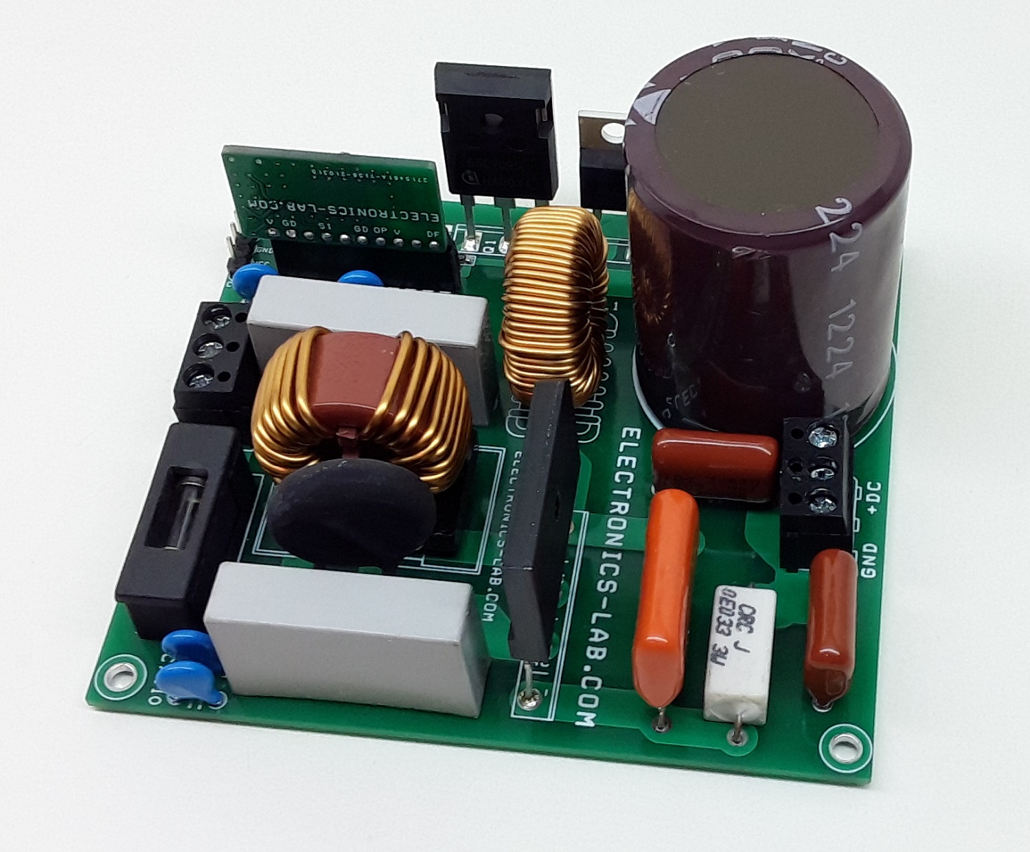
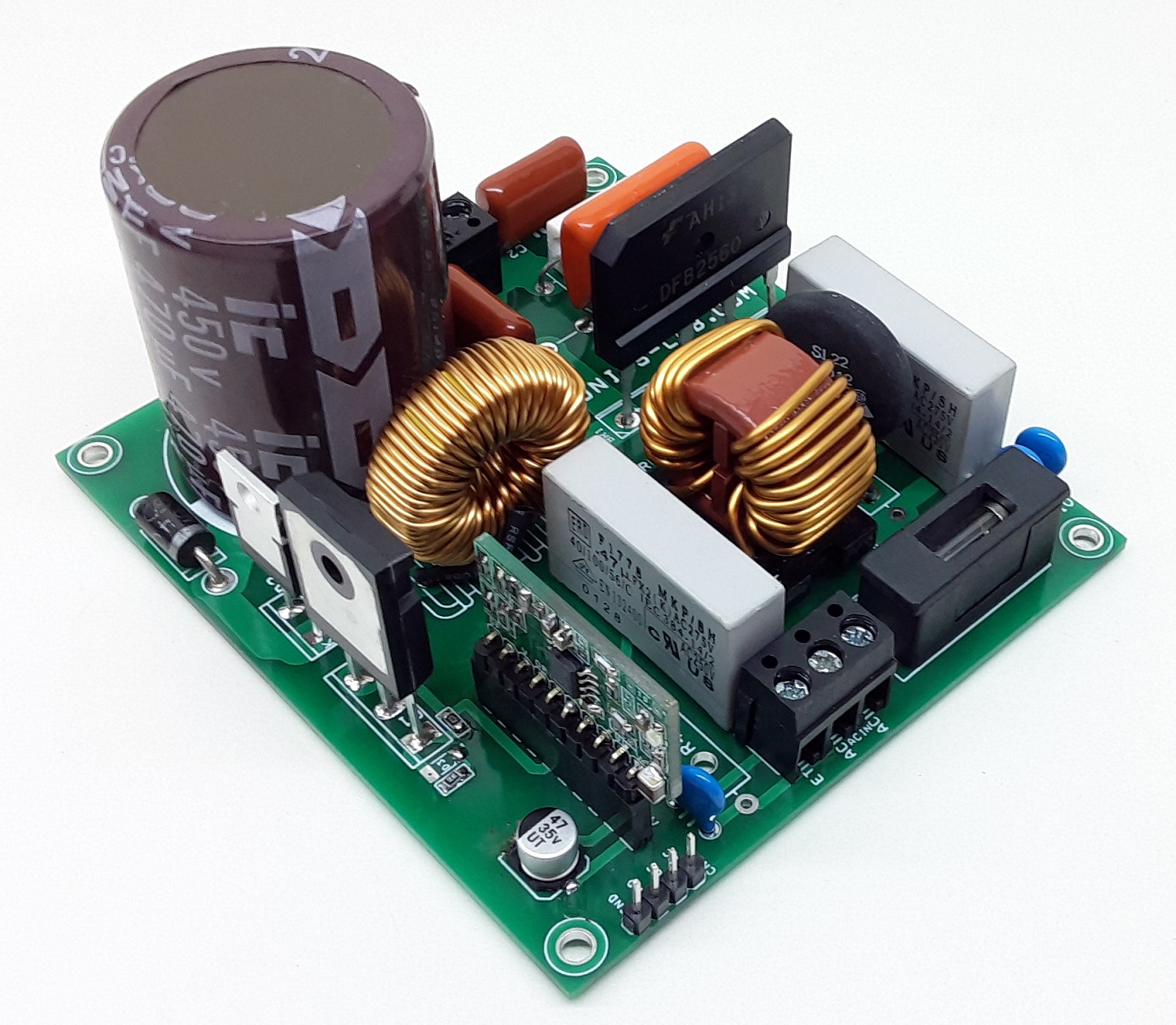
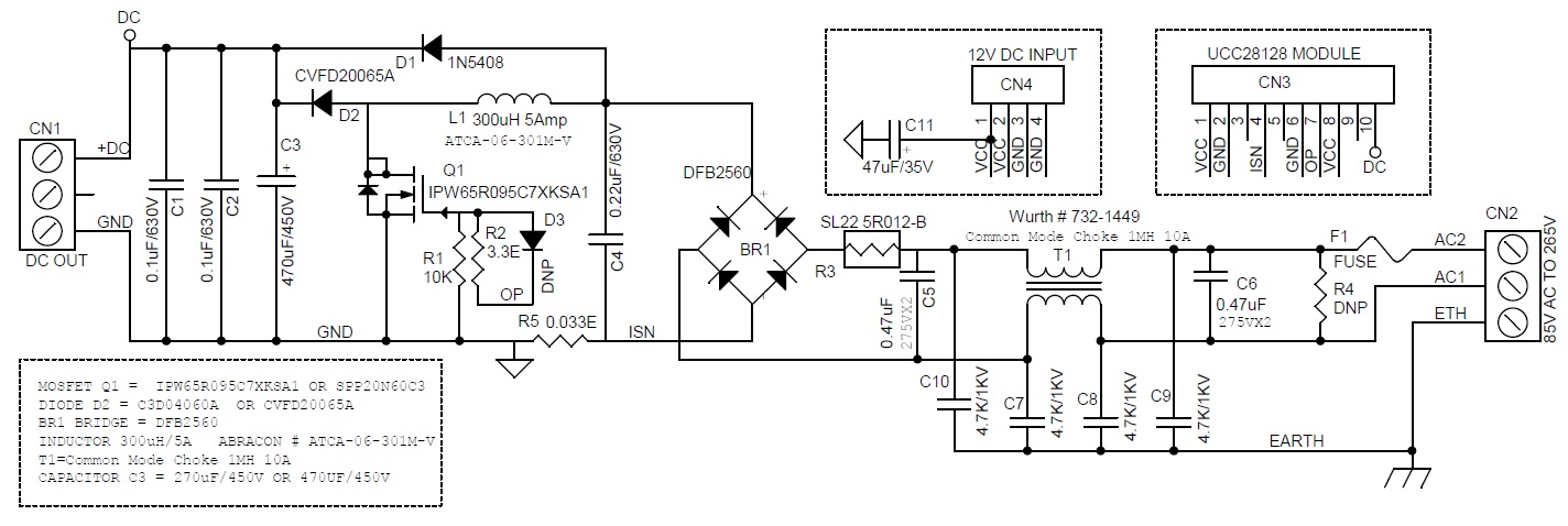
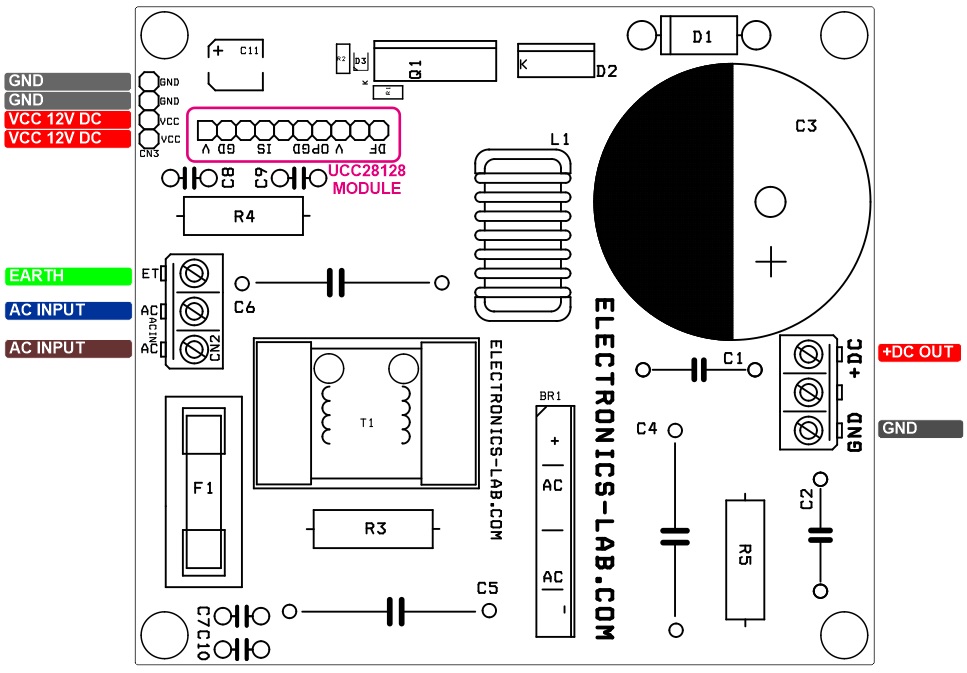
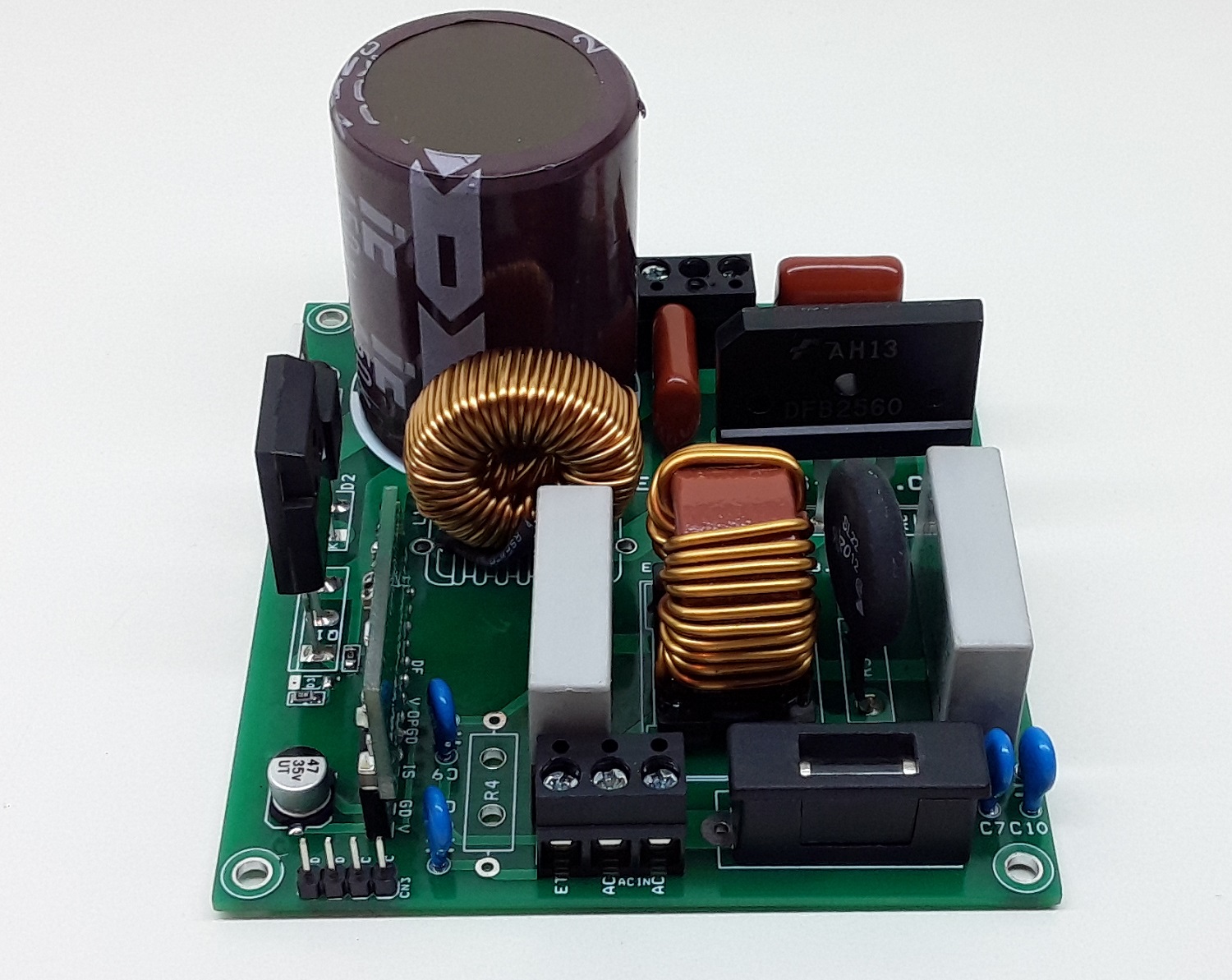
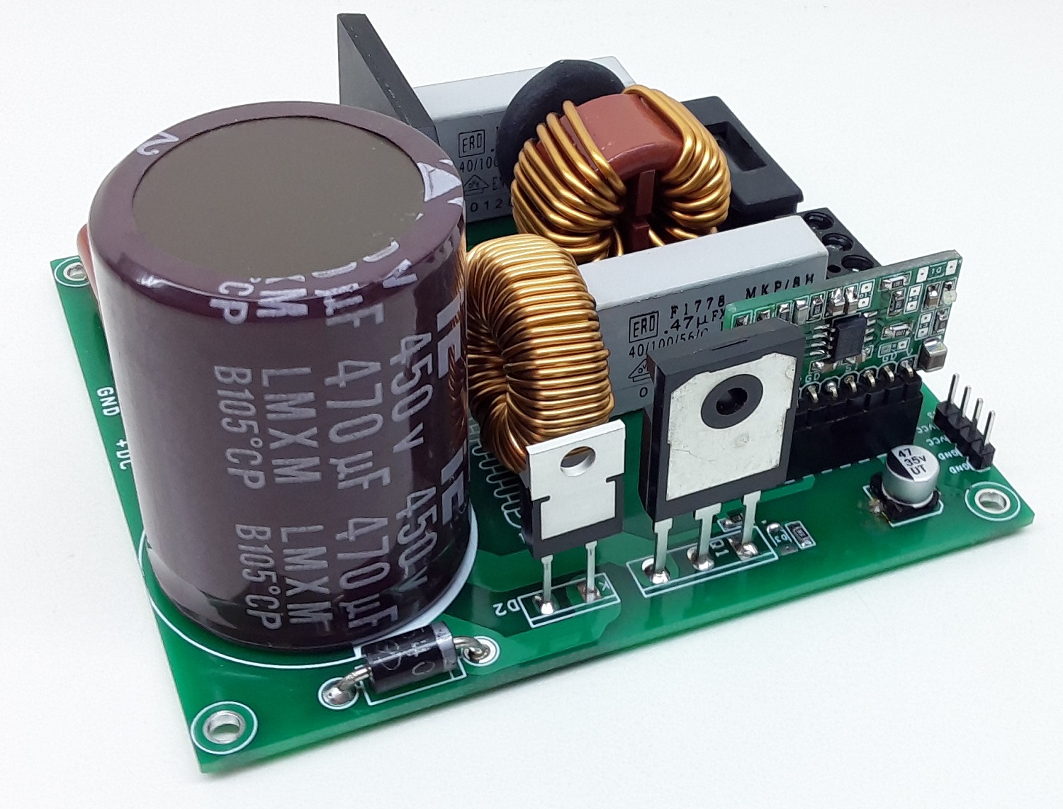
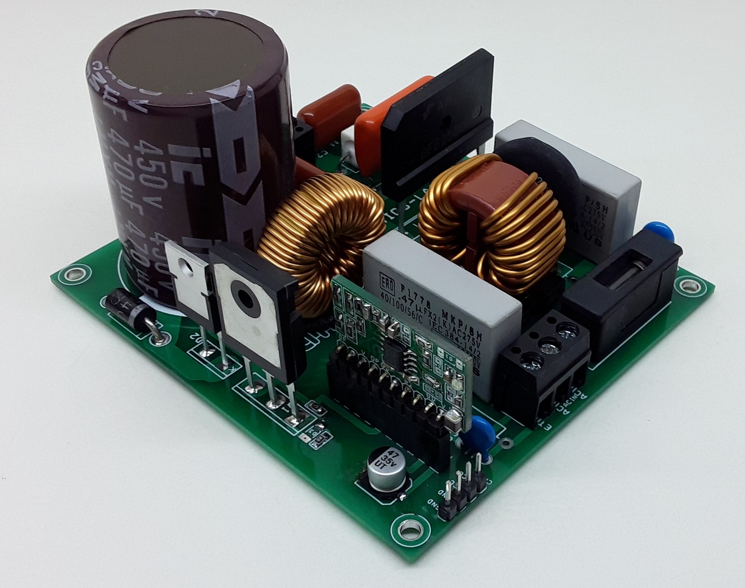
The circuit presented here is a 300W off-line power factor correction (PFC) boost converter providing a nominal regulated output voltage of 375V@ 0.8A of load current. The project accommodates an input voltage range of 85V AC to 265VAC and uses average current mode control at a fixed programmable switching frequency of 116KHz. The project is based on UCCC28180 PFC controller module which incorporates a wide range of protection features to ensure safe system operation. The controller operates under average current mode control at a fixed programmable switching frequency of 116 kHz. Simple external current and voltage loop compensation, along with advanced protection features, make this controller ideal for server and desktop power supplies, industrial power supplies, and white goods. The project includes onboard fuse for short circuit protection, EMI filter, NTC to control inrush current, Bridge rectifier for DC rectification, high voltage/current MOSFET for switching, switching diode, high current inductor, high-value DC bus filter capacitor on the output. This project requires UCC28128 based controller board that can be mounted vertically on the PCB socket.
Heat Sink: Use appropriate heatsink for MOSFET and Switching Diode.
Fan: A fan, capable of 200 LFM to 400 LFM, should be used to maintain component temperatures within safe operating ranges at all times during operation.
Note: This project has 2 blocks, the power board and controller board, information about controller board is available here
The board operates at lethal voltages and has bulk capacitors that store significant charges. Accidental contact can lead to lab equipment damage, personnel injury, and may be fatal. Please be exceptionally careful when probing and handling this board. Always observe normal laboratory precautions.
Features
AC Input Range 85V AC to 265V AC
AC Frequency 47Hz to 63Hz
DC Supply for Logic Circuit 12V DC @ 100mA
300W, 275V DC Output
Average Current Mode PWM Control
Fixed 116Khz Oscillator Frequency
Soft Over Current and Cycle-by-Cycle Peak Current Limiting
VCC Under-Voltage Lockout with Low Start-Up Current
Voltage Regulation Open Loop Detection
Output Over-Voltage Protection with Hysteresis Recovery
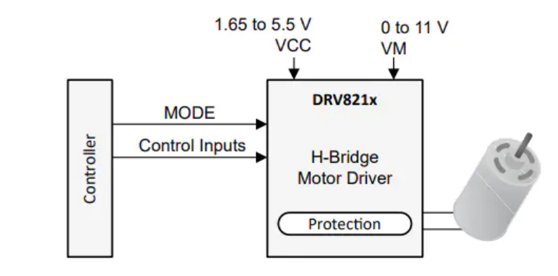
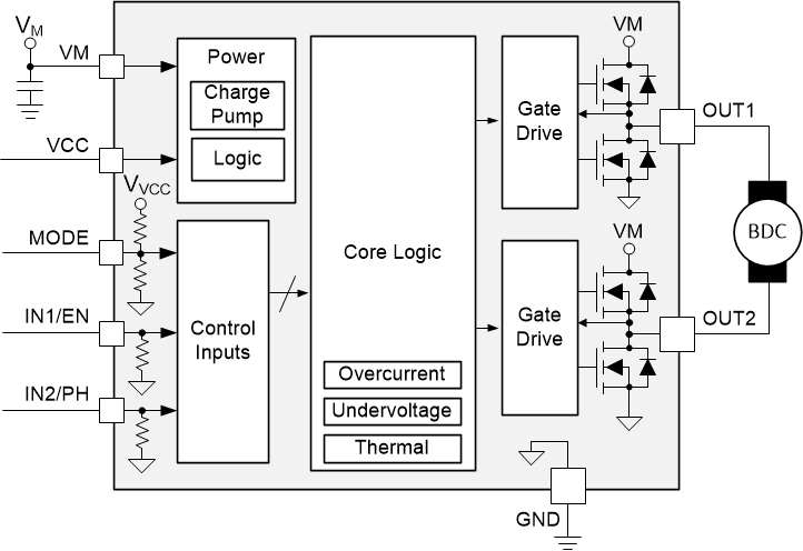
Texas Instruments DRV8212 12V, 2A Low Voltage H-Bridge Motor Driver provides PWM, PH/EN, and half-bridge control interfaces and low-power sleep mode. The DRV8212 Motor Driver is integrated with four N-channel power FETs, a charge pump regulator, and protection circuitry. The triple charge pump architecture allows the device to operate down to 1.65V to accommodate 1.8V supply rails and low-battery conditions. The charge pump integrates all capacitors to reduce the overall solution size of the motor driver on a PCB and allows for 100% duty cycle operation.
The TI DRV8212 supports multiple control interface modes including, PWM (IN1/IN2), phase/enable (PH/EN), independent half-bridge, and parallel half-bridge. Each interface supports a low-power sleep mode to achieve ultra-low quiescent current draw by shutting down most internal circuitry. The device supplies up to 4A peak output current and operates with a supply voltage from 1.65V to 5.5V.
Robust internal protection features are available on the DRV8212, including supply under-voltage lockout (UVLO), output overcurrent (OCP), and device overtemperature (TSD).
The DRV8212 is part of a family of devices that come in pin-to-pin scalable RDS(on) and supply voltage options to support various loads and supply rails with minimal design changes. This family of devices includes DRV8210, DRV8210P, DRV8212, DRV8212P, and DRV8220.
Features
N-channel H-bridge motor driver
MOSFET on-resistance: HS + LS 280mΩ
Drives one bidirectional brushed DC motor
Two unidirectional brushed DC motors
One single- or dual-coil latching relay
Push-pull and bistable solenoids
Other resistive, inductive, or LED loads
1.65V to 11V operating supply voltage range
High output current capability:
Full-bridge: 4A peak
Half-bridge: 4A peak per output
Parallel half-bridge: 8A peak
Multiple interfaces for flexibility and reduced GPIO
Bel Power Solutions’ DC/DC converters are offered in 5V, 12V, 15V, and 48V output options, with high input to output efficiency
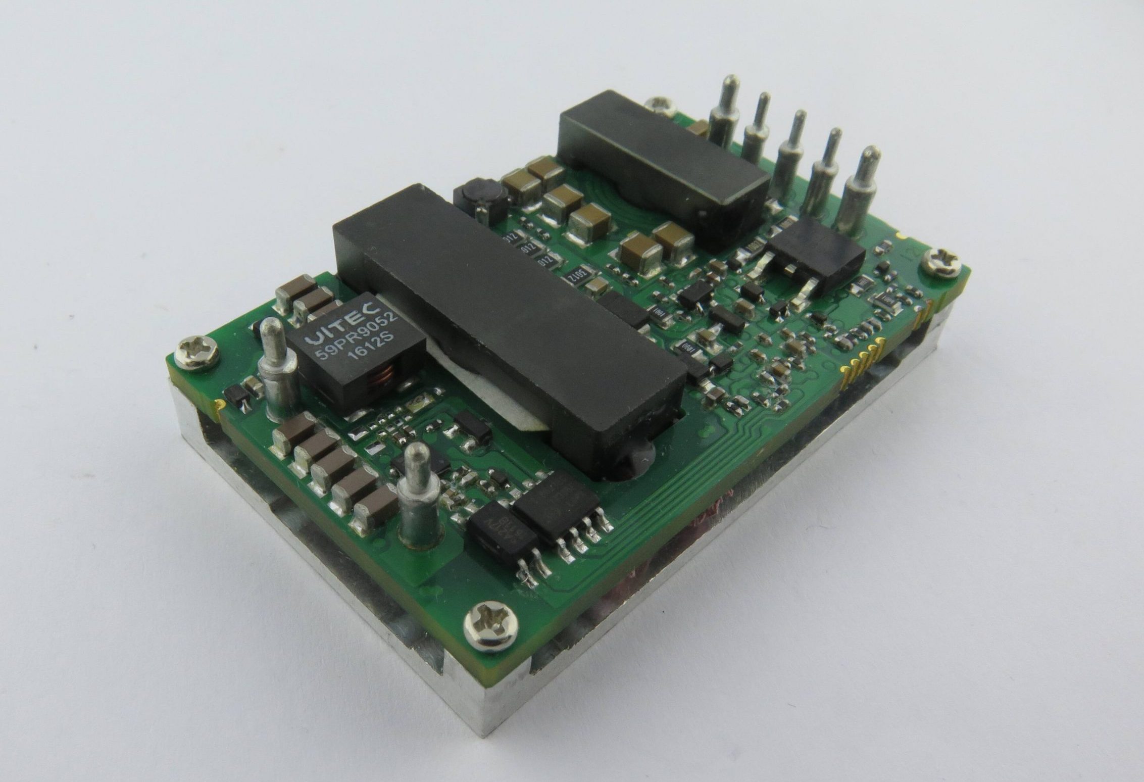
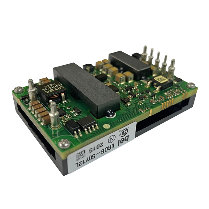
Bel Power Solutions’ 0RQB-50Y05x series isolated DC/DC converter provides 50 W of output power from wide input voltage ranges: 24 V, 48 V, 72 V, 96 V, and 110 V typical with a maximum of 154 V. The quarter-brick converters provide multiple output voltage options: 5 V, 12 V, 15 V, and 48 V. This converter can also provide a 5 V / 5 mA auxiliary supply. When a large hold-up capacitor is added, the converter can still work up to 12 ms when the input supply is interrupted. Bel Power Solutions’ isolated DC/DC converters feature remote on/off, input undervoltage protection, output overvoltage protection, overcurrent, and short-circuit protection. The conformal coated PCB is used for environmental ruggedness for industrial, railway, and other harsh environment applications.
Features/Benefits
Input voltage: 14.4 VDC to 154 VDC
I/O isolation voltage: 3,000 VDC
Ambient temperature: -40°C to +105°C
Hold-up function
Remote on/off
Input overvoltage lockout
Input undervoltage protection
Output overvoltage protection
Overcurrent and short circuit protection
Approved to IEC/EN and CSA/UL 62368-1
Class II, Category 2, isolated DC/DC converter (refer to IPC-9592B)
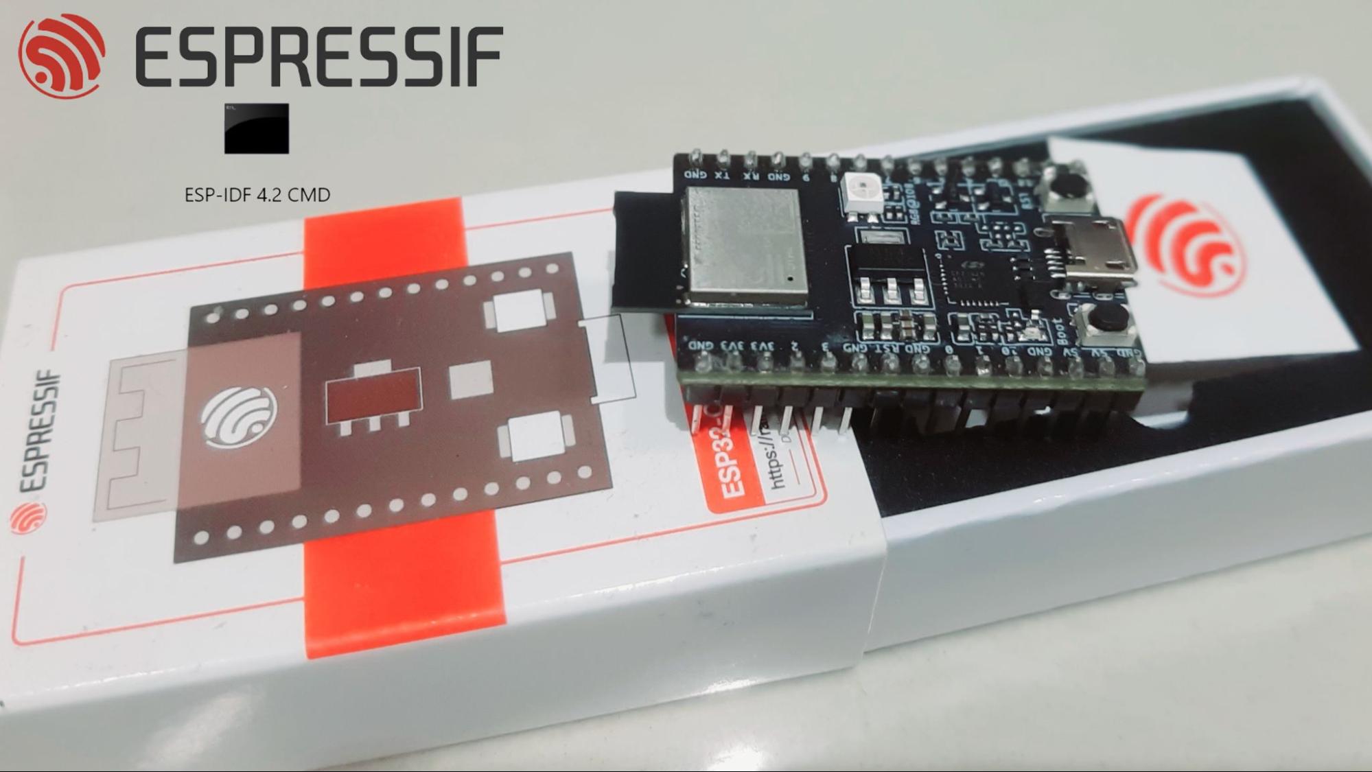
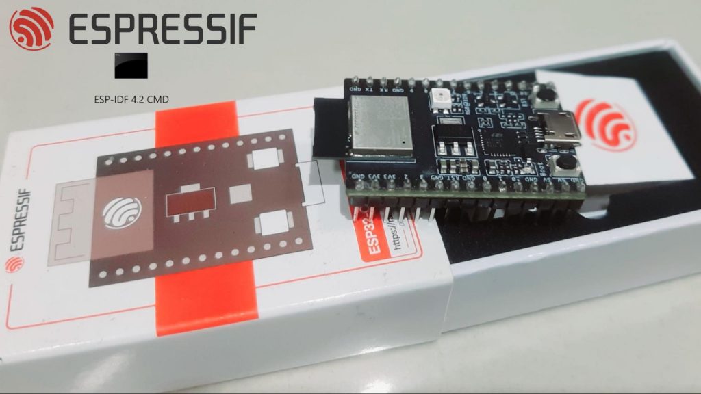
Espressif Systems’ ESP32-C3-DevKit M-1 is an entry-level development board with some interesting features, compatibility, adaptability, connectivity, security, and much more at an affordable price. The ESP32-C3-DevKit M-1 is also known for its small size and low power operation. Apart from this, it also provides a wide range of connection interfaces such as I2C, I2S UART, SPI, GPIO, PWM and also Wi-Fi IEEE 802.11b/g/n (2.4 GHz) and Bluetooth 5 connectivity. The execution of the applications requires the programming of ESP32-C3-DevKITM-1 on ESP-IDF.
You can program your ESP32-C3-DevKITM-1 module with:
ESP-IDF
Arduino IDE
Eclipse Plugin
VS Code Extension
If you want to program your ESP32 board on Arduino IDE, you can follow this article to set up your ESP32 development board with Arduino IDE. In this article, we focus on the programming of ESP32-C3-DevKITM-1 on ESP-IDF.
Getting Started with ESP32-C3-DevKITM-1 on ESP-IDF
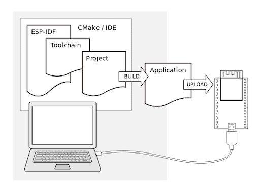
ESP-IDF is a native software development framework for ESP boards containing API, Toolchain scripts with a Command Line Interface (CLI). ESP-IDF follows a conventional approach to upload and run your programs to your ESP board.
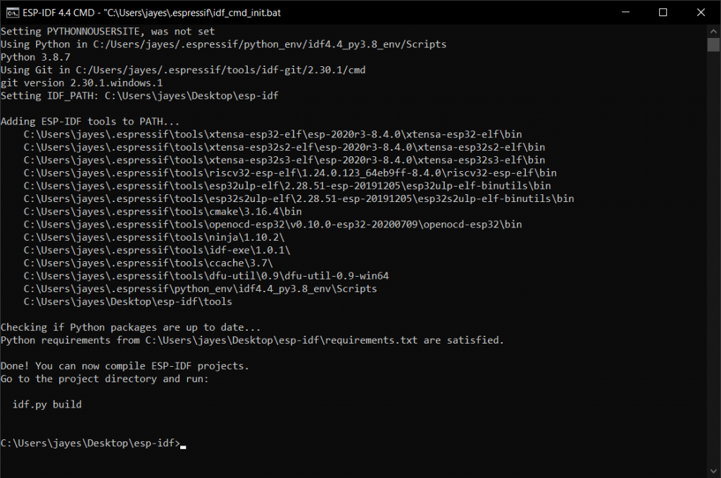
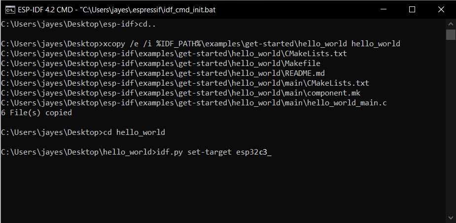
Make a note that you need to install the master version of the ESP-IDF for the ESP32-C3 board series.
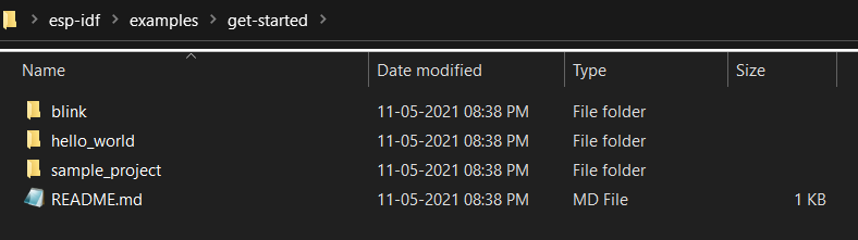
Following the same, you can run examples in the ESP-IDF folder like blink and hello world.
The blink one blinks the onboard RGB LED, which can be controlled from the same file itself.
The ESP-IDF folder also contains some more programs to test out with instructions included in README.md file like Bluetooth, ethernet, wifi, security, protocols, peripherals etc.
Just remember to set a target for the board you are working with. In this case for ESP32-C3-DevKITM-1, you need to execute idf.py set-target esp32c3
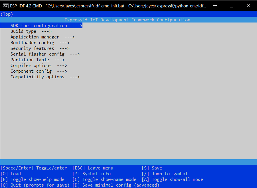
Suppose you get an error in flashing the code regarding the revision of ESP32-C3-DevKITM-1. Go to Idf.py menuconfig -> Component config -> ESP32C3-Specific -> Minimum Supported ESP32-C3 Revision -> REV2 -> Save and Esc, and then you can build, flash your program to your board.
You can also write your own C and C++ language program and flash it onto the board using ESP-IDF.
The ESP32C3 board also comes with an onboard temperature sensor. You can find the code for the same in the ESP-IDF examples folder itself. You can explore many more projects related to microcontrollers in the Projects section.
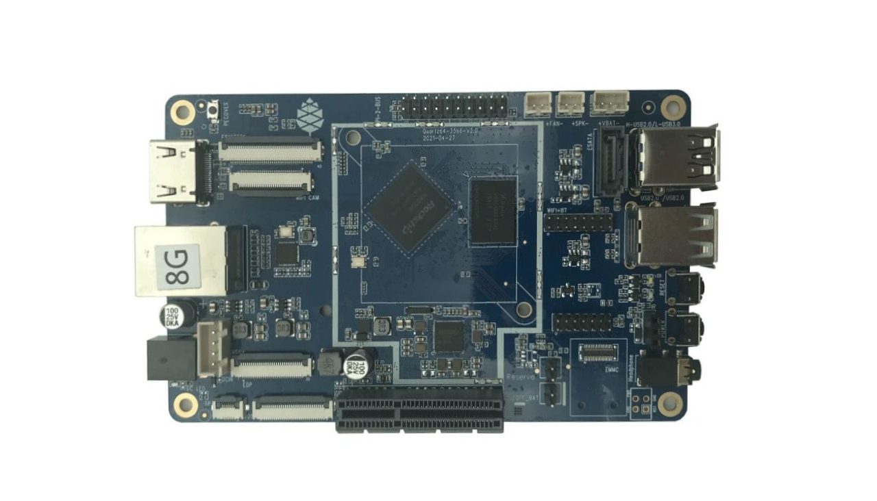
Recently, we have seen the launch of the Firefly ROC-RK3566-PC mini-computer built around the Rockchip RK3566 chip. To continue the emergence of RK3566-powered development boards, the Quartz64, a single-board computer (SBC) has been released by Pine64. With the integrated powerful processor, the SBC provides access to a wide range of features.
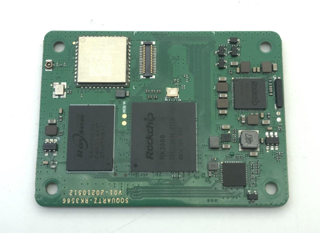
Pine64 has also unveiled the SOQuartz, a new product in the Quartz series. It is a system-on-module based on the NPU-equipped RK3566 that features industry-standard 100-pin high-density connections to resemble the Raspberry Pi Compute Module 4.
The company recommends Quartz64 for developers and expert Linux users who want to contribute to early software development. Additionally, both mainline Linux and Rockchip’s BSP version of Linux have been booted on the platform. Also, the development process is moving rapidly, but it will be months before end-users and industry partners can safely deploy it.
Technical Specifications of Quartz64 Model A
The manufacturer planned to split the Quartz64 SBC line in two, similar to the Raspberry Pi family, with a Model A and a Model B. The 133 x 80 x 19mm Quartz64 model-A harnesses the capabilities of Rockchip RK3566. The RK3566 features a quad-core Cortex-A55 processor clocked up to 1.8 GHz frequency. It also comes with a Mali-G52 2EE Bifrost GPU running at 800MHz, and an integrated neural processing unit (NPU) coprocessor that delivers 0.8 TOPS of performance.
The developer-focused model-A is compatible with LPDDR4 memory options ranging from 2GB to 8GB, depending on the user’s needs. It will also support a Gigabit Ethernet port along with optional wireless connectivity of Wi-Fi 802.11 b/g/n/ac and Bluetooth 5.0. In addition to the MIPI-DSI, eDP, and E-ink interfaces, the SBC supports an option for 16GB to 128GB eMMC modules. It also comes with a microSD card for removable storage.
Talking about the Quartz64 model-B, it is expected to be released in the coming months. According to Pine64, the Model-B will have either a BL-602 RISC-V 802.11n and BLE 5.0 module, which is currently open-sourcing, or an AP6256 802.11ac WiFi + Bluetooth 5.0 module. The compact size makes this device a great choice for education, tinkering, personal projects, and similar applications.
The main difference between the two models is in their connectivity. The Quartz64 Model B lacks the Model A’s SATA port, embedded DisplayPort (eDP) interfaces. Along with this, the MIPI-DSI and -CSI interfaces are two-lane rather than four-lane. The Model B also removes the touch-panel controller and charging circuit. On the other hand, Model B provides user-friendly features. These include onboard Wi-Fi and Bluetooth connectivity and a 40-pin GPIO header rather than the 20-pin header on the Model A. Additionally, Model B has an M.2 slot instead of a PCIe interface.
A developer can build many exciting projects with the Quartz64 SBC. Nevertheless, Pine64 plans to leverage the Quartz64 model-A as a development platform for its next-generation smartphones, laptops, and other devices. Model-B is still under development, while model-A has begun selling to community members.
SOQuartz
The firm also unveiled the SOQuartz module. It is a compute module that may be a drop-in replacement for the Raspberry Pi Compute Module 4. Thus, it has a pair of 100-pin high-density connectors allowing you to connect the module to various carrier boards. SOQuartz will feature the RK3566 SoC, the Azurewave AW-CM256SM WiFi802.11ac Bluetooth and WiFi module with a U.FL antenna connector, and the same software as the Quartz64 boards.
“Flash storage can be added via the eMMC socket (it accepts standard PINE64 eMMC modules) or by having it soldered on the back-side of the PCB. The option for a soldered-on eMMC adds a degree of flexibility for industry partners who may wish to standardize a hardware rollout.”, says Pine64.
The June blog post also provides information on an optional PinePhone keyboard and a PineDio LoRa gateway based on the Pine A64-LTS SBC. However, the Quartz64 Model A is available in two RAM capacities: a 4GB model for $59.99 and an 8GB model for $79.99, both of which are currently available for purchase on the company’s website.
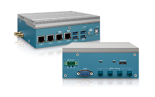
Featuring 6-core NVIDIA Carmel ARM® v8.2 64-bit CPU and 384-core NVIDIA Volta™ GPU, Vecow EAC-2000 Series features power-efficient in a small form factor to empower Edgae AI applications including Traffic Vision, Intelligent Surveillance, Auto Optical Inspection, Smart Factory, AMR/AGV, and any AIoT/Industry 4.0 applications.
Vecow Co., Ltd., a team of global embedded experts, announced the latest Fanless Embedded System EAC-2000 Series. Powered by NVIDIA Jetson Xavier NX module, Vecow EAC-2000 Series delivers great power efficiency in a small form factor. With support for operating temperature from -25°C to 70°C, 9V to 50V wide range DC-in, along with GMSL technology linked with Fakra-Z connectors, EAC-2000 Series brings small size and easy deployment of AI vision and industrial applications including Traffic Vision, Intelligent Surveillance, Auto Optical Inspection, Smart Factory, AMR/AGV, and any AIoT/Industry 4.0 applications.
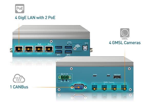
Vecow EAC-2000 is based on the new NVIDIA® Jetson Xavier™ NX module that provides more than 10x the performance of its widely adopted predecessor, NVIDIA Jetson TX2. Featuring 4 GMSL automotive cameras via rugged FAKRA-Z connectors, the EAC-2000 is well suited for industrial and outdoor environments. The EAC-2000 is further equipped with 4 GigE LAN including 2 PoE+ to simplify cable installations and deployments, 6 antennas to enable seamless connectivity, and 1 CANBus to offer faster and robust communication between vehicles.
“Vecow EAC-2000 Series adopts NVIDIA Jetson modules to help accelerate AI performance to the Edge,” said Esther Han, Product Manager, Embedded Systems & Platform Division at Vecow. By integrating Jetson Xavier NX module, EAC-2000 Series is ideally designed for AI vision applications that require intensive-computing, flexible expansion and trusted reliability.”
“We are excited to introduce this new AI platform option to Vecow Arm-based Edge Computing System to our partners,” said Joseph Huang, Sales Manager, Sales & Marketing Division at Vecow. “The brand new launch of EAC-2000 addresses the demands for Edge AI inferring devices that require to be smart, ultra-compact size and high-performance while delivering lower power consumption. We are pleased to have the new enhancement of our wide product range of Edge AI computing system series. The Vecow team is leveraging the NVIDIA Jetson modules to help our partners faster deploy modern AI applications across industries.”
Powered by NVIDIA® Jetson Xavier™ NX module, Vecow EAC-2000 Series delivers up to 21 TOPS AI performance with only 15W. With the support of GMSL camera via rugged Fakra-Z connectors, fanless -25°C to 70°C operations and 9V to 50V DC-in, the EAC-2000 Series is ideally suited for Traffic Vision, Intelligent Surveillance, Auto Optical Inspection, Smart Factory, AMR/AGV, and any AIoT/Industry 4.0 applications.
NVIDIA® Jetson Xavier™ NX, 4 GigE LAN with 2 PoE+, 4 USB 3.1, 2 COM RS-2232/485, 1 SIM, 4 GMSL, 1 CAN Bus, High Performance, Rugged, -25°C to 70°C Extended Temperature
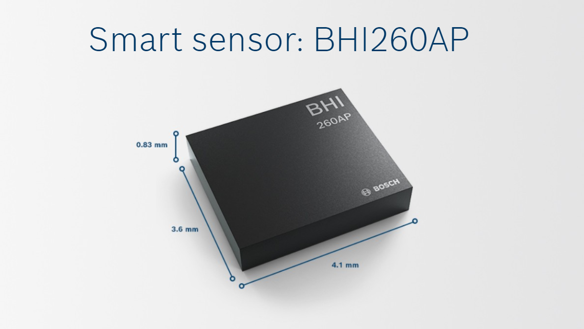
Bosch Sensortec’s all-in-one solution is ideal for always-on sensor applications such as machine learning analytics
Bosch Sensortec’s BHI260AP provides an ideal all-in-one solution for always-on sensor applications such as fitness tracking, pedestrian positioning, machine learning analytics, and orientation estimation. The BHI260AP is a smart sensor that includes a wide variety of software functionalities, a 32-bit customer programmable microcontroller (MCU), and a 6-axis IMU in one package.