R1810 Boost DC/DC Converter is an energy harvesting solution

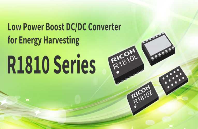
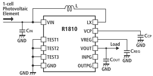
The R1810 Boost DC/DC Converter is an energy harvesting solution designed for powering low current consuming IoT devices by extracting energy from Photovoltaic cells. Target applications include wireless sensors, home and building automation, remote monitoring, presence detection, industrial equipment controls and more.

Tailored specifically to replace the conventional batteries with power supplies operate with photovoltaic cells, the R1810 Boost DC/DC Converter starts up with only 9µW provided from a single cell photovoltaic element. The new IC with its ultra-low power consumption and high-efficiency features enable storing power from any type of 1 cell photovoltaic element. Its start-up voltage is only 0.5 V and once started, the operation continues even if the input voltage drops below 0.2 V. Moreover, it has a high-efficiency performance of 66% at 5 µA output current (Vin=0.5V, Vset=2.6V).

An internally fixed maximum power point voltage (VMP) and output voltage setting (VSET) of the device helps in optimizing the performance of the electrical circuit with respect to the selected energy harvester type. Upon the availability of sufficient energy on the input and increases above the VMP level, the boost DC/DC Converter can transfer energy from the input to the output. On the other hand, when the amount of transferred power exceeds the supplied power from the photovoltaic cell, the input voltage decreases below VMP and the DC/DC converter stops switching.

The converter comes with two monitoring circuits that indicate the status of the conversion process on the respective outputs. First Input Power Good function becomes active when the output voltage level falls below the VOUTUVLO voltage and whether the DC/DC converter stops switching for at least 1.5 seconds. Other Output Power Good function indicates that the output voltage level drops below 50 to 80% of its nominal level, this threshold is internally set and specified by the product version.

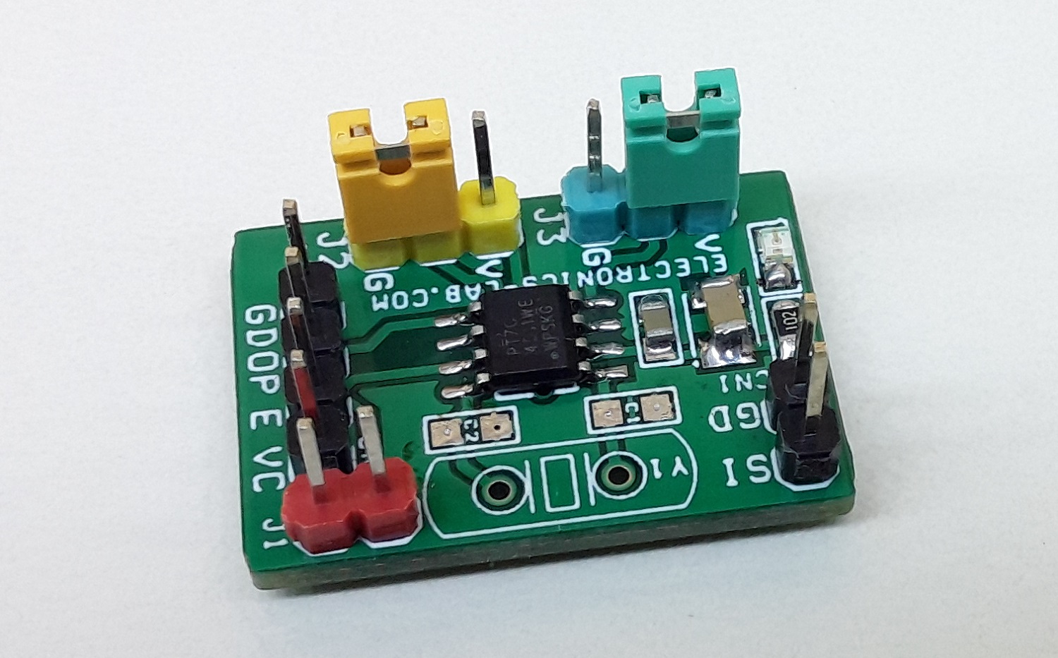
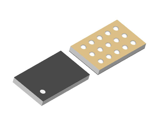
The built-in reverse current protection helps in preventing a current flow from output to input when the light on the photovoltaic cell is blocked. In the event of input voltage drop below the output voltage, the high side MOSFET transistor is turned off to avoid a reverse current draining the energy storage capacitor. The R1810 is available in a regular DFN2735-14 or a tiny WLCSP-15-P1 package. Samples and fully assembled + tested evaluation boards can be purchased from our authorized local distributors and online partners such as Mouser and Digi-Key.

more information: https://www.n-redc.co.jp/en/products/dc-dc-switching-regulator/spec/?product=r1810

VoltLog’s CanLite is an ESP32-based CAN Bus Development Board

CanLite CAN Bus

Yet another development board featuring Espressif Systems’ powerful ESP32 microcontroller. VoltLog recently released the CanLite, a wireless CAN bus hacking, and development board built around an ESP32 microcontroller.

But the CanLite was not meant to be a universal development board, because limited I/Os are available. However, it was designed as a development board tailored to meet the maker’s specific requirements. Yet, many users will find that the features selected by the maker are also suitable for their own projects. Additionally, the board is programmable using the Arduino IDE or ESP-IDF through the onboard JST-SH VoltLink pin header.

Espressif’s ESP32 microcontroller is at the core of this compact CAN Bus wireless board. It is one of the most popular microcontrollers because it is a complete standalone system. Along with this, the dual-core processor provides a lot of processing power as well as Wi-Fi and Bluetooth connectivity for remote control and over-the-air updates (OTA).

The board gets its power directly from the car’s +12V system via the built-in automotive-grade DC-DC step-down converter. On the input of the converter, there is additionally reverse polarity and over-current protection, which adds another layer of safety to the protective measures given by the dc-dc converter itself.

Labeled CanLite CAN Bus

CanLite also features an optional two-channel high-side automotive-grade switch, ST’s VN750PS. It is capable of switching up to 6A per channel with integrated safety provisions. You can purchase the board with one, two, or no high side load switches assembled.
Furthermore, with the inclusion of a voltage regulator, the board can also measure VBAT voltage, allowing it to go into a deep sleep, for example, if the car battery voltage falls below a particular threshold.

Technical Specifications of CanLite ESP32 CAN Development Board

  • Espressif ESP32 processor working at a frequency of 240 MHz.
  • It comes with integrated 4MB of flash storage and also features 520kB of on-chip static RAM (SRAM)
  • Measurement of VBAT voltage uses an onboard voltage divider, and make code decisions based on that.
  • The ST VN750PS, a high-side driver in a SO-8 package, enables you to switch automotive accessories
  • Texas Instrument’s SN65HVD231 is a low power, high performance CAN interface transceiver
  • The onboard 120-ohm termination resistor is configurable via a solder jumper.

Since the ESP32 has the controller part but cannot drive the actual CAN signals or differential signals on a CAN bus, an external transceiver is necessary. Hence, the board employs an SN65HVD231 controller area network (CAN) transceiver, ensuring a robust and compliant interface is provided. It includes many protection features that ensure device and CAN network reliability. Also, the transceiver is compatible with ISO 11898-2 at data rates up to 1Mbps.

You can check out the GitHub repository for exploring the software support of the device. The CanLite ESP32 CAN Development Board is available on Tindie for $30.99. For information, you can visit the official product page on Tindie’s website. Technical specifications and images have also been taken from the product page.

Win an Analog Discovery Pro ADP3450 worth $1295

Portable High-Resolution Mixed Signal Oscilloscope from Digilent.

Digilent has partnered with oemsecrets.com to give away an Analog Discovery Pro ADP3450 worth $1295. To enter simply follow the link below for your chance to win.

ENTER NOW

Get extra entries into the giveaway by following us and sharing this article on Instagram, LinkedIn, Facebook or Twitter using #oemsecrets or @oemsecrets.

Analog Discovery Pro ADP3450

The ADP3450 is the first in the line of Analog Discovery Pro devices and take the analog and digital instruments from the internationally popular Analog Discovery and turn up key functionalities to meet the growing need for professional-level home electronics test benches. At the heart of the device is a four or two channel high-resolution oscilloscope, offering 14-bit resolution at up to 0.5 GS/s.

Full Product Specification

About Digilent

Since 2000, Digilent (a wholly owned subsidiary of National Instruments) has provided embedded engineers, researchers, scientists, and students with cost-optimized products, tools, and application information for innovative, FPGA and SoC based hardware-software systems. Their customizable and flexible solutions will accelerate development time for even the most experienced professionals, while maintaining low barrier to entry for advancing engineers, students, and the perpetually curious.

FIND OUT MORE


UPDATE 25/08/2021

Thanks for entering our latest giveaway. Congratulations to the winner, Jari H.
We would like to thank all of you who entered our latest giveaway, in partnership with Digilent. We’re delighted to announce our Analogue Discovery PRO 3000 Series: ADP3450 Oscilloscope giveaway winner is Jari.

To all our other entrants, not to worry, we will be launching our next giveaway in partnership with Farnell shortly!

Nicla Sense ME: Arduino’s Upcoming Smallest Form Factor AI Development Board

Nicla Sense ME

You don’t usually find a new AI development board by Arduino in the documentation before the release. For the Bosch Sensortec IoT Innovation Challenge, the first batch of the AI board has been sent to the participants. If you are interested in getting your hands on this new Arduino Nicla Sense ME, then you might have to wait until Autumn for the release. As of now, there is no information on the pricing of the board. The AI development board is built around the Cortex-M4 nRF52832 microcontroller, integrated with a rich set of sensors packed in the smallest form factor yet.

The AI development board, Nicla Sense ME, gets the industrial sensors onboard, such as temperature, humidity and movement. If you plan to use BLE, the 9-axis inertial measurement unit, along with the Bluetooth Low Energy connectivity, can help you build exciting wireless projects. Since the board was primarily designed for the Bosch Sensortec IoT Innovation Challenge, it gets all the industrial-grade wireless sensing networks with the onboard BHI260AP, BMP390, BMM150 and BME688 Bosch sensors.

One of the important things to note in this AI board is that it does not support Wi-Fi wireless connectivity but is designed with an ANNA B112 Bluetooth module. This can be one of the best boards for your IoT remote applications as it can accurately measure rotation, acceleration, pressure, humidity, temperature, air quality and CO2 levels.

Nicla Sense ME Prototype

As mentioned earlier, the Boash BHI260AP is an AI smart sensor hub with integrated IMU that features Fuser 2 CPU core, 6-axis IMU, and AI features like self-learning AI software for fitness tracking and relative and absolute orientation. The Boash BMP390 is a high-performance pressure sensor with an operation range of 300-1250 hPa. It is also equipped with a Bosch BMM150 3-axis magnetometer and Bosch BME688 environmental sensing with artificial intelligence.

The Nicla Sense ME features a built-in RGB that can be utilised as a feedback component for applications. The LED is connected through I2C; therefore, specific functions need to be used to operate the LED colors.” The Arduino Nicla Sense ME can be powered through a micro-USB, ESLOV or VIN.

To get started with the board, you just need Arduino Desktop IDE, where you connect the Arduino Nicla Sense ME to your computer through a micro-USB cable. This will also power the AI, development board. For more information on getting started and using the specific sensors on the board, please visit the product page.

Build Smart Home Solutions in 10mins using ITEADs PSF-B Series 1-4 Gang Ultra Low Power ESP8285 Wi-Fi Switch Module

There is absolutely no end to the number of different types of modules and devices in which the ESP family of WiFi modules/microcontrollers have been featured, thanks to their integrated nature and small form factor. While the ESP8266 and ESP32 variants are the most known, other less-known versions like the ESP8285 have recently been garnering popularity with several products based on it, including the recently released PSF-B 4-gang Wi-Fi Switch Module, by china-based home automation solution provider; ITEAD.

A 1-4 gang ultra-low-power Wi-Fi switch module, the ESP8285-based PSF-B Switch module was designed to enable rapid development of WiFi-based, home automation switch solutions. It comes with the ability to switch up to four independent household points/appliances and can be controlled via connected pushbuttons, or controlled remotely by connecting it to a privately developed, or publicly available app like ITEAD’s eWeLink.

Key Features:

  • Built-in 32bit MCU, and can double as an application processor
  • Support wireless 802.11 b/g/n standard
  • Wi-Fi @2.4 GHz, support WPA/WPA2 security mode
  • +20.5dBm maximum output power in 802.11b mode
  • Support device button control and Wi-Fi remote control
  • a)In the normal state: click the button (IO0 pulls down for more than 100ms) to control the relay on and off (IO12 output high/low level
  • b)In the pairing mode: click the button to exit the pairing mode.
  • Support timer schedule – including single, count down, repeat, and loop timer, see details in 4.5.
  • Support compatible pairing mode /quick pairing mode
  • Power-on status -The power-on switch status can be configured on or off through the APP, and the default power-on status is off.
  • Support OTA upgrade

As one would expect from a solution developed by a home automation powerhouse like ITEAD, a one-stop-shop for all things SonOff and Nextion, who understands the latest trends and standards for home automation devices, the PSF-B Wi-Fi Switch Module comes with adequate support for mobile devices and Internet of Things applications. For example, thanks to the eWeLink support, devices built on the module will automatically have support for voice control, and several smart home platforms like Alexa, Google Assistant, Alice, and Bixby to mention a few. The devices will also enjoy several benefits of the eWeLink ecosystem like access to more third-party platforms as soon as they are available without the need for any modification to the device.

Some highlight features of the PSF-B 4-gang Wi-Fi Switch Module include:

  • Built-in 32bit MCU, and can double as an application processor
  • Support wireless 802.11 b/g/n standard
  • Wi-Fi @2.4 GHz
  • Wireless network type: STA/AP/STA+AP
  • Encryption mechanism: WEP/WPA-PSK/WPA2-PSK
  • Encryption type: WEP64/WEP128/TKIP/AES
  • +20.5dBm maximum output power in 802.11b mode
  • Support device button control and Wi-Fi remote control
  • Support timer schedule – including single, count down, repeat, and loop timer, see details in 4.5.
  • Support compatible pairing mode /quick pairing mode
  • Power-on status -The power-on switch status can be configured on or off through the APP, and the default power-on status is off.
  • Support OTA upgrade
  • eWeLink Support
  • Conditions: VDD=3.3V±10% , GND=0V; test at room temperature 25°C.
  • Operating Voltage: 2.7V~3.6V
  • GPIO drive capability: Max: 12mA
  • Working current: Average current: ≈80mA ,
  • Maximum working current: 210mA
  • Standby: <200uA
  • Operating temperature: 0℃~45℃
  • Storage condition: Temperature: -10℃~75℃ ,
  • Relative humidity: 20%RH~80%RH

According to ITEAD the idea behind the module was to ensure designers need an average of 10 minutes to build their own smart switches, as all one will need is to simply connect the power supply to the module’s periphery, along with buttons to the input and relays to the output pins of the module. With the ultra-small form factor, designers have the freedom and wiggle room to go with an overall form factor and product size that suites their brand or the need of their products.

The PSF-B 4-gang Wi-Fi Switch Module is currently available for sale on ITEAD’s website, starting at $2.50 which is quite fair for a module of its caliber.

More information on the PSF-B 4-gang Wi-Fi Switch Module, its features, and potential application can be found on the product’s page on ITEADs website. 

Meet the New 5G Ready Carrier Board from AAEON’s UP! Bridge the Gap

Netherlands bands Embedded computing solutions manufacturer, AAEON Technology Europe, last week announced the launch of their latest carrier board; the UP Connect Plus, which was designed to add 5G capability to its popular UP Core Plus and UP Xtreme platforms.

The UP Core Plus, an ultra-compact, high-performance, and fanless edge computing module, and the Up Xtreme, an even more powerful Edge AI inference solution, both, on different levels, provide users with the computing power needed to develop AI and IoT powered smart applications that businesses depend on to help them optimize, monitor, manage and secure their operations.  However, as this number of devices grow, with increased interconnectivity, network traffic, and amount of data being shared, etc., solution providers and users are constantly looking for better ways to overcome latency, improve bandwidth to ensure seamless movement of data, and overall network reliability which is all of which 5G promises.

Meeting this demand is one of the major reasons why the Up Connect Plus was developed to provide access to 5G capabilities for the Up Core Plus and UP Xtreme platforms which already come with WiFi and LAN onboard.  The Up Connect Plus provides a 5G compatible port via its M.2 3042/3052 colayo through which users can add a 5G module card and bring astonishing 5G speeds to any UP Core Plus or UPXtreme based AI application.

Asides from the 5G Port, the UP Connect Plus also offers three additional Gigabit LAN ports to extend functionalities of the UP Core Plus and UP Xtreme platforms. With users being given the opportunity to choose between two types of Intel® Ethernet ports that deliver gigabit speeds as the UP Connect Plus comes in two versions including; the UP Connect Plus i211 which features three Intel® Ethernet Controller I211-AT Gigabits ports and the UP Connect Plus i210 which features three Intel® Ethernet Controller I210-IT ports with Time-Sensitive Networking (TSN) and support for a wide temperature range which comes in hand in industrial applications that require synchronization and precision timing.

Solution developers can use TSN together with real-time features on Intel® architecture to synchronize networks of devices for improved timely behavior of industrial systems across applications like Smart factories, Cobots, and general autonomous systems.

Highlight specifications of the Up Connect Plus include;

  • Support for 5G module (M.2 3042/3052 colay) with micro-SIM card port
  • 3x Intel® Ethernet Controller I210-IT (wide temperature and TSN) OR 3x Intel® Ethernet Controller I211-AT
  • USB 3.0 Type-A (UP Core Plus only)
  • 1x 2 channel PCIe Switch
  • Suitability for Industrial Operations with operating temperature between 32°F ~ 140°F (0°C ~ 60°C)

The UP Connect Plus is now available for sale at AAEON’s UP! Bridge the Gap store, with prices starting from $84 without shipping.

More information on UP Connect Plus can be found on the product’s announcement page on AAEON’s UP-Board website. 

Get this sunlight readable display for Raspberry Pi at just $110

Sunlight readable display may not be a new concept for most developers working on the Raspberry Pi single-board computers. For those who do not know how it works, then as the name suggests, a sunlight-readable display operates in direct sunlight or harsh light conditions. Those working on any application that requires capacitive touch LCD compatible with Raspberry Pi have seen several other products with one, especially from SparkFun Capacitive Sunlight Readable LCD Board if you are only looking for a cheap yet powerful capacitive touch screen display for your Raspberry Pi 3/4 for any industrial or commercial applications.

This newly launched Sunlight Readable Touchscreen HDMI Display comes with a decent-sized 5-inch screen with capabilities to operate on most SBCs like the Raspberry Pi, BB Black, Banana Pi, and other Mini PCs. With these points, we have some specifications that you’d want to look at before getting into the customizable capabilities of the sunlight-readable display.

Specifications:

  • Product: MakerPlane Sunlight Readable Display
  • Dimensions: 121mm x 95.2mm
  • Resolution: 800 x 480 crisp
  • Screen size: 5-inch IPS
  • Aspect ratio: 16:10
  • Brightness: 1100 cd/m2
  • View angle: Horizontal:170° Vertical:150°
  • Interface: HDMI
  • Touch type: Single point capacitive touch screen
  • Module structure: LCD Display + CTP Touch + PCB
Sunlight Readable Display Applications
MakerPlane’s LCD display featuring an avionics instrument

Along with these specifications, when you buy the product, one important thing is the powering options for the hardware. The manufacturer has provided the sunlight-readable display with a 5V 2A minimum power supply through a micro-USB or GPIO module. With all these best-in-class specifications, the buyer gets several other things in the package included, has one 5-Inch Screen, an HDMI connector, a Micro HDMI, a connector screws pack (4pcs), and a 16GB SDcard storage.

Comparison between a normal LCD screen and MakerPlane’s sunlight-readable display.

MakerPlane sunlight-readable display compared to other displays, seems to be easy on your eyes that makes it a perfect choice for gaming or always-on display applications. With such displays, the designers can design navigational instruments or even display news headlines. Also, with easy interfacing, it becomes easy to explore all the capabilities that aid your applications with minimal cost than other displays. With all these features and peculiarities, the users are pretty happy with the designed product that gives you not only a wide viewing angle but also good brightness at a reasonable price.

Video

When it comes to customizing the display, you can control the brightness using PWM. But when doing this, make sure you look at the detailed guide on the product page because the commands for Raspberry Pi 3B/3B+ are different from the latest Raspberry Pi 4B. Those designers working on the Raspberry Pi 4B need to update the wiringPi GPIO library, which can be done with the SBC connecting to the internet. With similar commands, you can control the brightness by keeping the X value between 0 to 1024, with 1024 being the darkest and 0 being the brightest.

Photos

For Raspberry Pi 3B/3B+

gpio -g pwm 18 1024
gpio -g mode 18 pwm
gpio pwmc 1000
gpio -g pwm 18 X

For Raspberry Pi 4B

gpio -g mode 18 pwm
gpio pwmc 4095
gpio -g pwm 18 X

You can also rotate the display with some simple commands provided by the manufacturer, but note that you also need to configure for the touch with these commands, which does not automatically change with the screen rotation. For this, you can refer to the guide with detailed commands but only for Raspberry Pi.

If you are looking to buy this reasonably yet powerful display for your favorite SBC, then head to the product page available for sale at just $109.95 with additional shipping charges.

3 Phase AC input – DC Output – High Voltage DC Power Supply (2KW)

Although this power supply design is specific to the Intelligent Power Modules (IPM) VFD drives, high voltage boost converters, high voltage battery chargers, etc, the concept and circuit design may be used for any power supply that requires a high voltage output of up to 800V DC and 4 A. Since it is an unregulated power supply the output will depend on AC input voltage. The circuitry includes a passive EMI filter consisting of elements C8, C9, C4, T1, and L1.  Bridge rectifier D1, R1 for inrush current protection, and a relay RL1 for soft powering up and reducing conduction losses in steady-state. 4 x electrolytic capacitors C2, C3, C6, C7 are used for buffering the rectified DC bus voltage, bleeding resistors R1, and R2 provided to discharge the DC bus capacitor after power off. It is advisable to use a heatsink for the bridge rectifier. Inrush current circuit requires 12-15V DC @ 80mA. Choose appropriate fuse as per current requirement. The relay takes care of the inrush current. It is important to switch ON the 12V-15V DC and 3phase power same time.

We have tested this power supply with Input 3 Phase 430V AC, Output 620V DC, Continued Current 5A, but it is advisable to use it at max 3A continued current.

Application: VFD Drives, AC Servo Drivers, High Voltage Battery Chargers, ZVS Drivers, High Voltage Inverters, High Voltage DC-DC Converters

Safety precautions

The board operates at lethal voltages and has bulk capacitors that store significant charges. Accidental contact can lead to lab equipment damage, personnel injury, and may be fatal. Please be exceptionally careful when probing and handling this board. Always observe normal laboratory precautions.

Features

  • Nominal Input Voltage 3 Phase 100V to 480V AC
  • Output Depend on input AC Supply
  • Output Current Continues 3Amps (Maximum 5 Amps)
  • On Board EMI Filter
  • On Board High wattage resistor for inrush Current
  • On Board Relay for soft powering up and reducing Power Losses
  • On Board Fuse for Short Circuit/Over Current Protection
  • Screw Terminals (Barrier) for Easy Connections
  • Logic Supply 12-15V for inrush Control Relay Circuit
  • PCB dimensions: 206.37 x 75.56 mm

Schematic

Parts List

NO.QNTYREF.DESC.MANUFACTURERSUPPLIERSUPPLIER PART NO
11CN13 PIN BARRIER STRIP PITCH 9.5MMON SHORE TECHDIGIKEYED2972-ND
21CN24 PIN BARRIER STRIP PITCH 9.5MMON SHORE TECHDIGIKEYED2973-ND
31CN34 MALE HEADER PITCH 2.54MMWURTHDIGIKEY732-5317-ND
43C1,C4,C50.1uF/1KVKEMETDIGIKEY399-PHE450PD6100JR06L2-ND
54C2,C3,C6,C7470uF/450VRUBYCONDIGIKEY1189-1975-ND
62C8,C94.7KPF/3KVTDKDIGIKEY445-181053-ND
72C10,C1110uF/25VNICHICONDIGIKEY493-5953-ND
1D1GUO40-12NO1IXYSDIGIKEYGUO40-12NO1-ND
2D2,D31N4007DIODE INCORPDIGIKEYS1MBDITR-ND
1F1COVER FUSEKEYSTONEDIGIKEY36-3576C-ND
1F1FUSEKEYSTONEDIGIKEY36-3576-ND
1F1FUSE LITTILE FUSEDIGIKEY0FLQ015.HXR-ND
1L1220uH/7.1AWURTHDIGIKEY732-2285-ND
1Q1BC817NEXPERIADIGIKEY1727-2919-1-ND
1RL1Relay 12V TEDIGIKEYPB2355-ND
1R1100E/10WVISHAYDIGIKEYMRA12-100-ND
2R2,R3270K/3WVISHAYDIGIKEYBC270KW-3JCT-ND
1R410K 5% SMD SIZE 0805MURATA/YAGEODIGIKEY
1R51K 5% SMD SIZE 0805MURATA/YAGEODIGIKEY
1T11MH 10A COMMON MODE CHOKEWURTHDIGIKEY732-1449-ND

Connections

Block Diagram

Gerber View

Photos

Video


GUO40-12NO1 Datasheet

Clock Multiplier – Crystal Frequency Generator using PT7C4511

This is an easy-to-build project and it is the most cost-effective and high-performance frequency multiplier, which instigates analog phase lock loop techniques. The circuit provides high-quality, high-frequency output from lower frequency crystal or clock input. The project can be used as a crystal frequency oscillator, clock multiplier and frequency translation. Using phase-locked-loop (PLL) techniques, the device uses a standard fundamental mode, inexpensive crystal to produce an output clock up to 200Mhz.  On-board jumpers are provided to select from nine different multiplication factors, which output many common frequencies.  The device also has an output enable pin that tri-states the clock output when the enable pin is taken low. The chip is intended for clock generation and frequency translation with low output jitter.

Refer to the table below for jumper settings to change the frequency multiplexing.

  • Connections for Clock Input: CN1 Clock input 1- 50Mhz, Use J2, and J3 for frequency output settings.
  • For Internal Clock Generator: Use crystal Y1, Capacitor C1, and C2

A parallel resonant, fundamental mode crystal should be used. The device crystal connections and capacitor connections are provided. These capacitors are used to adjust the stray capacitance of the board to match the nominally required crystal load capacitance. Because load capacitance can be only be increased in this trimming process. Crystal Capacitors, if needed, must be connected from each of the pins X1 and X2 to the ground.

The value (in pF) of these crystal capacitors should equal C-L x 2 in this equation, C-L=crystal capacitance in pF. Example: For a crystal with a 15pF load capacitance, each crystal capacitor would be 30pF.   

Features

  • Power Supply 5V DC (Range 3 to 5 V DC)
  • Zero ppm multiplication error
  • Output Load 12mA Max
  • Input crystal frequency of 5Mhz to 30Mhz
  • Output Duty Cycle 50%
  • Input Clock Frequency of 1-50Mhz
  • Output Clock Frequencies up to 200Mhz
  • 9 Selectable Frequencies Controlled by Jumper
  • Peak to Peak Jitter Less than 200ps over 200ns Interval (100-200Mhz)
  • Low Period Jitter 20ps (100-200Mhz)
  • Tri-States Output for Board Level Testing
  • PCB dimensions: 25.72 x 17.94 mm

Schematic

Parts List

SR.QNTY.REF.DESCMANUFACTURERSUPPLIERSUPPLIER PART NO
11CN12 PIN MALE HEADER CONNECTOR PITCH 2.54MM WURTHDIGIKEY732-5315-ND
21CN24 PIN MALE HEADER CONNECTOR PITCH 2.54MM WURTHDIGIKEY732-5317-ND
33Y1,C1,C2DNP
41C310uF/16VMURATA/YAGEODIGIKEY
51C40.1uF/50VMURATA/YAGEODIGIKEY
61D1LED RED SMD SIZE 0805OSRAMDIGIKEY475-1278-1-ND
71J12 PIN MALE HEADER PITCH 2.54MM DIGIKEY732-5315-ND
82J2,J33 PIN MALE HEADER PITCH 2.54MMDIGIKEY732-5316-ND
91R11K 5% SMD SIZE 0805MURATA/YAGEODIGIKEY
101U1PT7C4511 SOIC8DIODE INC.DIGIKEYPT7C4511WEXDICT-ND
113SHUNTJUMPER-SHUNTSULLINSDIGIKEYS9001-ND

Connections

Jumper Selection

Block Diagram

Gerber View

Photos

Video

PT7C4511 Datasheet

First commercially available superconducting quantum processor

The Dutch startup QuantWare has announced the launch of the world’s first commercially available superconducting processor for quantum computers (QPU).

This is the first time superconducting quantum processors have been made available ‘off the shelf’, and is being seen as a development with the potential to significantly accelerate the quantum computing revolution.

Quantum technology promises to significantly expand the amount of data computers are able to process, which could have huge implications across A.I., medicine, business intelligence, and cybersecurity. However, in what is still a new, developing industry scaling is difficult.

Companies building parts for quantum computers need qubits, the microscopic objects that make quantum computing possible, but it is often cost prohibitive for them to produce them themselves. QuantWare’s superconducting QPUs are intended to eliminate that barrier and may be instrumental in accelerating the development of the quantum computer market.

Superconducting is the leading and most mature approach to quantum processors – Google achieved “quantum supremacy” in 2019 using superconducting QPUs. While other QPUs are already available “off the shelf”, this is the first time a superconducting QPU has been easily available in productised form, leveling the playing field for quantum experimentation.

QuantWare’s proprietary product, Soprano, is a 5-qubit QPU which is seen as sufficient for the immediate customer base QuantWare expects to attract, namely research institutions and university labs.

“The race towards useful Quantum Computation is heating up, but still reserved to a small group of companies. By making QPUs more available, we will speed up the development of practical quantum-driven solutions to the world’s biggest problems.”

said QuantWare co-founder Dr. Alessandro Bruno.

Another way to achieve “Quantum Advantage” is by designing a chip specifically for a particular application and QuantWare is looking to exploit this by making co-designed QPUs together with software companies to allow them to develop processors specialized in their algorithms.

more information: www.quantware.eu

TOP PCB Companies