We have seen various SBCs being released since late 2020 to 2021, however, 10 of these SBCs will be summarized alphabetically below.
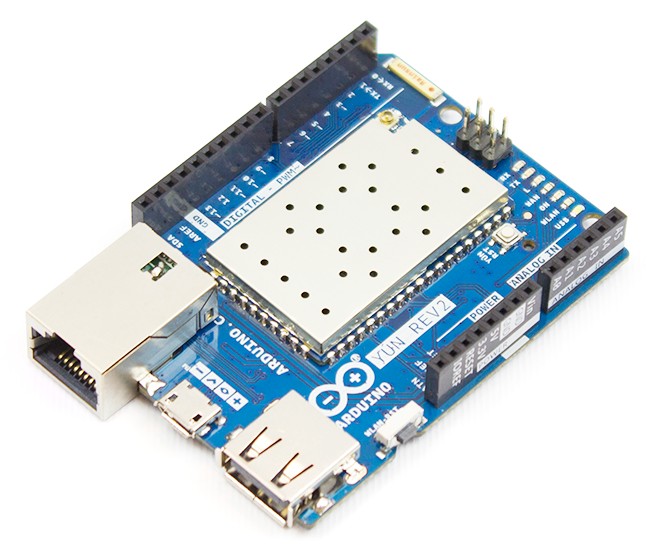
Arduino Yun Rev 2
The Yún rev. 2 is a reboot of its original, MIPS-based Arduino Yun, with the power of a Linux based system that enables advanced network connections and applications. It offers a WiFi-enabled, 400MHz AR9331 SoC running OpenWrt Linux with an ATmega32U MCU that runs Arduino code. The board is also equipped with a microSD slot and USB host, micro-USB, and 10/100 Ethernet ports. Connecting to your WiFi or wired network is easy thanks to the Yún Web Panel and the dedicated ”YunFirstConfig” sketch. The Web panel enables you to manage your shield preferences and upload your sketch. The Yún rev. 2 utilizes the Bridge library and so extends the board capabilities by using the Linux processor. The board is also open source.
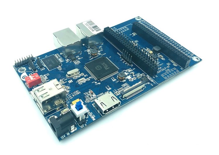
Banana Pi BPI-F2S
This board was announced in Nov. 2019, in collaboration with SunPlus. The BPI-FS2 is built around the SunPlus SP7021 (Plus1) SoC. The 110 x 75mm BPI-F2S features a 720p HDMI port, MIPI-CSI, 2x 10/100 Ethernet, 2x USB 2.0, micro-USB, TPM, and debug I/O. Additional features include a HAT-compatible 40-pin GPIO link, and dual 50-pin connectors that support a Trenz Electronic TE0725LP-01-100-2D module equipped with an Artix-7 FPGA and 95 I/Os. Images are available for Debian Buster, Fedora 31 Mate, Ubuntu 18.04, Kail Linux, Mozilla IoT Gateway, and CentOS, all with Linux 4.19.37. The source is found on GitHub, and SinoVoip has posted schematics and other open hardware resources.
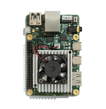
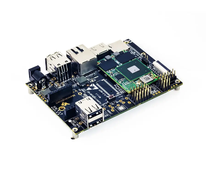
Coral Dev Board
Coral is a complete toolkit for building products with local AI. Its on-device inferencing capabilities enable you to build products that are efficient, private, fast, and offline. It runs a Debian-based Mendel Linux distro on a 48 x 40mm Coral SOM module equipped with NXP’s i.MX8M. The module features Google’s Edge TPU chip, a stripped-down, but up to 4 TOPS versions of Google’s TPU Unit for accelerating TensorFlow Lite AI models. The Coral SOM features 8GB eMMC and 1GB RAM, and also a crypto chip, and dual-band 802.11b/g/n/ac with BT 4.1 BLE. The 0 to 50°C Coral Dev Board has a Pi-like size layout and features 40-pin GPIO. Its ports include GbE, USB 3.0, USB Type-C OTG, Type-C 5V power, and micro-USB console. Media I/O feature includes a 4K@60-ready HDMI 2.0a port, 4-lane MIPI-DSI and -CSI, and audio I/O.
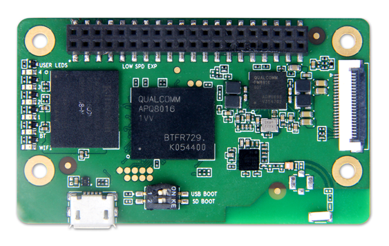
Developer Board 4IoT
Geniatech’s Developer Board 4IoT, features a Qualcomm Snapdragon 410E processor, a Quadcore ARM® Cortex™ A53 at up to 1.2GHz clock speed per core, capable of 32-bit and 64-bit operation. It supports Android, Linux and Windows 10 IoT Core and offers advanced processing power, WLAN, Bluetooth, and GPS. It supports feature-rich functionality, including multimedia, with the Adreno™ 306 GPU, integrated ISP with up to 13 MP camera support, and 1080p HD video playback and capture with H.264 (AVC). The 60 x 35mm SBC integrates the “Standard Micro” IE format’s 40-pin low-speed expansion connector, which is required on the “Extended” format, rather than the 30-pin subset used on MCU-based IE boards such as Seeed’s Carbon. The 4IoT is also equipped with a microSD slot, a micro-USB port for power, 6x LEDs, 2-lane MIPI-CSI, and -25 to 85°C support.
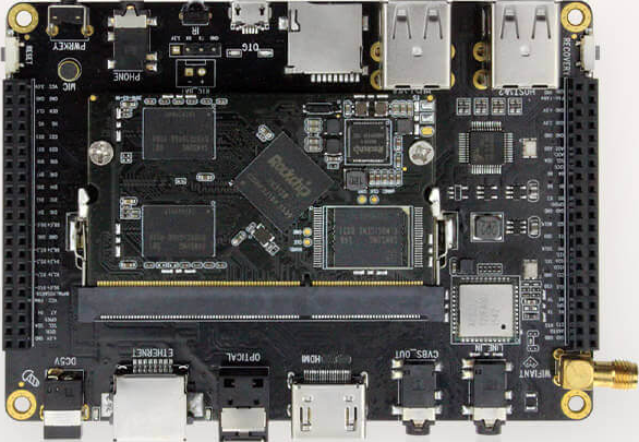
Firefly-RK3128
T-Firefly’s Firefly-RK3128 SBC, dual boots Android 5.1 and Ubuntu 15.04 on a quad-core -A7 Rockchip. The board device includes GbE, WiFi, BT, HDMI, MIPI-DSI, MIPI-CSI, SPDIF, analog audio, LVDS, IR, and CVBS. The 117 x 85mm SBC is further equipped with 4x USB host ports, a micro-USB OTG port, and dual 42-pin expansion connectors. It features ARM Mail-400MP2, a build-in dedicated 2D processor, supports OpenGL ES1.1/2.0, achieves 1080P H.265 hardware decoding, and 1080P H.264 video encoding.
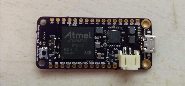
Giant Board
The Giant Board is a super tiny single-board computer based on the Adafruit Feather form factor. The 51 x 23mm SBC from Groboards runs Debian with mainline Linux kernel 5.0 on a Microchip SAMA5D27. The SoC enables Microchip’s ATSAMA5D27C-D1 System-In-Package (SiP), which features 128MB RAM. The Giant Board can load stackable FeatherWing modules from a list of 60+, including Ethernet and LCD add-ons. I/O includes 6x ADC, 4x PWM, I2C, SPI, UART, and I2S. The SBC also features 3.7V LiPo battery support.
HummingBoard Gate
The HummingBoard Gate is designed primarily for IoT solutions, and it is based on NXP’s i.MX6 series. The SBC is almost identical to the HummingBoard Edge, and offers the same 102 x 69mm footprint, 7-36V power supply, mini-PCIe slot, and optional wireless modules and metal enclosure. It features a MikroBus socket that enables MikroElektronika’s 200-plus Click add-on I/O and sensor modules. It also offers multiple temperature ranges.
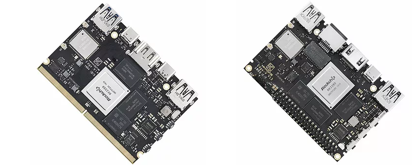
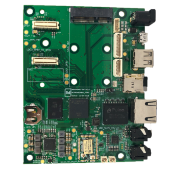
Khadas Edge / Edge-V
The Khadas Edge was announced along with a similar Edge-V model and an RK3399Pro based Edge-1S. The Edge features an MXM3 connector for deploying the board like a compute module on a cluster or carrier board such as the Captain. It also offers FPC connectors for hooking up options like the Edge IO serial debug and GPIO board. The Edge-V also features a Khadas Vim-like 40-pin RPi connector and a GbE port, microSD, and M.2 2280 with NVMe support. Additional features of the Edge-V includes MIPI-CSI and -DSI, eDP 1.3, touch support, RTC, IR, gesture sensor, and 6-axis IMU. The Edge models feature single USB 3.0 and 2.0 ports, 4K-ready DP and HDMI 2.0a, and a DisplayPort via one of the two USB Type-C ports. The Basic model (2GB/16GB) features dual-band WiFi-ac and BT 4.1, while the Pro and Max feature Bluetooth 5.0, and add RSDB WiFi. They offer support for Android Oreo, Ubuntu 18.04, Debian 9.0, and more.
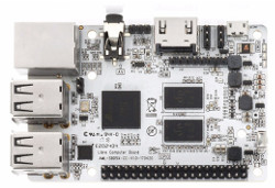
Libre Computer Board AML-S905X-CC (Le Potato)
Also known as Le Potato, the Raspberry Pi-like Libre Computer Board AML-S905X-CC is equipped with the quad -A53 S905X SoC, and features 4x USB host ports, fast Ethernet, and 40-pin expansion. Available also is optional eMMC, IR, and an ADC + I2S header. It also features a v2.0 with 4K HDMI port. The board comes with schematics and source code for Linux 4.14 LTS, Buildroot with Linux 4.9, Armbian Debian and Ubuntu, LibreELEC 9, and Android builds up 8.0 (Oreo).
Nitrogen8M_Mini
The 114.3 x 88.9mm Nitrogen8M_Mini board features NXP’s i.MX8M Mini, and offers a host of pre-certified WiFi-ac/BT with or without a dev kit, a 5V power supply, an 8GB microSD card with Linux, a battery, and a serial console cable. The Nitrogen8M_Mini board also enables a GbE port with optional PoE, USB 2.0 host, and a micro-USB OTG port. Available also is MIPI-DSI and -CSI. Other features include dual audio jacks, a PCIe slot, an RTC, a PMIC, and a choice of 0 to 70°C or -40 to 85°C ranges. OS support includes Linux 4.9x, Yocto, Ubuntu 18.04, Debian Buster 10, and Android 9.