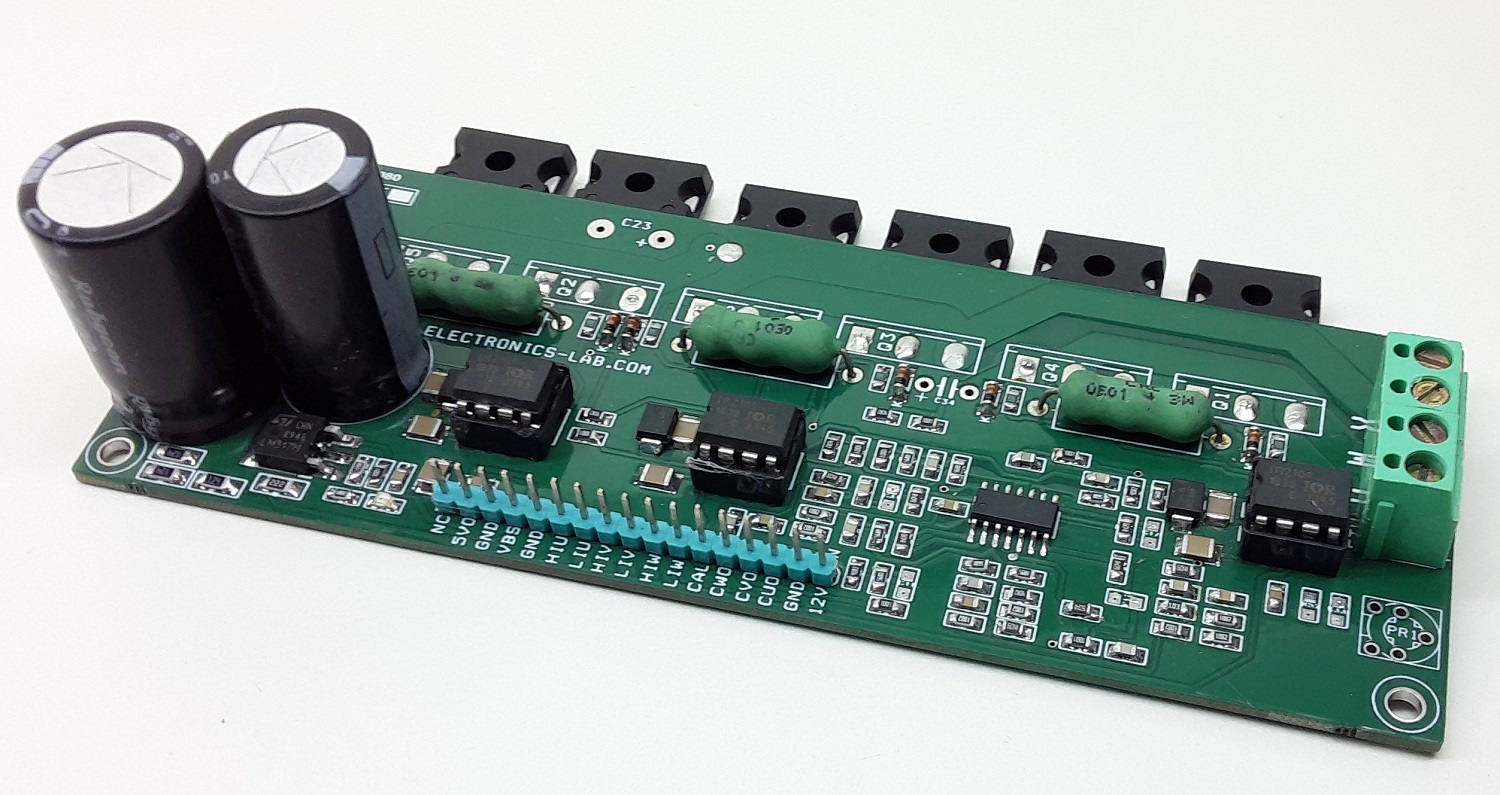
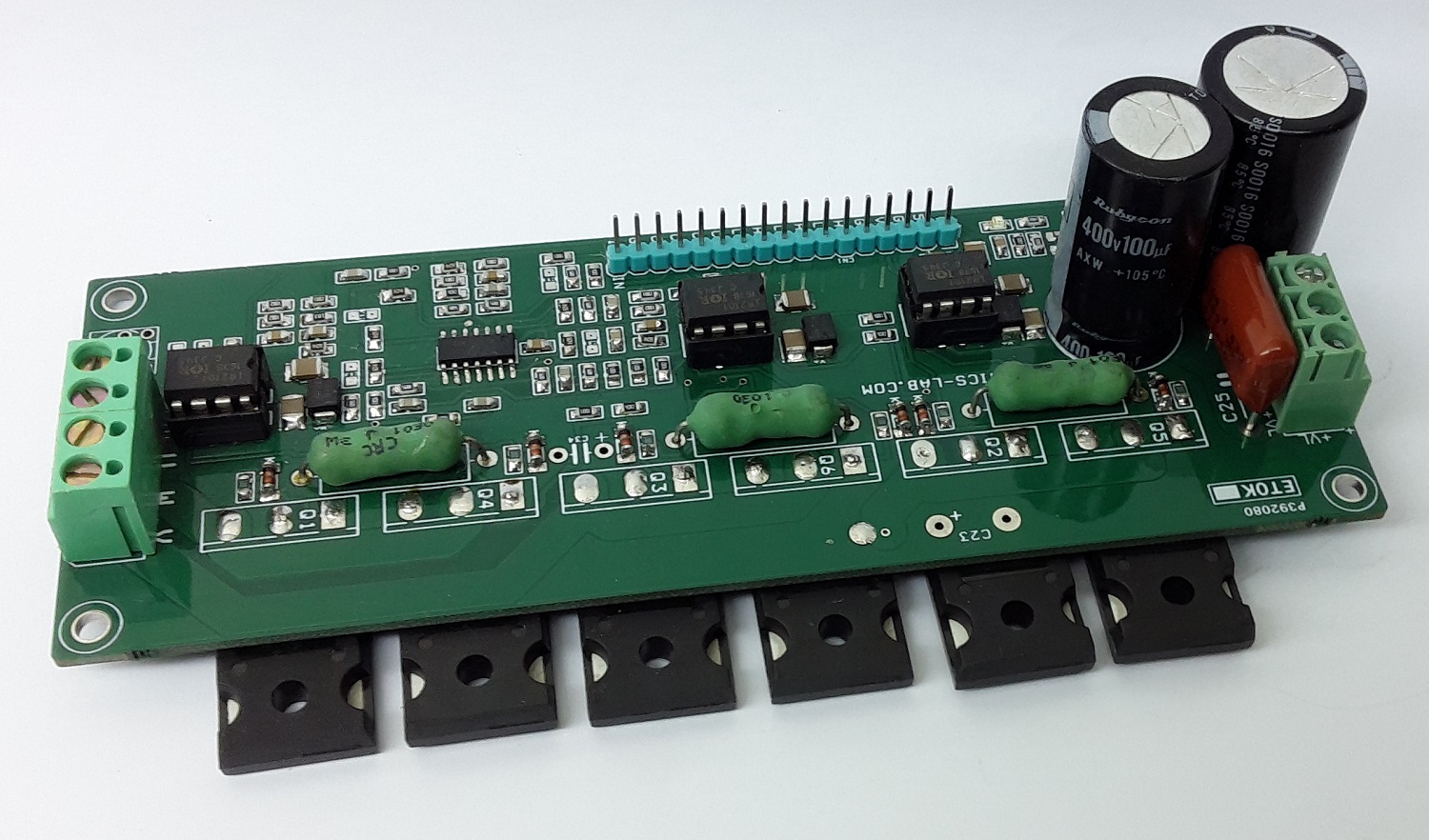
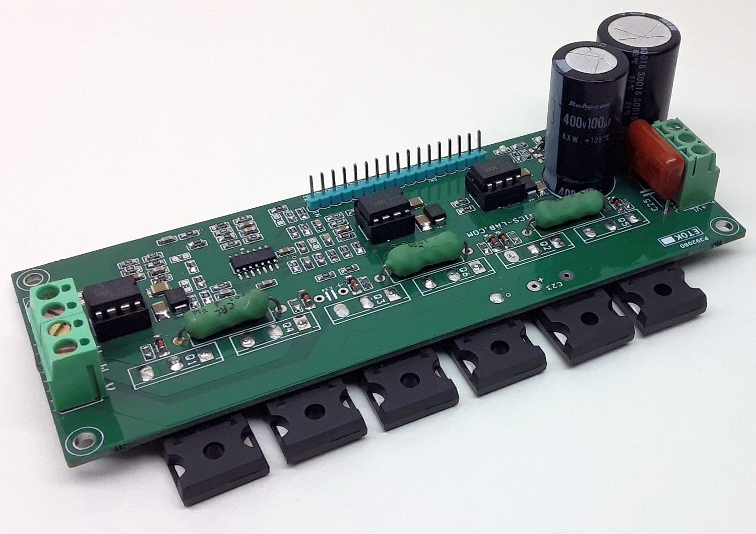
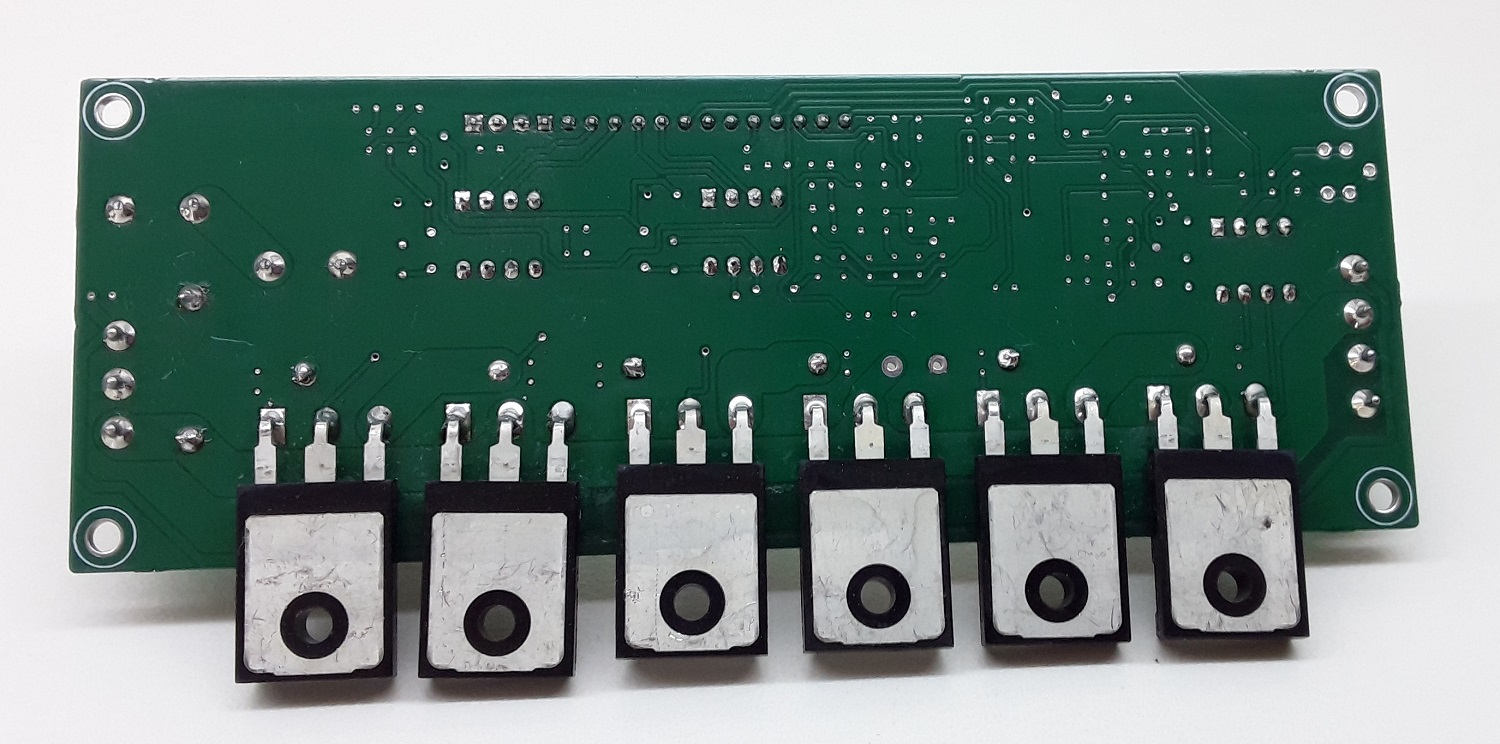
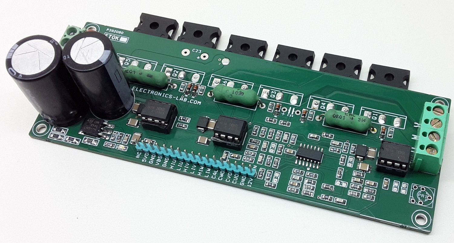
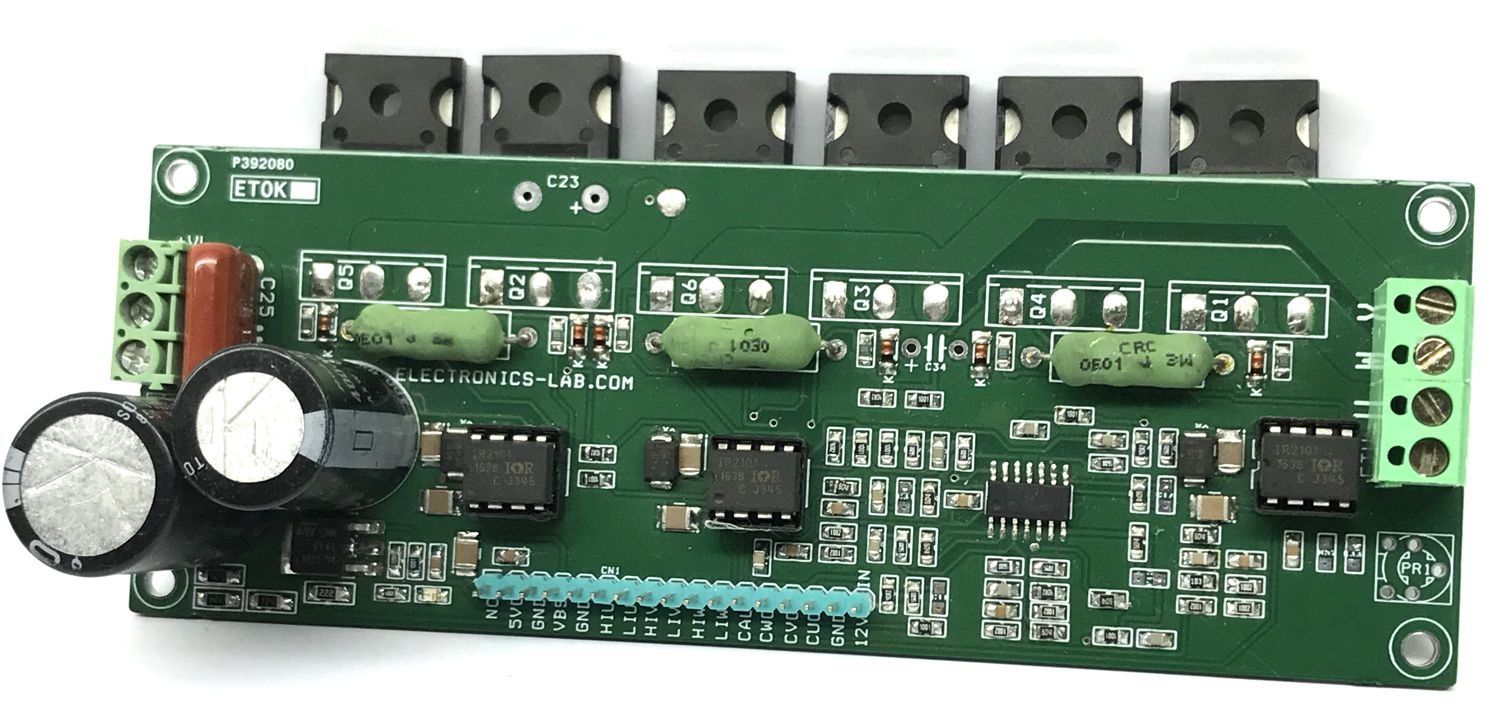
The project presented here is a three-phaseBLDC motor pre-driver. The project consists of 3x half-bridge IR2101 driver IC and 6 channel high current N-MOSFETS. The project can be configured as 3 independent half-bridges H-bridge for a brushed DC motor, or a single high current brushless motor driver. The rotor position can be detected using 3 hall sensors assembled in the motor. Hall-effect shaft position sensors are used to control the switching sequence of the three 1/2 bridge outputs. The bridge voltage can vary between 15V and 60V and the maximum summed bridge current is 10A with a large size heat-sink and sufficient airflow using a fan. This motor driver can be used for multiple applications including e-bikes, battery-powered tools, electric power steering, wheelchairs, or any other application, where a BLDC motor is utilized
15V to 60V – Three-Phase Brushless DC Motor Pre-Driver – [Link]
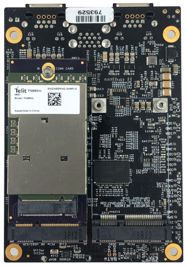
5G is the latest technology in the cellular communication space, offering faster speeds, lower latency, and enhanced capacity. 5G modems for embedded applications are largely being released in the M.2 form factor. Gateworks single board computers use Mini-PCIe slots for cellular and WiFi connectivity.
To accommodate these new 5G modems, Gateworks has released a flexible Mini-PCIe to M.2 adapter that supports modems up to 52mm in length. The M.2 slot is a B-Key slot that supports USB 2.0 & 3.0 depending on the model, with PCIe signalling optional. Dual Nano SIM slots are available on the backside of the card.
Telit 5G Modem using M.2 Adapter on Mini-PCIe slot on Gateworks GW6200 SBC
5G M.2 Cellular Modem Adapter Highlights:
Converts Mini-PCIe slot to M.2 B-Key Slot
Supports various size M.2 Cards30, 42, 50 & 52mm long 5G M.2 Modems (30mm wide & less)
Offers Dual Nano SIM slots
Supports both USB 2.0 and 3.0 (varies by model)
PCIe can optionally be supported at the time of order
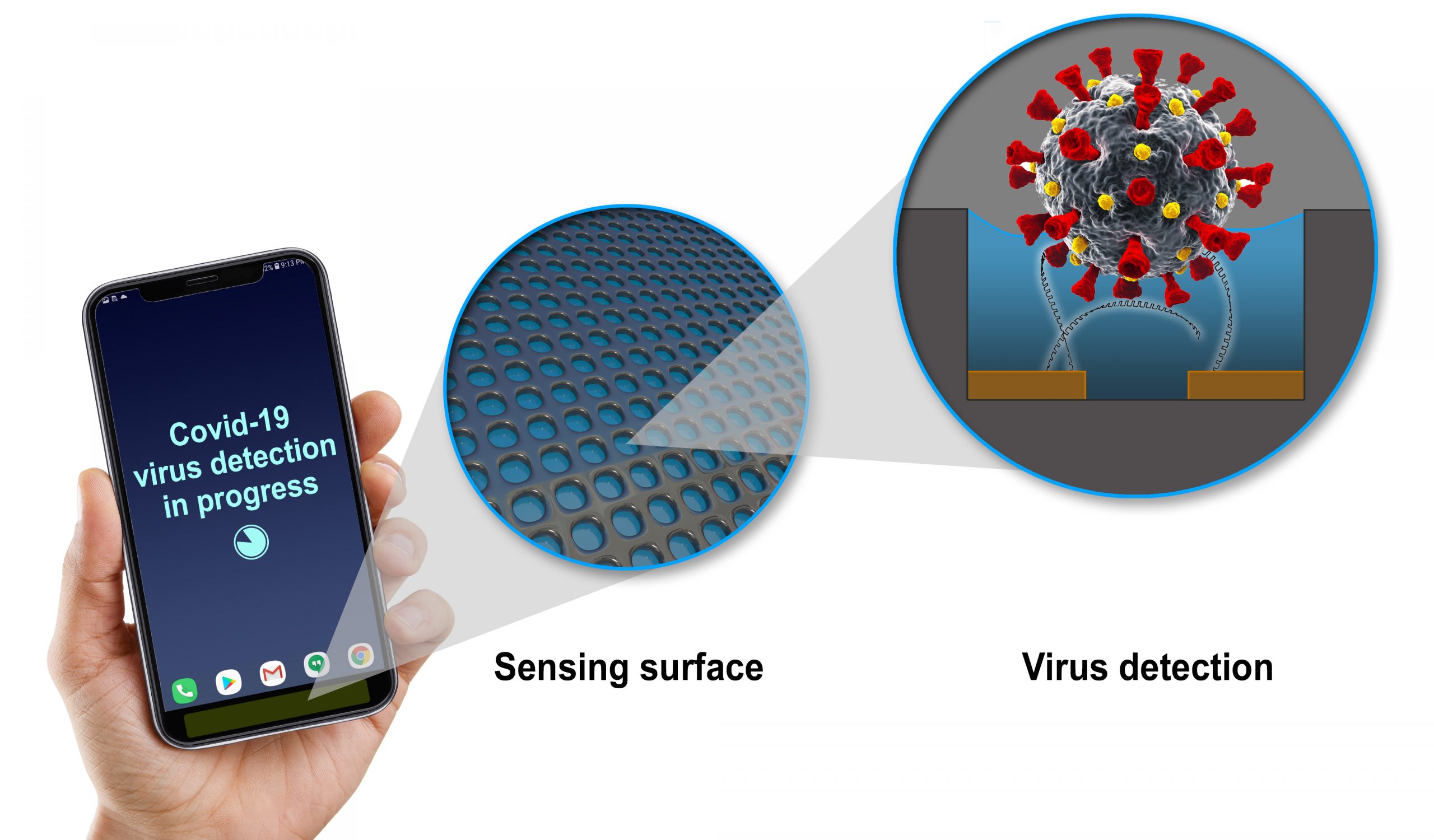
A promising technology is arising in GE’s research labs. by Daniel Kruger & Dorothy Pomerantz @ ge.com
GE researchers are working on a sensor smaller than a fingertip that could find viruses and pathogens in the air. Led by Radislav Potyrailo, a principal scientist at GE Research in Niskayuna, New York, the team received a two-year research grant from the National Institutes of Health to build the tiny device.
The finished project will produce a microchip smaller than a dime with nanowells, or tiny pores, that can only be activated by a particular molecule — in this case, a molecule from the coronavirus causing COVID-19. “In each of those nanowells there are bioreceptors that are designed to recognize only the virus particle they were designed for,” Potyrailo says. “If some flu particle or pollen or bacterium appears, it won’t be recognized. It’s like a lock and key.”
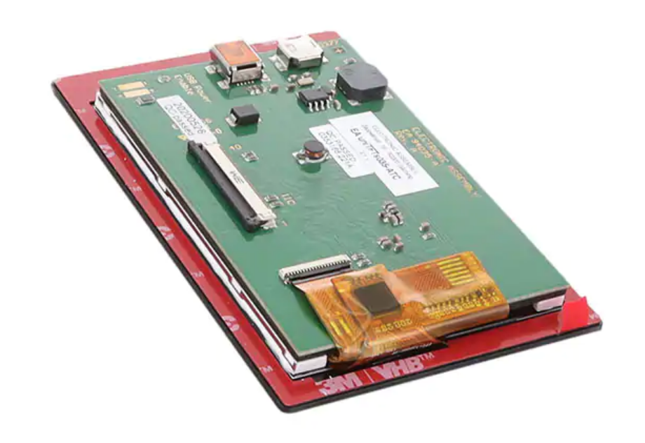
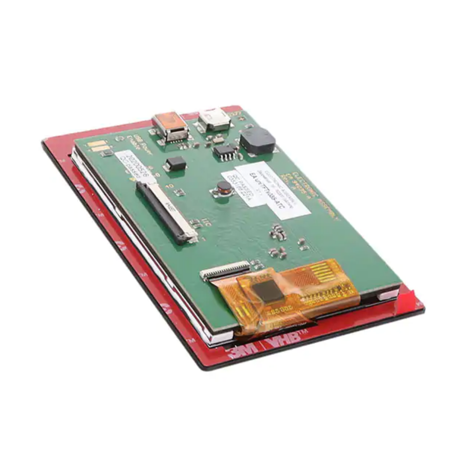
Display Visions’ 3.5″ intelligent IPS TFT display module includes graphics development software
EA Display Visions’ 3.5″ intelligent EA uniTFTs035-ATC display module is an all-in-one implementation of the display, microcontroller unit, and touchscreen. The module includes everything needed to directly control an application and expedite the development, prototyping, and deployment of an HMI/GUI. Design an HMI/GUI using the easy-to-use drag-and-drop uniTFT DESIGNER graphics development software and simple ASCII text-based instructions. Thanks to the integrated input/output and fast graphics controller, the display modules are ready to run without additional peripherals. They can be controlled via USB, SPI, I²C, and RS232. The IPS panels with all-angle color stability (AACS) technology keep contrast and colors stable even at oblique viewing angles. These displays are not subject to the inverse tilt effect that is inherent in the widely used TN displays. With a maximum brightness of more than 1,000 cd/m², they are readable even in direct sunlight or under bright surgical lights. The capacitive touch surface of the uniTFT recognizes multi-finger gestures and reacts reliably when used with thin gloves.
Tagore’s transistor is ideal for radio applications such as public safety radios and EW radios.
Tagore’s TA9410E is a broadband 50 V, 25 W GaN transistor capable of operating from 20 M to 3 GHz. Using a simple input/output match, it can be tuned for various bands of interest. This transistor can be considered as a final stage PA or driver.
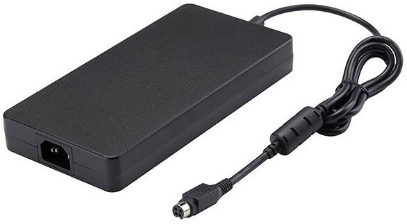
SP’s FSP330 is a slim 330 W high wattage fanless external power supply
The FSP330 is a 330 W AC-to-DC adapter from FSP intended for use in IPC systems, embedded systems, printers, monitors, charging systems, and POS systems that have high wattage demands. This adapter operates at 90 VAC to 264 VAC input voltage and meets CISPR32 EN55032 CLASS B, EN55024, and FCC PART 15B Class B emission limits, and is designed for ITE application.
The Würth Elektronik sensors are an integral part of every future application. Measuring temperature, humidity, pressure or acceleration has never been easier. Take advantage of services like the Software Development Kit and Evaluation Boards available off-the-shelf. Detailed documentation, as well as direct support by trained engineers, will leave no questions open.
With excellent measuring accuracy and long-term stability, the sensors provide high precision and accurate output values with intelligent on-chip interrupt functions.
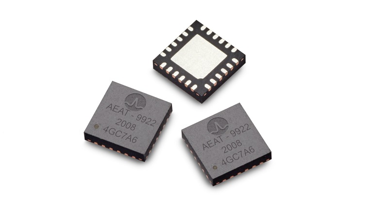
The AEAT-9922 is an angular magnetic rotary sensor that provides accurate angular measurement over a full 360° of rotation
The AEAT-9922 is an angular magnetic rotary sensor that provides accurate angular measurement over a full 360° of rotation. It is a sophisticated system that uses integrated Hall sensor elements with complex analog and digital signal processing within a single device. A simple two-pole magnet generates the necessary magnetic field by rotating it perpendicularly. Wide magnetic field sensor configurations allow on-axis (end of shaft) or off-axis (side of the shaft) modes. The AEAT-9922 is a versatile solution that supports a broad range of applications with its robust architecture to measure and deliver both absolute and incremental signals.
Key features
5 V and 3.3 V operation
Selectable 10 bits up to 18 bits of absolute resolution
Flexible Incremental ABI resolution ranging from 1 to 10,000 CPR
Commutation angle output UVW 1 to 32 pole-pair
Additional features
PWM output modes with Cyclic Redundancy Check (CRC)
User-programmable zero position, direction, index width, and index position
Programmable hysteresis
Absolute output over 2-wire SSI, 3-wire SSI, and 4-wire SPI
The diode is a semiconductor device that allows current to flow in only one direction when it is forward biased and blocks the current in reverse bias condition. This has been explained in the previous article of “The Signal Diode”. This feature of the diode resembles a switch or valve and can be utilized to allow passage of current at certain desired conditions only.
In the “The Signal Diode” article, the most popular applications of diodes have been explained and one of them is Rectification. The Rectification means, in electrical terms, conversion of alternating current (AC) to direct current (DC) using electronic equipment. The alternating current is bidirectional, having positive and negative values, and the direct current is unidirectional, either positive or negative. The direct current signal should ideally provide a continuous and constant value. The rectifier circuits are mostly used in power supplies, inverters, and battery chargers, etc. The diodes used in high-power circuits are termed Power Diodes.
Power Diode
The power diode has the capability to pass high current through it and can withstand high voltage. It has a larger PN-junction compared to the simple diode and as such can allow several hundred amperes to flow through it. However, the larger PN-junction of the power diode, makes it less responsive to high-frequency signals. Commercially available power diodes are used in battery chargers, inverters, and rectifiers, etc. Due to their high voltage withstand capability they are used as freewheeling diodes to protect against voltage spikes/ surges.
The power diodes have a greater breakdown voltage and are generally classified into:
General Purpose
Fast Recovery
Schottky
The general purpose power diodes are the most commonly used in electronic circuits involving power supplies and rectifiers. The Glass Passivated type 1N400X (1N4001 to 1N4007) series of power diodes have voltage rating from 50 V to nearly 1000 V with a forward current bearing capacity of 1A at these voltages.
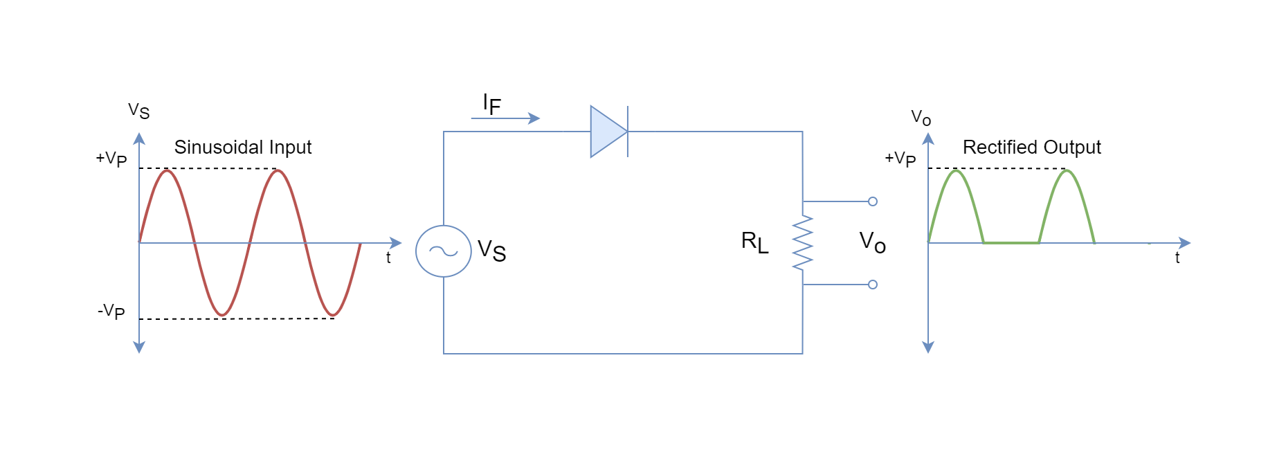
A simple power diode rectifier circuit is shown in the following figure. This is the simplest example of the rectifier and termed a half-wave rectifier which is explained below in the article.
Figure 1: A simple half-wave power rectifier.
The half-wave rectifier has a sinusoidal input and the power diode conducts (ON) only during the positive (+) cycle (half of the full-cycle) when the anode is more positive with respect to the cathode. In the next half-cycle (negative one), the power diode blocks (OFF) the current until the next positive half-cycle. The voltage appears across the load resistance during the ON period only. The input sinusoidal wave has been clipped off during the negative half-cycles and only positive half-cycles appear across the output. The rectification during only half-cycles terms the circuit as a half-wave rectifier.
In addition to positive cycle rectification, the diodes can be used to rectify during full-cycle and are called “Full-Wave” or “Bridge” rectifiers.
Rectifiers
The rectifiers based solely on diodes are uncontrolled rectifiers in which the output cannot be controlled and remains constant. The rectifiers based on Silicon-Controlled Rectifiers (SCR) are controllable rectifiers and the output of rectifiers can be controlled through firing angles of SCRs.
Half-Wave Power Rectifier Circuit
Continuing with the above half-wave power rectifier circuit, a half-wave rectifier circuit for conversion of mains supply (230 VACRMS) to 10 VDC is explained for understanding. Before, the basic calculations are revised to cope up with the upcoming explanation of the half-wave rectifier circuit.
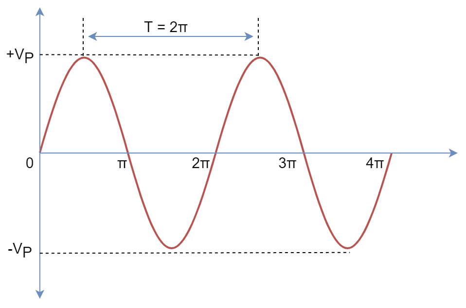
Figure 2: A Sinusoidal Wave signal.
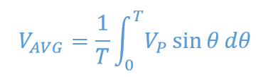
The average value of the periodic signal is given below:
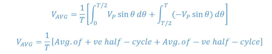
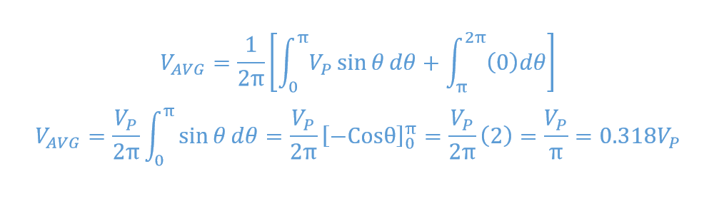
For a sinusoidal signal, the positive half-cycles equals negative half-cycles, and such cancels out to zero average. For a half-wave rectifier, the average is given as follow:
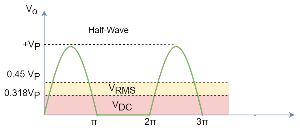
Figure 3: Half-Rectified Sinusoidal wave.
The half-rectified figure shows, Time Period = 2π and no (zero) signal during the negative (-) half-cycle, resulting in:
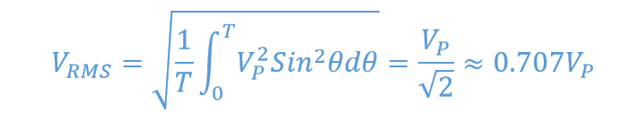
Similarly, the root means square (RMS) represents the DC equivalent of an AC signal for power calculations and calculated as:
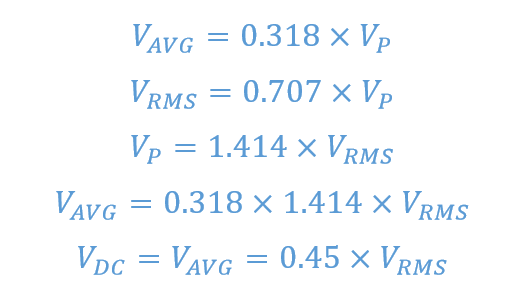
In a nutshell, for a half-wave rectifier:
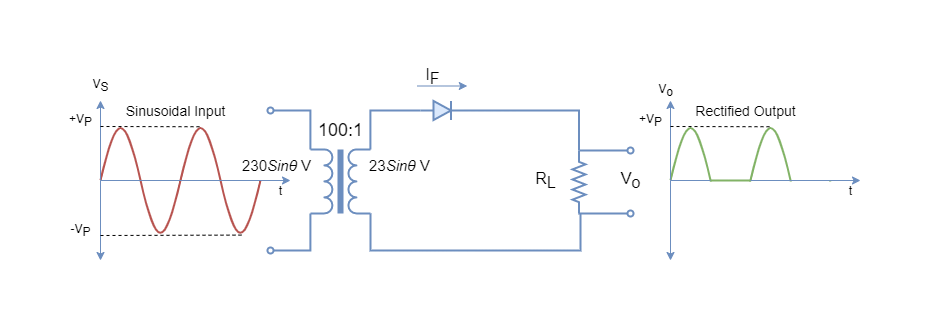
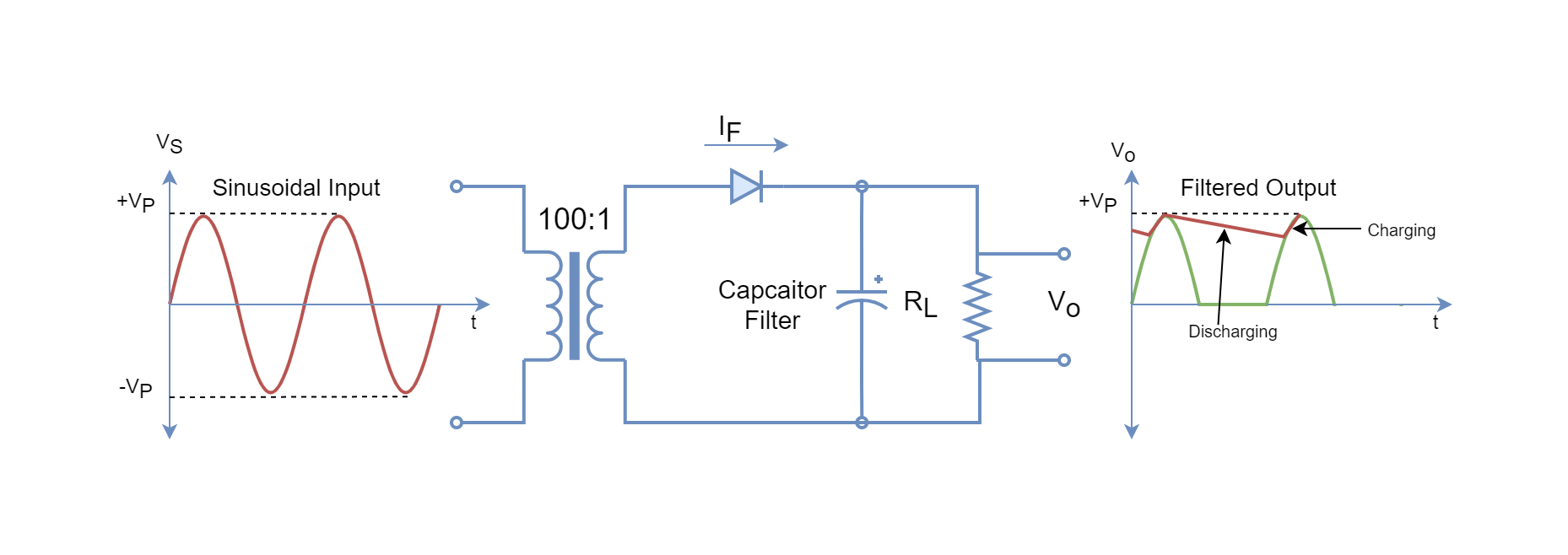
Now, consider the following half-wave rectifier circuit in which a transformer (100:1) is used to step down the mains supply from 230VAC to 23VAC.
Figure 4: A typical half-wave power rectifier example.
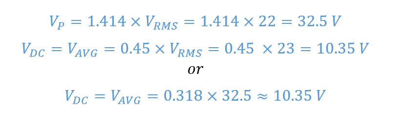
Using the above formulas on the secondary side of this circuit:
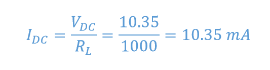
So, a 10VDC appears across the 1 kΩ load. The average current flowing through the load:
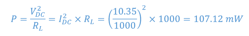
For power dissipation, the following formula can be used on the supposition that it is purely a DC signal.
In half-wave rectifiers, only 50% of the input signal is converted into a DC signal, and the rest of the 50% is wasted due to the OFF state of the rectifier. Due to this, the less average value is delivered to the load and the circuit is not that efficient. Further to this, the half-wave rectifier is prone to ripples due to a larger stop period and frequent switching. The ripples cause fluctuations and are undesired in electronic and digital circuits. The ripples cause unnecessary heating, distortion, and noise etc. Especially, in digital circuits, it may cause malfunctioning and give undesired output.
The ripples can be primarily avoided using a shunt capacitor and called filter capacitor or smoothing capacitor because of its purpose in the circuit. A half-wave rectifier circuit with a capacitor filter is shown in the following figure. The circuit is called a peak rectifier.
Figure 5: A Half-Wave power rectifier with capacitor filter.
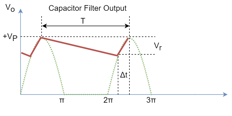
The capacitor acts as a storage or reservoir and supplies the load during the OFF period. The value of the capacitor should be large enough so that its time constant (RC) >> time period of the sinusoidal signal. The capacitor gets charged to peak voltage on the initial positive cycle and when the negative cycle starts, the diode cuts off supply to the capacitor. The diode supplies the load and charges the capacitor during the (Δt) period. For the rest of the period, the capacitor supplies the load current until input voltage becomes equal to capacitor decaying voltage during the next positive cycle. The capacitor recharge starts and the process keeps repeating.
Figure 6: Output half-wave after usage of capacitor filter.
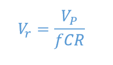
The ripple voltage for a half-wave rectifier is given by the following formula:
The half-wave rectifiers are seldom used because of their low average output and half of the input cycle is not utilized. They can be found in low-power or cheap power supplies. Instead, the full-wave or bridge rectifier is used because of its high average output and utilizes both input cycles.
Conclusion
The power diode is used for applications involving high current and high voltage.
Power diodes have a larger PN-junction and, thus, have greater breakdown voltage.
Power diodes are less responsive to high-frequency signals such as greater than 1 MHz signals.
Power diodes are used in power supplies, battery chargers, rectifiers, and inverters, etc.
The rectifier converts alternating current into direct current.
The half-wave rectifier uses a single power diode to convert the half-cycle of the input cycle.
The average or DC output of the half-wave rectifier is VDC = 0.318XVP or 0.45XVRMS.
The half-wave rectifier DC output is low compared to the input, half-cycle of input goes unutilized and is prone to ripples.
The ripples can be reduced by the use of a capacitor filter across the load and called a peak rectifier.
The capacitor should be large enough to have a greater time constant (RC) than the time period of the input signal.
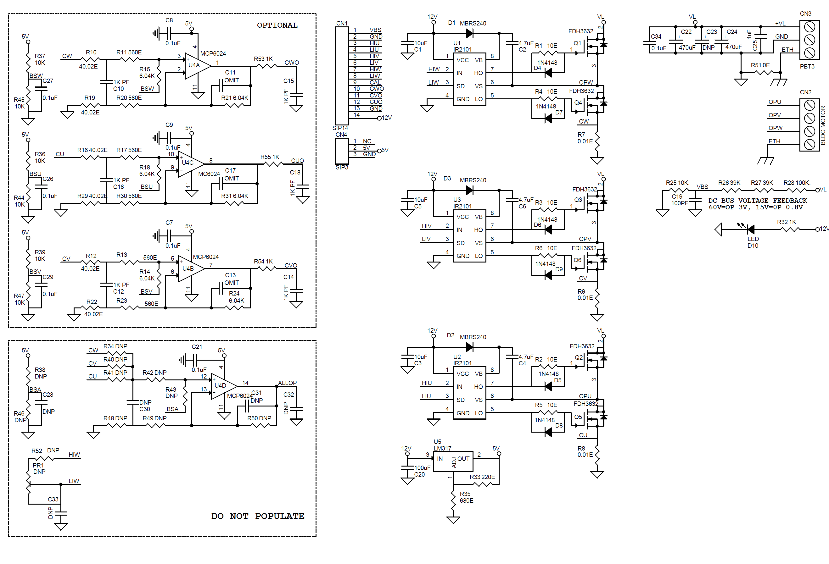
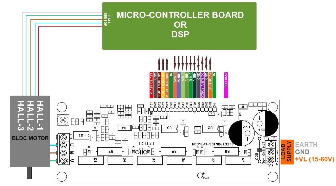
The project presented here is a three-phaseBLDC motor pre-driver. The project consists of 3x half-bridge IR2101 driver IC and 6 channel high current N-MOSFETS. The project can be configured as 3 independent half-bridges H-bridge for a brushed DC motor, or a single high current brushless motor driver. The rotor position can be detected using 3 hall sensors assembled in the motor. Hall-effect shaft position sensors are used to control the switching sequence of the three 1/2 bridge outputs. The bridge voltage can vary between 15V and 60V and the maximum summed bridge current is 10A with a large size heat-sink and sufficient airflow using a fan. This motor driver can be used for multiple applications including e-bikes, battery-powered tools, electric power steering, wheelchairs, or any other application, where a BLDC motor is utilized. Motor start/stop, forward/reverse rotation, braking with closed-loop speed control. The project also includes 3 phase current sense circuit which can be used to detect 3 independent phase currents. An LM317 regulator provides 5V DC to op-amp circuitry. All inputs and feedback outputs provided for an easy micro-controller or DSP interface.
Current Sense Circuit: Current sense circuit measures the current across all 3 half-bridges and provides 3 independent current feedback outputs, this can be used for overcurrent sense or senseless FOC configuration, the default output at 0A is 1.45V, and provides approx. 100mV/Amp. User may change the Gain of an op-amp, current shunt resistors as per requirement, LM317 power 5V to op-amp circuit.
User need to generate 6 PWM pulse sequence to control the motor, the board accepts TTL input, more information about brushless motor driver available here: