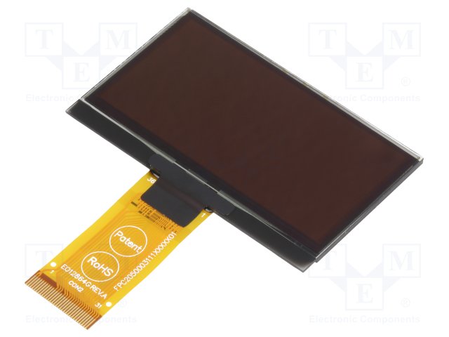
Display Visions’ 0.84″ 96 x 16 OLED display is ideal for small, compact low-power applications
Display Visions’ yellow OLEDs come packaged as a complete module that includes all required logic at only a 1.34 mm thickness. With a built-in controller, 2000:1 contrast ratio, 10 µs response time, viewing angles greater than 160°, and the ability to withstand harsh environments due to its extreme temperature range of -40°C to +80°C, these displays will offer any industry an upgrade to their current monochromatic character application.
All OLED displays can be evaluated using the EA 9781-USB evaluation board, and a free simulator tool can be downloaded to start the design process.
Features
0.84″ low-power OLED (15 mA typ.)
Temperature range: -40°C to +80°C
96 x 16 dots
Bright white content with unlimited viewing angle
Includes SSD1306B controller
EA W096016-XALW: I²C-Bus interface
EA W096016-XBLW: I²C-Bus and SPI interface (3- and 4-wire)
Fast response time (10 µs) even at -40°C
Connection by stamp soldering or ZIFF connector
RoHS, CE, and REACH compliant
Applications
IoT systems
Low-power handheld devices
Oil and gas equipment
Laboratory equipment
Industrial controls, instrumentation, and machines
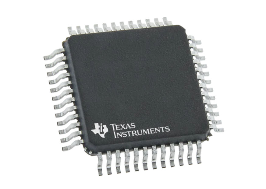
Texas Instruments’ high-accuracy protector is designed for Li-Ion, Li-Polymer, and LiFePO4 battery packs
Texas Instruments’ BQ76952 device is a highly integrated, high-accuracy battery monitor and protector for 3-series to 16-series Li-Ion, Li-Polymer, and LiFePO4 battery packs. The device includes a high-accuracy monitoring system, a highly configurable protection subsystem, and support for autonomous or host-controlled cell balancing. Integration includes high-side charge-pump NFET drivers, dual-programmable LDOs for external system use, and a host communication peripheral supporting 400 kHz I2C, SPI, and HDQ one-wire standards. The BQ76952 device is available in a 48-pin TQFP package.
Features
Battery monitoring capability for 3-series to 16-series cells
Integrated charge pump for high-side NFET protection with optional autonomous recovery
Extensive protection suite including voltage, temperature, current, and internal diagnostics
Two independent ADCs:
Supports simultaneous current and voltage sampling
High-accuracy coulomb counter with input offset error <1 µV (typ.)
High-accuracy cell voltage measurement <10 mV (typ.)
Wide-range current applications (±200 mV measurement range across the sense resistor)
Integrated secondary chemical fuse drive protection
Autonomous or host-controlled cell balancing
Multiple power modes (typical battery pack operating range conditions):
NORMAL mode: 286 µA
Multiple SLEEP mode options: 24 µA to 41 µA
Multiple DEEPSLEEP mode options: 9 µA to 10 µA
SHUTDOWN mode: 1 µA
High voltage tolerance of 85 V on cell connect and select additional pins
Tolerant of random cell attach sequence on the production line
Supports temperature sensing using an internal sensor and up to nine external thermistors
Integrated one-time-programmable (OTP) memory programmable by customers on the production line
Communication options: 400 kHz I2C, SPI, and HDQ one-wire interface
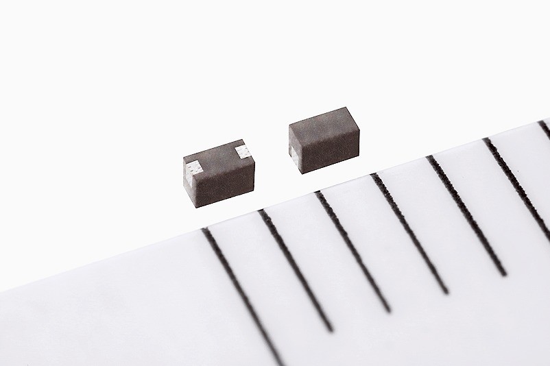
TDK Corporation’s inductors are available in a compact external size and an impressive rated current
TDK Corporation has developed the PLEA67 series of inductors for use in true wireless stereo (TWS) devices. TWS devices are finding increasing applications with smartphones, smartwatches, and other wearables and in turn, the demand for electronic components in this domain is rising.
This series of inductors is intended for use in power circuits incorporated into wireless earphones used with smartphones, portable players, and similar devices. In addition to an impressive rated current of 500 mA, the PLEA67 series of inductors also boasts one of the industry’s smallest external sizes, measuring at 1.0 mm (L) x 0.6 mm (W) x 0.7 mm (H), respectively. The compact external size facilitates space savings in circuit board design and helps reduce the weight of earphones, providing users with mobility comfort. The magnetic shield structure reduces magnetic flux leakage to pave the way for high-density implementation. TDK’s original structure design and more recently developed materials are used in its thin-film process to achieve a rated current of 500 mA, despite a high inductance of 2.2 µH for its size.
Compact size
Rated current of 500 mA
Flux leakage reduction structure opening the way for high-density implementation
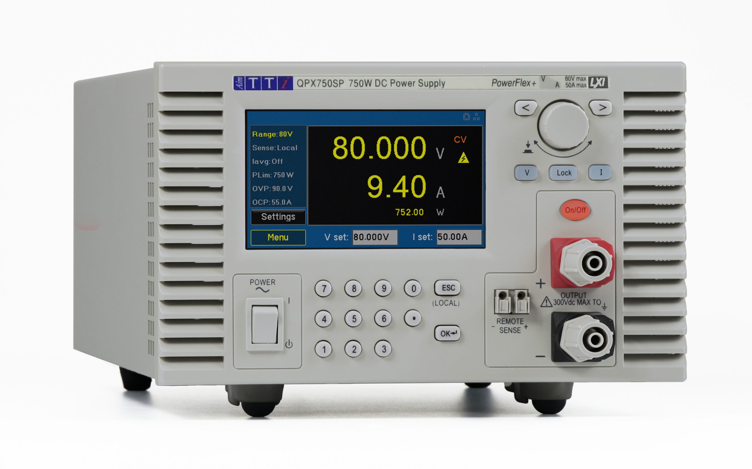
The Aim-TTi QPX750SP is the first of a new Bench/System Single Output PowerFlex+ DC Power Supply platform. It provides up to 80V or 50A at a maximum of 750W in a benchtop or rackmount housing.
Saelig Company, Inc. announces the availability of the Aim-TTi QPX750SP750W Single Output DC Power Supply that can provide voltages between 80V at 9.4A and 12V at 50A with a maximum resolution of 0.1mV. This laboratory power supply is designed to provide a flexible choice of voltage and current to meet multiple application needs. It is housed in a compact 3U half-rack-width case with front ventilation and low noise fan-assisted cooling. Front and rear power and sense terminals make it suitable for use either on the bench or in a rack-mount system. The available RM460 4U rack kit can accept one or two QPX750SPs with ½U rack spacing above and below to provide full ventilation. The QPX750SP features an SELV mode, an added safety feature where voltages above 50V require authorization from the user. The QPX750SP’s PowerFlex+ design uses a linear final regulation design, which minimizes ripple and improves dynamic performance. This design results in an unusually low noise/power ratio, coupled with good transient response. Three operating modes for the QXP750SP are provided: Constant Voltage, Constant Current or Constant Power, with automatic cross-over dependent on output setting parameters CV, CC or CP mode indication in the display. A 4.3” color touch-screen simplifies operation and enables data entry via touch input in addition to the numeric keypad and rotary encoder. Comprehensive information is displayed for operational settings and limits for voltage, current, or power (watts). Equivalent resistance measurements of the connected load can be made at high currents using the remote sense terminals to create a four-terminal connection. This gives more reliable results for long power leads or components such as magnetics and cable harnesses.
Wide range of voltage/current combinations
Up to 80V and up to 50A within the same power envelope
Low output ripple and noise of <3mV rms at full power
High setting resolution of 1mV
Analog control interfaces for voltage and current
Bench or rack mounting, front and rear terminals
LAN (LXI), USB, (GPIB optional)
A comprehensive array of interfaces including USB, LAN/LXI and quasi-analog are standard, with GPIB available as an option. The QPX750SP is compatible with Aim-TTi Test Bridge software, providing graphical remote instrument control, logging, and sequencing.
Made by Aim-TTi, a leading European test equipment manufacturer, the Aim-TTi QPX750SP750W Single Output DC Power Supply is available now from Saelig Company, Inc., Fairport, NY their technical distributor.
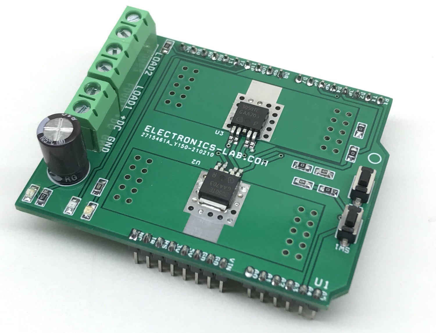
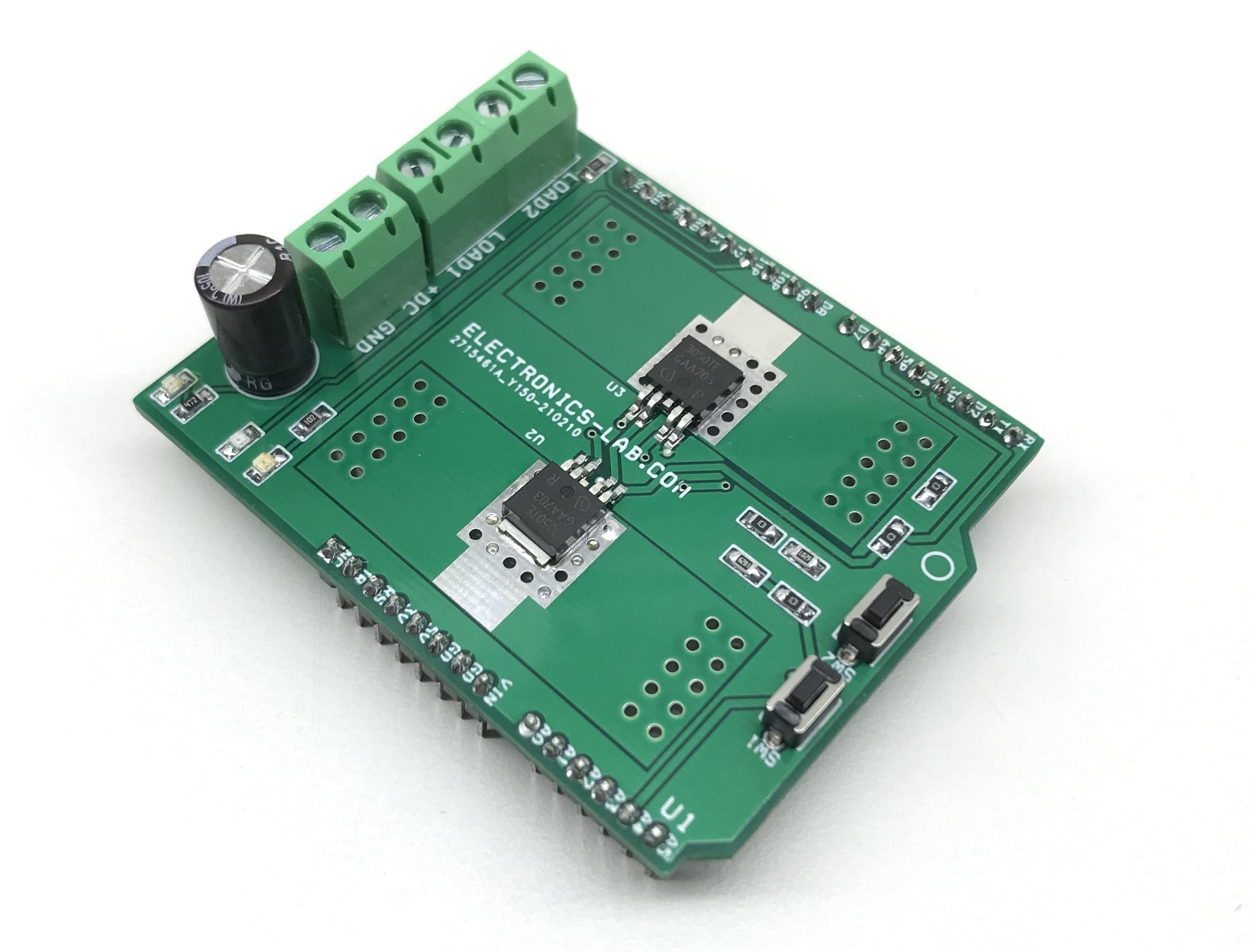
The project presented here enables users to switch all kinds of resistive, inductive and capacitive loads, limited by clamping energy (EAS) and maximum current requirement. The user may interface 2 x inductive, resistive, and capacitive loads such as solenoid, dc motor, high current contact switch, high current relay, LEDs, lamps, and piezo etc. The project is most suitable for inductive loads as well as loads with inrush current. The project has been designed using BTF3050TE IC which is a 50 mΩ single-channel Smart Low-Side Power Switch in a PG-TO252-5 package providing embedded protective functions. The power transistor is built by a N-channel vertical power MOSFET. The device is monolithically integrated. The BTF3050TE is automotive qualified and is optimized for 12V automotive and industrial applications. Two loads can be controlled using Arduino UNO. IC has a thermal-restart function. The device will turn on again, if input is still high, after the measured temperature has dropped below the thermal hysteresis.
In order to optimize electromagnetic emission, the switching speed of the MOSFETs is set to 5 us ON time and 5 us OFF time approx. but this can be adjusted by R6, and R7, refer to the datasheet of the chip for more information. This allows balancing between electromagnetic emissions and power dissipation. Shorting the SRP pin to GND represents the fastest switching speed. Open SRP pin represents the slowest switching speed. It is recommended to put a high ohmic resistor like 200kΩ on this SRP pin to GND. The accuracy of the switching speed adjustment is dependent on the precision of the external resistor used. It’s recommended to use accurate resistors. It is advisable to change capacitor C1 to 470uF if the full load current is in use.
Features
Operates 2 x Loads (Nominal Load Current Each Channel 3A – 6A both)
Maximum on State Resistance 100mOhms Each Channel
Operating Voltage Range 12V-24V for Load ( 3V to 28V Operating Range)
Operating Supply Voltage Range VCC 3 to 5.5V (Connected to 5V of Arduino Uno)
Input Signal Maximum 5.5V
The project can drive Inductive, Resistive, Capacitive Loads
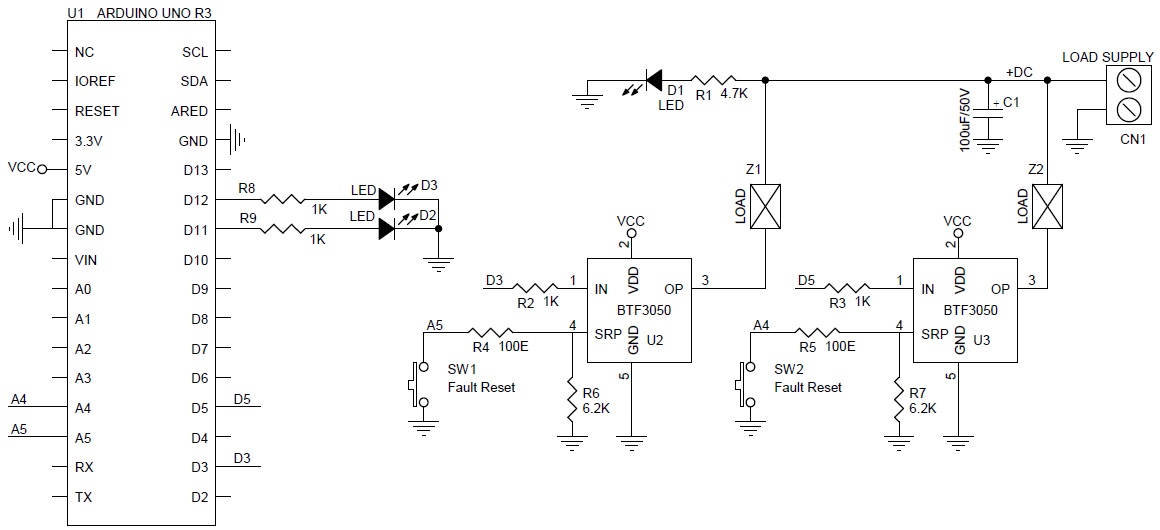
Arduino Digital pin D3 drives Load-1, and D5 drives Load-2
BTF3050TE Input PWM < 20Khz or TTL Input (Arduino D3 and D5)
SW1 and SW2 Resets switch when a Fault condition occurs
Over-temperature shutdown with auto-restart
Active clamp over voltage protection of the output
Enhanced short circuit protection
Active clamp over voltage protection of the output
2 additional LEDs On Arduino D11 and D12 provided for operation indication.
PCB dimensions: 61.91 x 50.64 mm
Testing the board
Arduino Example Code Provided to test the board at the end of the article.
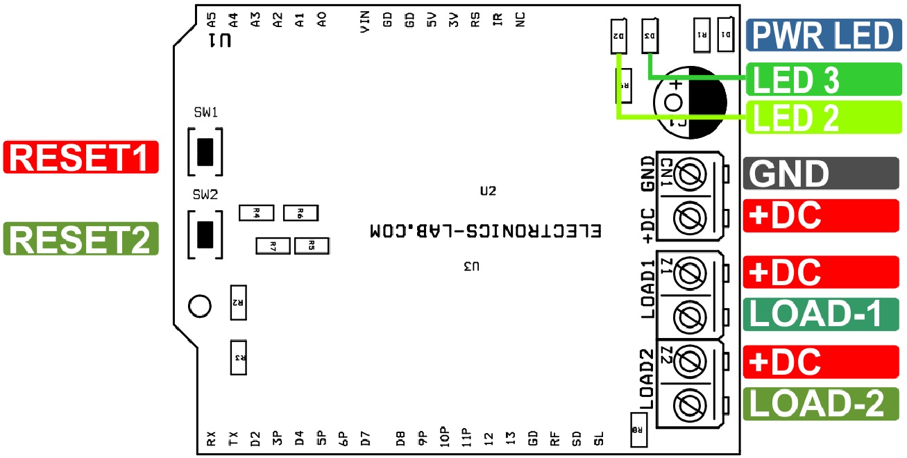
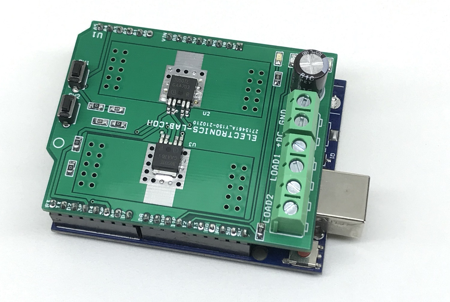
Connect the load at Z1 (Load1) and Z2 connector, Connect the load power supply at CN1, Upload the Arduino code to Arduino UNO, mount the shield on Arduino Uno. Each load will be ON for 1 Second sequentially, at the same time LED D2 and D3 will indicate the operation ON/OFF. Code is determined with ON/OFF operation of loads. Users can write their own code to use PWM and Fault functions.
BTF3050TE Details
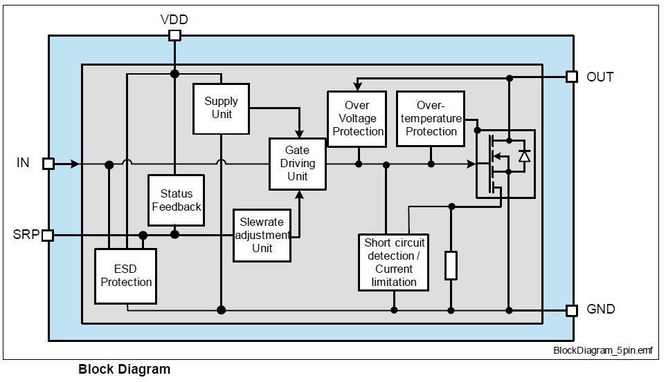
BTF3050TE Block Diagram
Over Voltage and Over Temperature Protection
The over-voltage protection gets activated during inductive turn-off conditions or other overvoltage events (e.g. load dump). The power MOSFET is limiting the drain-source voltage if it rises above the VOUT(CLAMP). The over-temperature protection prevents the device from overheating due to overload and/or bad cooling conditions. The BTF3 has a thermal-restart function. The device will turn on again if the input is still high after the measured temperature has dropped below the thermal hysteresis.
Slew Rate in Fault mode (fault signal set)
Besides the normal slew rate function, the SRP pin is also used as fault feedback output. In case of a latched fault caused by over-temperature detection, the SRP pin will be internally pulled to VCC. For details. In this operation mode (latched fault signal) the slew rate control by RSRP will be ignored and the switching speed (dynamic characteristics) will be set to fault mode default values. As long as the fault signal is set and the SRP-pin is not shorted to GND a fast default slew rate adjustment (like for RSRP R6, R7= 6.2kΩ) will be applied to the device.
Normal operation mode (slew rate mode; low signal)
The pin is used to define the switching speed of the BTF3050TE. A resistor to ground defines the strength of the gate driver stage used to switch the power DMOS. The SRP pin works as a controlled low voltage output with a normal voltage up to VSRP(NOR), driving from VCC a current out of the SRP-pin through the slew rate adjustment resistor. The voltage on the SRP pin in normal operation mode is VSRP(NOR), signaling a low signal to the microcontroller.
Latched Feedback mode (internal pull-up to VCC; high signal)
The pin is used to give alarming feedback to the Arduino after an over-temperature shutdown. The SRP pin is pulled to Vcc by an active internal pull-up source providing typical a current ISRP(FAULT), intended to signal a logic high to the Arduino. This mode stays active independently from the input pin state or internal restarts until it will be reset. During this mode, the slew rate of the device is set to a fast “fault” mode slew rate (similar to the switching times at RSRP = 6.2kΩ.) The latched fault/feedback mode and the signal are available at slew rate resistors of 5kΩ < RSRP < 70kΩ.
The signal diode is a semiconductor device that is based on the PN junction theory, previously described in the article. It is the simplest, non-linear semiconductor device and is found in almost every electronic circuit. As we learned from the previous article, two currents can flow in the PN junction namely diffusion and drift current. The diffusion current is due to majority carriers when the voltage barrier of the depletion layer is overcome. Whilst, the drift current is due to minority carriers and depends on the operating temperature. The signal diode exhibits the flow of both currents and, keeping this in mind, it is good to describe the ideal diode first.
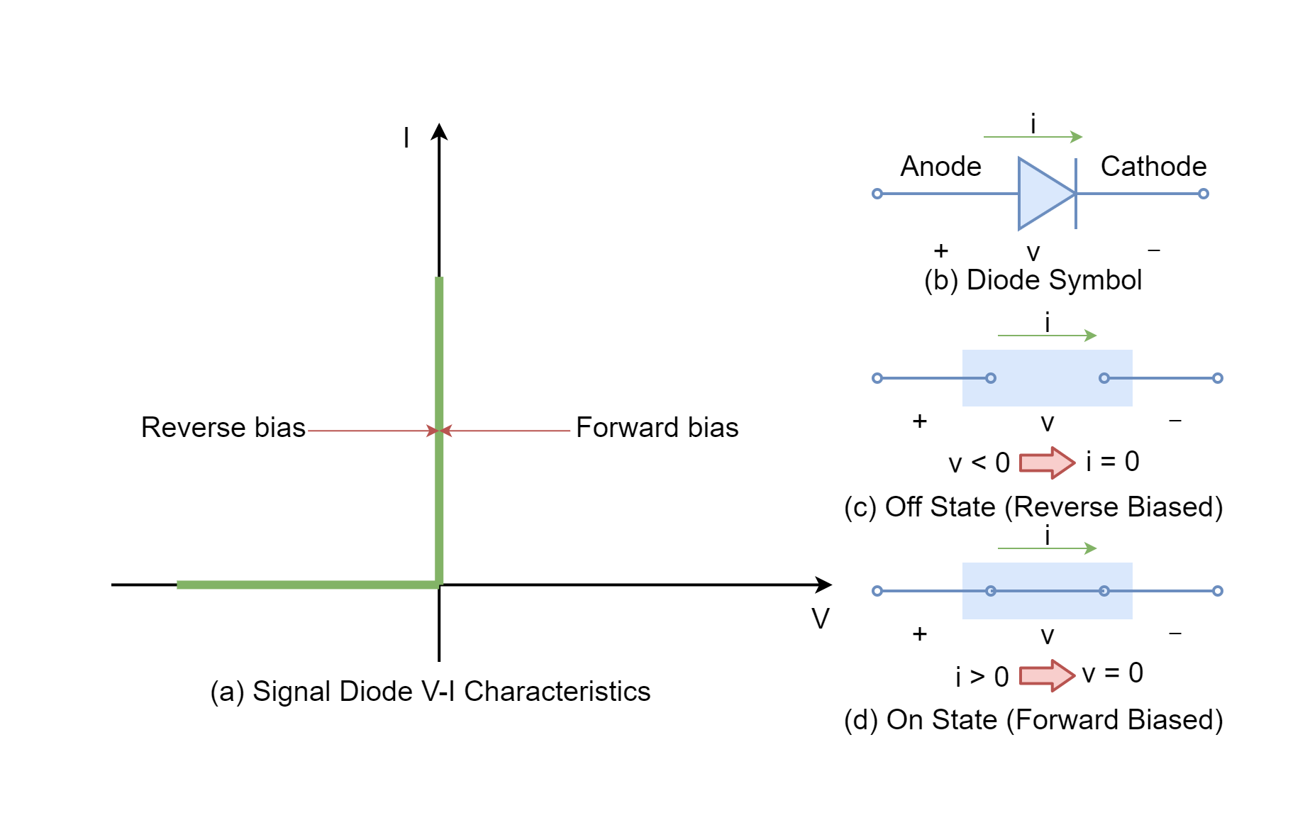
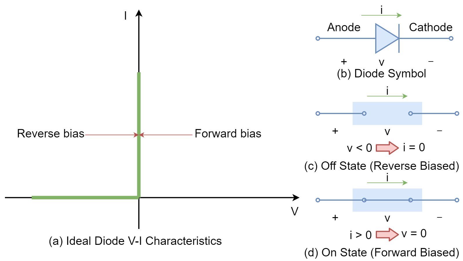
Ideal Diode
The ideal diode is the one that does not have any drift current due to minority carriers and no barrier to overcome. It is simply, an ON & OFF device depending on the polarity of the supply voltage. The symbol of the diode and its V-I characteristics (ideal) along with states of the diodes are shown in the following figure (1).
When a voltage source is connected to a diode in the way that anode is connected to (+) and the cathode is connected to (-) terminal of supply then the diode is said to be operating in a forward direction (forward-biased). The reversal of supply terminals, makes the diode operate in the reverse direction. In a forward-biased ideal diode, the diode/ switch becomes closed and maximum current starts to flow with the fraction of voltage applied. In the reverse direction, the ideal diode operates in an open state, and no current flows irrespective of the applied voltage. The ideal diode describes the states of switch i.e. ON & OFF under forward and reverse bias.
Real Diode
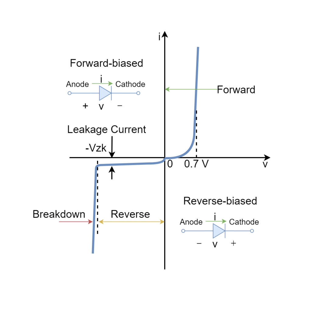
In a real diode, the V-I characteristics are more complex compared to the ideal diode and depend on many factors such as doping level, operating temperature, physical size, and semiconductors used in fabrication. The V-I characteristics of a real diode can be divided into three regions: forward, reverse, and breakdown. The V-I characteristics of a typical diode are depicted hereunder:
Figure 2: The typical characteristics of a signal diode along with biasing conditions
Forward-biased Region
Under the forward biasing condition, the diode does not conduct until a certain level of voltage is applied. The level of voltage that permits the flow of current depends on the barrier voltage of that specific PN junction. Once the level of voltage applied crosses the barrier voltage, the PN junction of the diode allows the current to flow through it. The relationship between V & I is exponential (non-linear) and is depicted in the above figure. In the forward region, the current increases rapidly with the little increase in voltage, and as such a current limiting resistance is recommended to be used in the diode to avoid going beyond the maximum power dissipation of the diode.
Reverse-biased Region
When the diode is reverse biased, a negligible amount of current flows which is specifically as drift current. This current is dependent on the temperature and is due to minority carriers. The drift current is of very low magnitude and neglected to allow supposition that no current flows through the reverse-biased diode. The diode is said to be in an off state until the breakdown region is reached. It is good practice to add a series resistor to the reverse-biased diode as the diode under this state is open and all of the voltage will appear across the diode under the absence of the series resistor. The resistor, in series with the reverse-biased diode, shares the voltage drop and protects the diode.
Breakdown Region
The diode resists the flow of current in reverse biasing until a certain level of voltage is achieved i.e. breakdown voltage. The current flow is similar to forward-biased current but in opposite direction and under different phenomena. In this region, the diode does not get damaged as long as the power dissipation rating of the diode has not been compromised. Therefore, it is always a good practice to add a series resistor to the diode.
Types and Usages
The signal diodes are typically used for signaling, switching, and for processing of information. The signal diodes can pass high-frequency signals and allow currents up to 150 mA leading to a smaller size. They are mostly used in digital logics, wave clipping, television and radio circuits, etc.
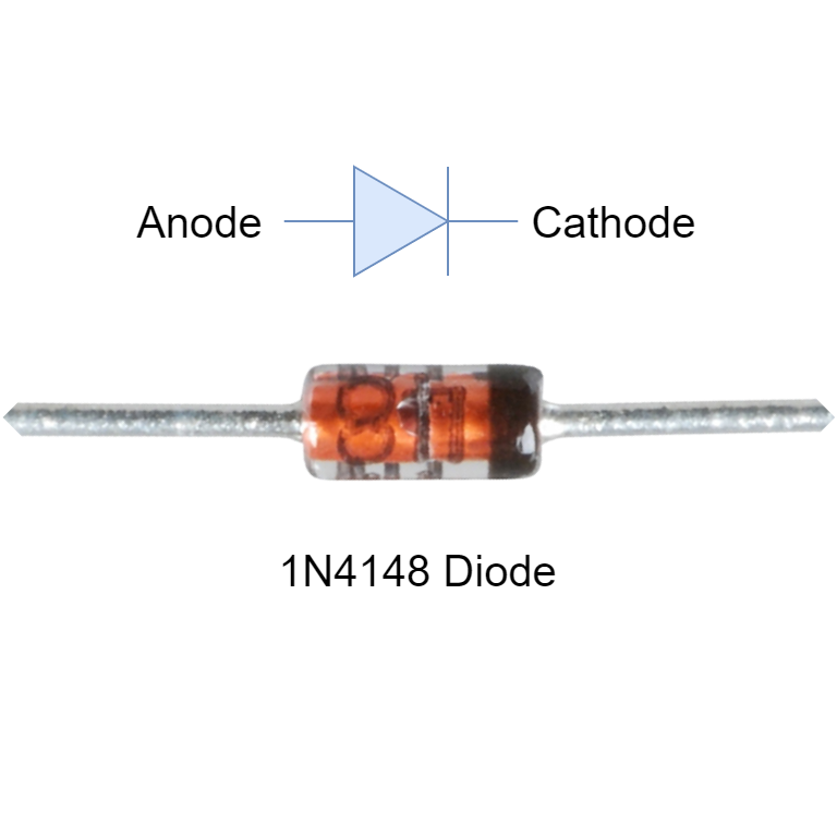
The diodes usually carry a marking to identify the cathode terminal in order to place them correctly in the circuit. Commercially available diode (1N4148) along with its cathode marking is shown in figure (3).
Figure 3: Commercially available signal diode (1N4148) along with symbol and marking.
The semiconductor material used in the fabrication of diode contributes certain properties:
Silicon Signal Diodes
Low forward resistance
High reverse resistance
Junction voltage drop around 0.6 to 0.7 V
High forward current and reverse voltage
Germanium Signal Diodes
High forward resistance
Low reverse resistance
Junction voltage drop around 0.2 to 0.3 V
Low forward current and reverse voltage
Signal Diode Specifications
There are many variants of signal diodes that are commercially available and the manufacturing process of signal diodes induces different specifications & properties to sustain under varying conditions & applications. The manufacturers supply datasheets of signal diodes to allow engineers to select them according to their requirements/ applications. The most important ratings/ specifications of signal diodes are as follow:
Total Power Dissipation (PDMAX)
It indicates the maximum power that can be dissipated when the diode is forward biased. The diode offers some resistance due to the PN junction and drops certain voltage across the diode. The multiplication of voltage drop across the diode and current passing through the diode gives power dissipation. Power dissipation above the maximum rated value can damage the signal diode and as such should be avoided by restraining the power dissipation within the limits.
Maximum Forward Current (IFMAX)
It is the maximum allowable forward current through the signal diode. The PN junction of the signal diode offers resistance and the current passing through resistance produces heat. The heat increases with the increase in current and may cause thermal overload/ failure of the signal diode. The signal diode has limitations in forwarding flow of current and to remain under the limit a series resistor is used. For power diodes, the heat sinks are used to reduce the temperature as well.
Peak Inverse Voltage (PIV)
It is the maximum peak reverse voltage that can be applied to a signal diode. It is to ascertain that the signal diode does not enter into the breakdown region when operated at this voltage. This rating is considered when the diode is operated in reverse conditions i.e. freewheel diodes or rectifier diodes.
Maximum Operating Temperature
This is relevant to the thermal stability of the diode and the PN junction of the diode heats up due to the flow of current. The rising temperature can deteriorate the anatomy of the diode and should be avoided by considering maximum operating temperature besides power dissipation & forward current. The ratings of the signal diode are usually given at different ambient temperatures as they play a vital role in the stability of the diode.
Practical Applications
There are many applications of the signal diode in low power and high-frequency circuits involving wave-shaping, clipping, protection, and switching, etc. A few of them are explained below:
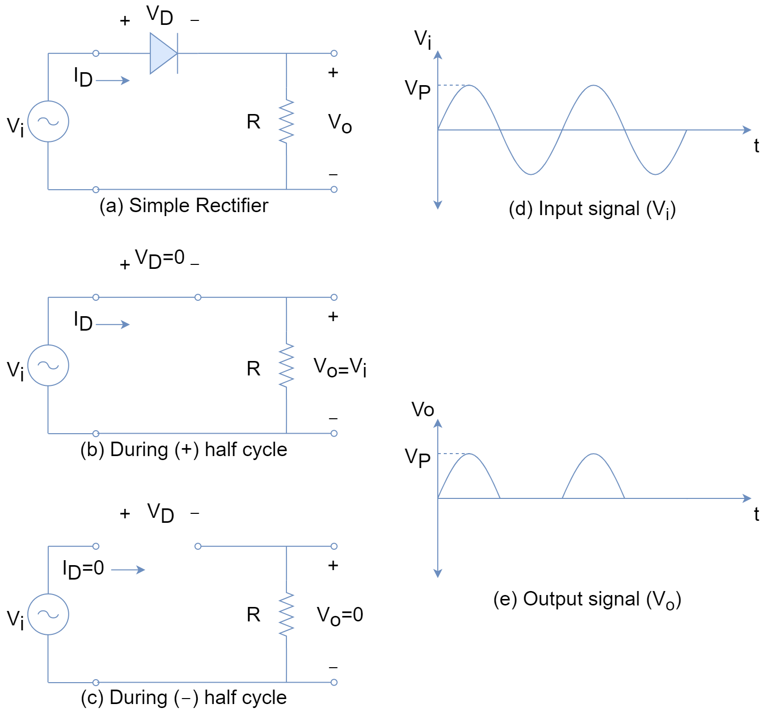
The Rectifier
When an alternating signal (sinusoidal) is applied to a signal diode then it alternates its state in-between forward (on) and reverse (off) regions. This effectively makes the signal diode conduct in the first half-cycle and not conduct in the second half-cycle. The states of diodes in forward and reverse biasing are shown in figure (4). The signal diode as a rectifier is used only in low power circuits and for high power circuits, a rectifier or power diode is used.
Figure 4: The simple rectifier circuit
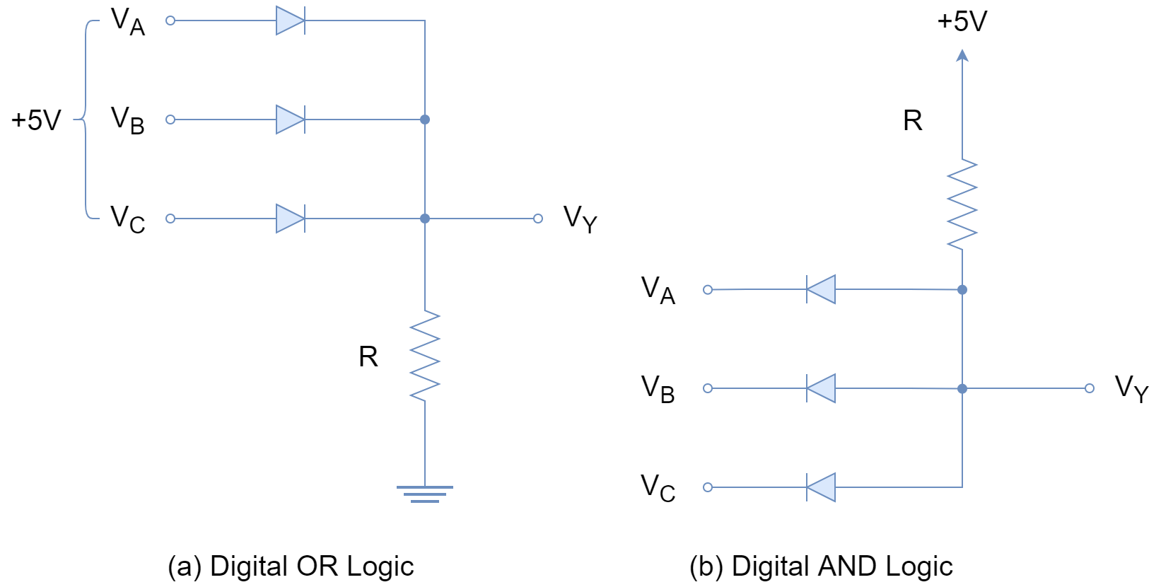
Digital Logic Gates
Another application of signal diode is in digital circuits for the implementation of logic. The following figure is framed on the basis that zero (0) voltage corresponds to logic zero (0) and +5 V to logic one (1). In part (a) of the figure (5), OR logic is implemented and any of three inputs [VA, VB or VC] gives VY = +5 V (logic 1). For logic zero (0) all of the inputs need to be at 0 V to turn off all the diodes.
Y = A + B + C
In part (b) of figure (5), AND logic is implemented, and to give logic one (+5 V) all of the inputs/ diodes [VA, VB & VC] need to be turned off. When any of the diodes is conducting (on) then it effectively makes the output VY = 0.
Y = A · B · C
Figure 5: Implementation of OR & AND logics using signal diodes.
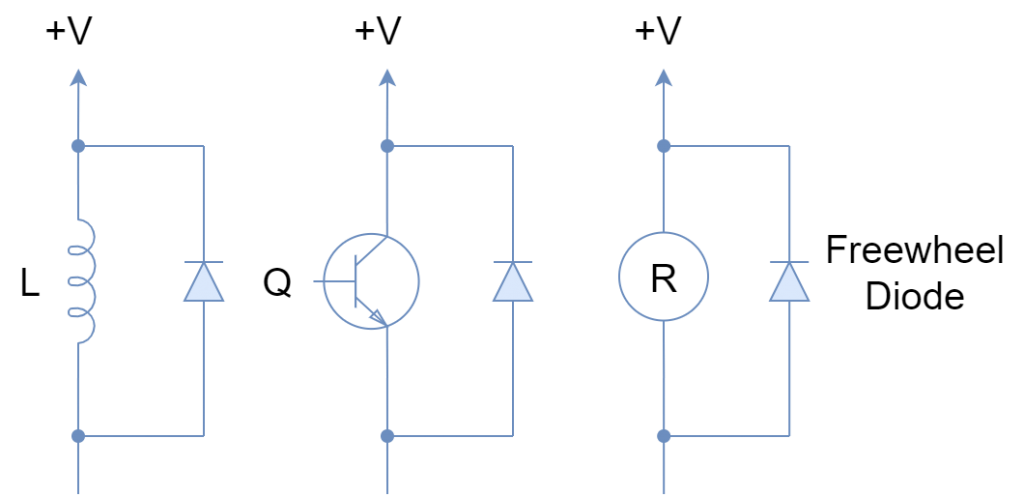
Freewheel Diodes
The signal diodes can be used to protect delicate components from voltage spikes or transients. These voltage spikes or transients are produced due to the fast switching of devices or changing the state of energy storing elements. The signal diode is placed in a reverse biasing state in parallel to the device that requires protection. Such position of a diode in circuit names it “Free Wheeling Diode” or “Fly Wheel Diode”. In the following figure (6), a few freewheel applications of the diode are shown. During on state of the device, the freewheel diode is reverse biased and all of the current flows through the device. As soon as the device turns off, the reverse voltage produced in the inductor makes the freewheel diode forward biased and all of the energy is suppressed through the diode. Similarly, in semiconductors, the freewheel diode protects sensitive components from sudden and accidental reverse voltages.
Figure 6: Examples of Freewheel diodes
Conclusion
The signal diode acts as a switching device alternating between ON & OFF states.
In a forward-biased diode, the current flow is due to majority carriers i.e. diffusion current.
In a reverse-biased diode before the breakdown, the negligible amount of current flows called drift current or saturation current and is majorly dependent on the temperature.
In reverse-biased diode on achieving breakdown, the significant amount of reverse current flows and that may damage the diode under the absence of protections.
The signal diodes are typically used in low-power and high-frequency circuits.
The applications include rectification, digital logic and freewheeling, etc.
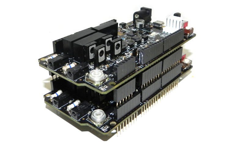
NeuroStimDuino was designed to help anyone with an interest in neuroscience—students, researchers, and hobbyists alike—to study the effects of neurostimulation on muscle contraction. It comes with an I²C interface through which external microcontroller boards like the Arduino Due can be used to generate different stimulation patterns and control other aspects of its operation. Each NeuroStimDuino shield has two independent output channels, which can be used to alternate the contraction of flexor and extensor muscles or to contract various muscles simultaneously. By stacking multiple shields, additional output channels can be made available.
Features
Generates biphasic, rectangular, and constant current stimulation pulses with programmable frequency, pulse-width, and amplitude
Stimulation pulses are charge-balanced, consisting of a cathodic phase followed by an anodic phase of equal or unequal amplitudes (i.e. the waveform shape can be symmetrical or asymmetrical).
Can be configured, over I²C, from an external microcontroller acting as the controller
Can be used as an Arduino shield due to pin-compatibility with Arduino Due and MEGA boards
Has two independent output channels per board. Multiple boards can be stacked to generate up to 256 channels.
Onboard opto-isolators separate digital and analog signals
Can be powered by a 9 V battery connected to a DC input or by an external 5 V input on VIN. For proper operation, we recommend two Li-Ion batteries (e.g. 18650s) connected in series. (Batteries not included.)
Onboard LEDs visually indicate when neurostimulation is delivered, and a precision current-sense amplifier provides a voltage output proportional to the stimulation current.
Includes several safety features such as fuses, an emergency OFF switch, and solid-state relays to shunt inputs with low impedance resistors
Comes with a pair of 2 mm pin-style lead wires to connect with standard, reusable, hydrogel-based stimulation electrodes
The optional Accessory Kit includes four 1.25-inch round and four 2-inch square hydrogel electrodes, a pair of lead wires, and a pair of bifurcation cables.
Technical Specifications
Adjustable current output range: +/- 25 mA, resolution 250 µA/step
Adjustable stimulation frequency range: 1 – 100 Hz, pulse-width 0 – 2 ms
Maximum compliance voltage: +/- 72 V
The onboard 16-bit dsPIC33F Microcontroller (40 MIPS, 256 KB flash memory) operates as an I²C peripheral with a programmable, 7-bit address.
Stimulation current output can be measured using the onboard 12-bit ADC or an external ADC.
The PCB includes a microUSB interface but the components are not populated. (Upon request, we are happy to provide a list of the necessary components.) If populated, this interface can be used to control NeuroStimDuino from a PC by way of serial commands.
The project is live on crowdsupply and ends in 37 days,
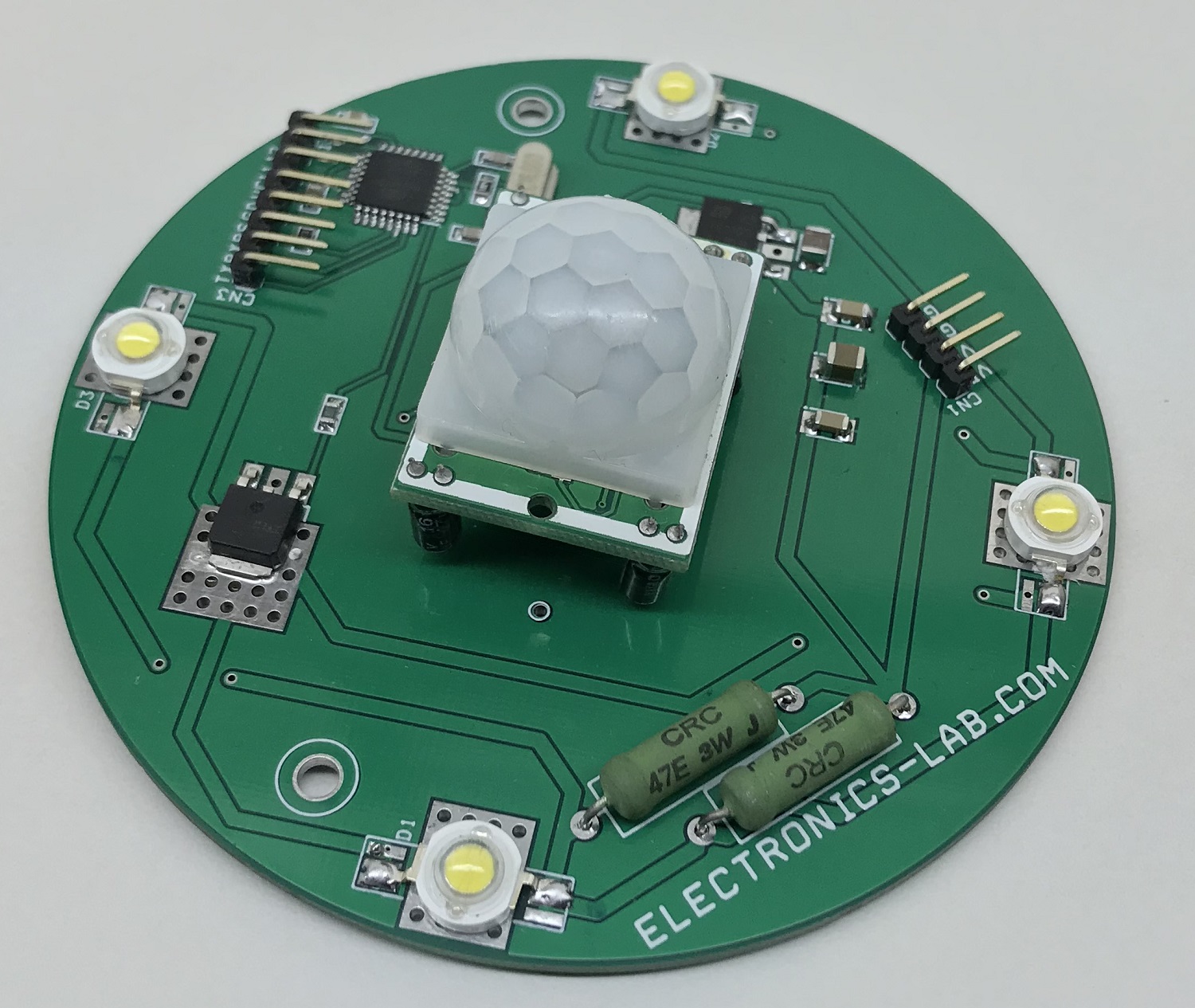
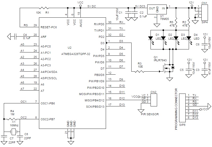
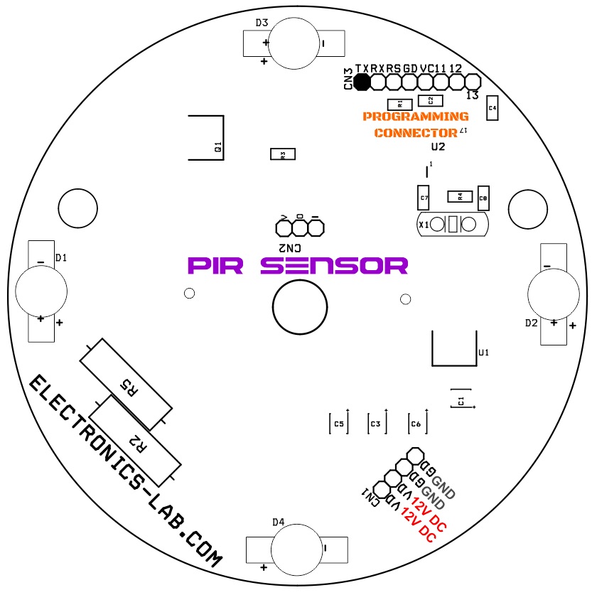
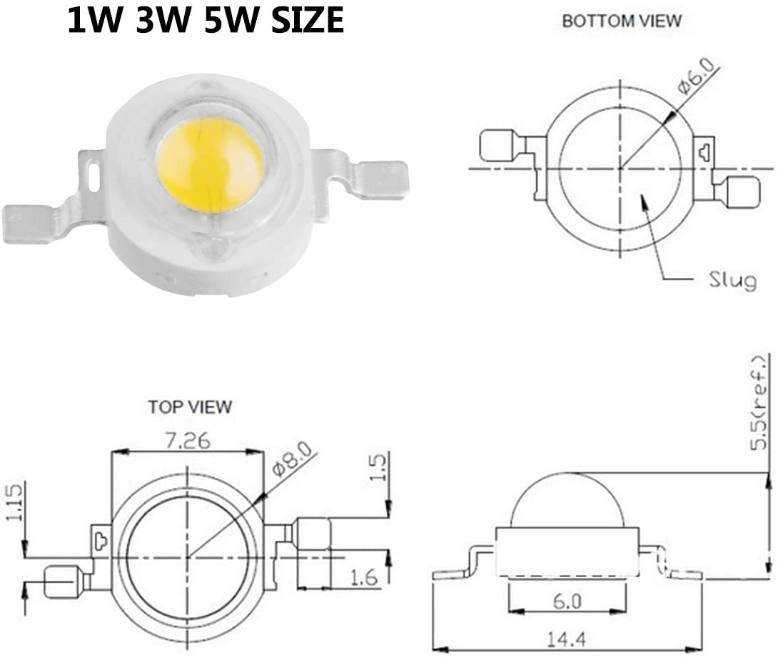
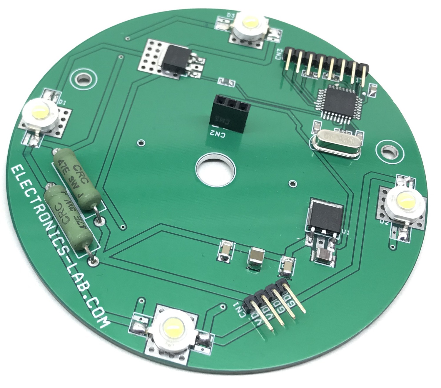
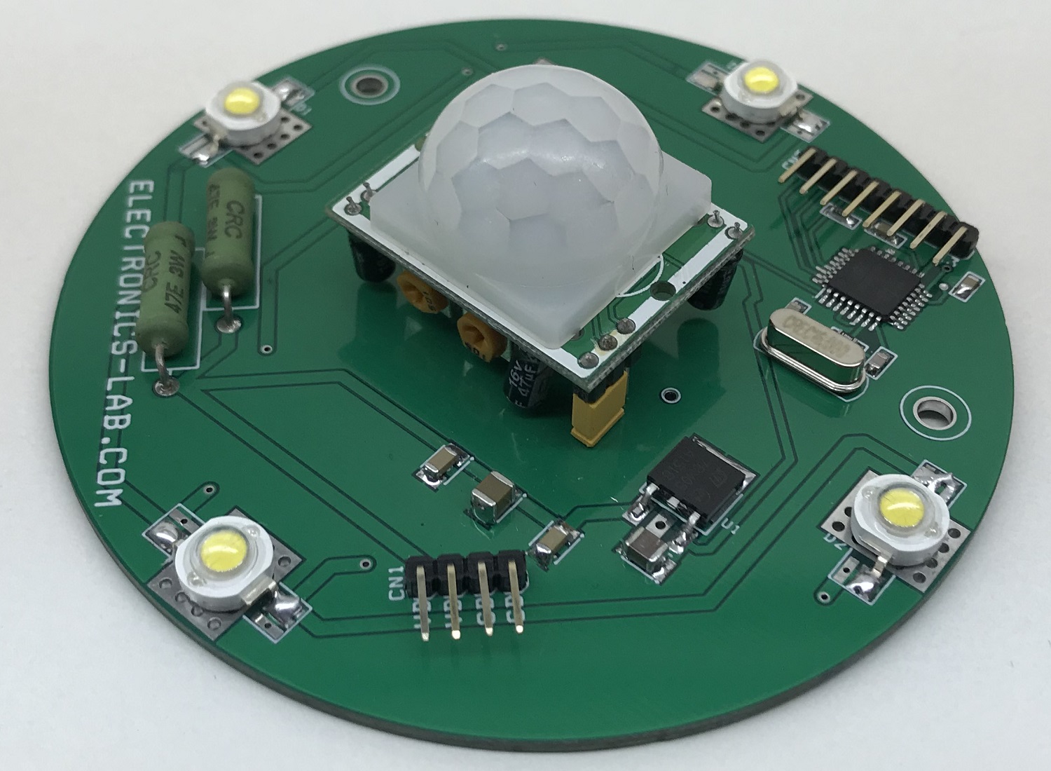
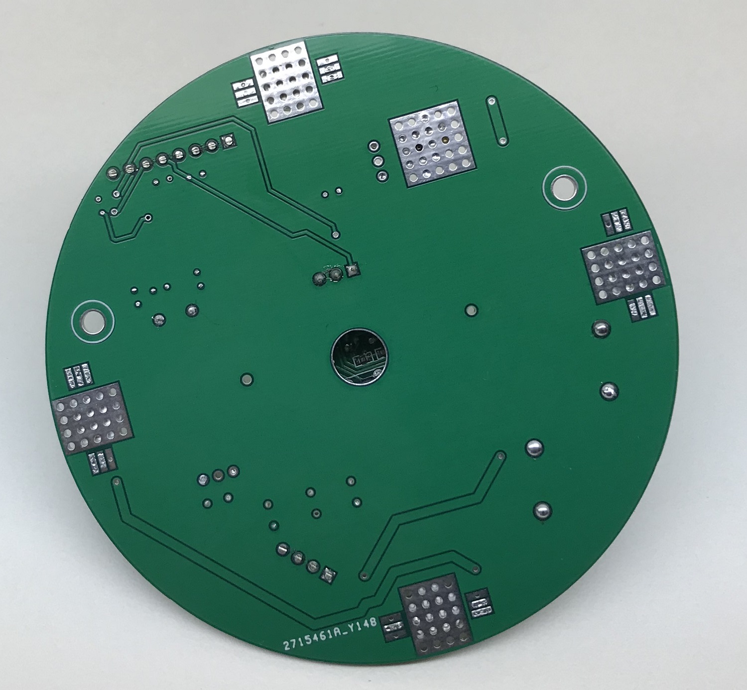
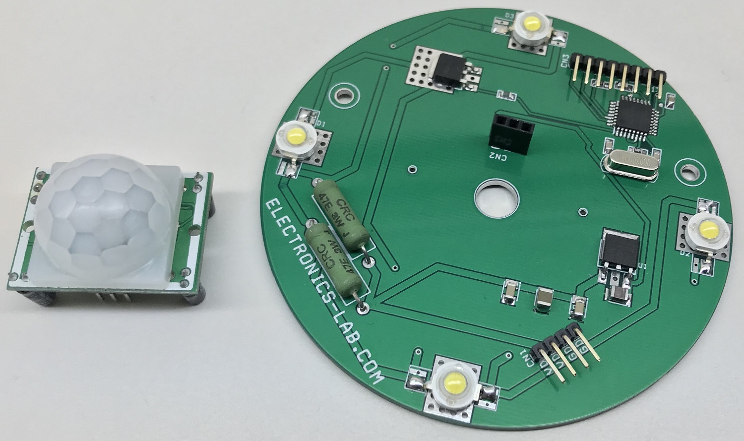
This motion sensor LED ceiling light board has been designed using 4 white LEDs each of 1-3W, PIR sensor module, Atmega328 microcontroller, low ohm IRLR7843 MOSFET, and few other components. The PIR sensor detects the infra-red rays emitted by human motion within the detection area and switches on the 4 white LEDs for 10 seconds. The project helps in energy-saving applications and new green building projects. Detecting distance: 1 to 20 feet. Detecting angle: 360 degrees. Installation height 2-15 feet. 2 mounting holes are provided to mount this board. It is advisable to use this board indoors.
The operation of this circuit is simple, the motion sensor provides a TTL output pulse when it detects the human presence, then the ATmega328 microcontroller detects the trigger on digital in D12 and sets the digital pin D3 high for 10 seconds, this high signal triggers the MOSFET which drives power to 4 LEDs in parallel. Resistors R2 and R5 act as current limiting resistors, U1 is a 5V regulator that provides 5V DC to the microcontroller and sensor from an input supply 12V DC. The operating power supply is 9-12V DC and its draws 500mA of current. The project tested with 3W white LEDs, but any other LED can be used, but take care of current limiting resistor R2 and R5 respectively to LEDs current requirements. CN1 4 pin male header is provided for power input, CN2 SIP8 connector provided for bootloader burning and programming using Arduino IDE.
Programming the Atmega328
The project is Arduino compatible and can be used in many lighting applications. You will have to just write your own code and program it to Atmega328. Example Arduino code is provided to help you to test the project. The code will turn the LEDs ON for 10 seconds when it detects human motion and may repeat if still motion is detected again. The user may easily increase the LED on time in Arduino Code. Arduino digital pin D12 connected to the PIR sensor module and D3 drives the LEDs.
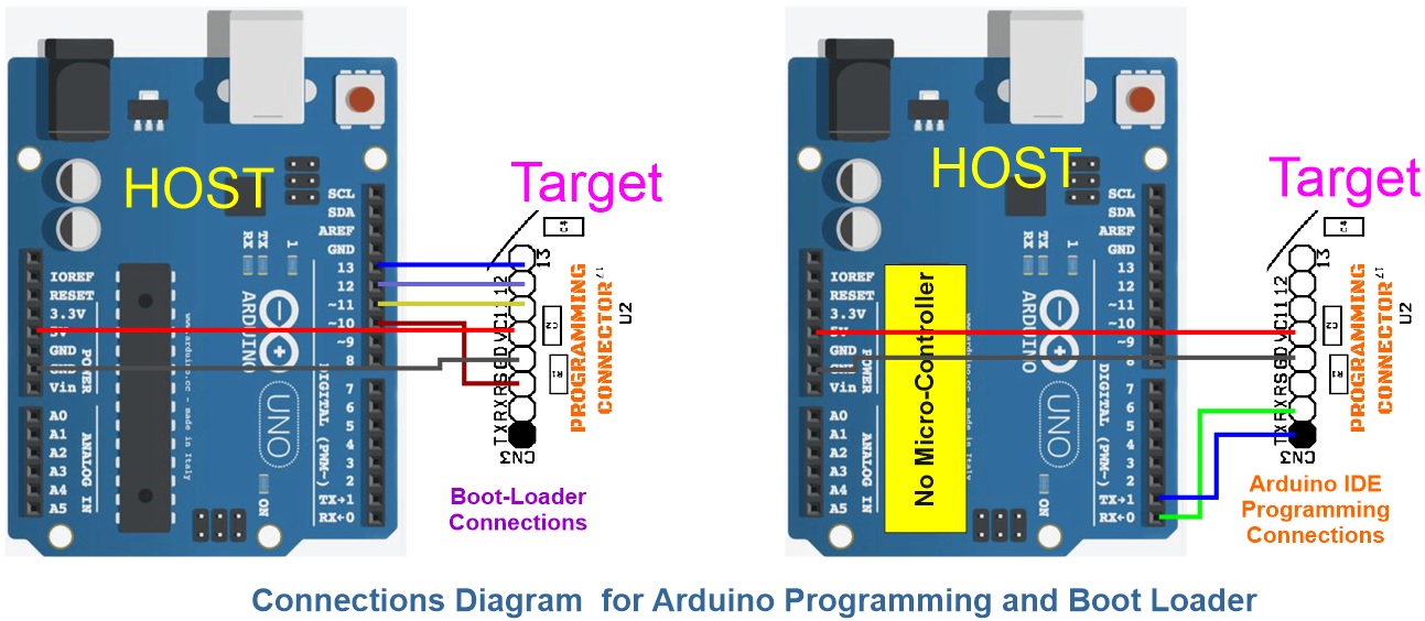
Note:A new Atmega328 Microcontroller requires Bootloader and Code uploading, SIP8/CN2 connector provided for both, more information is available here
Please refer to the programming connection diagram above to program the board. Arduino example code is available at the download link at the end of the page.
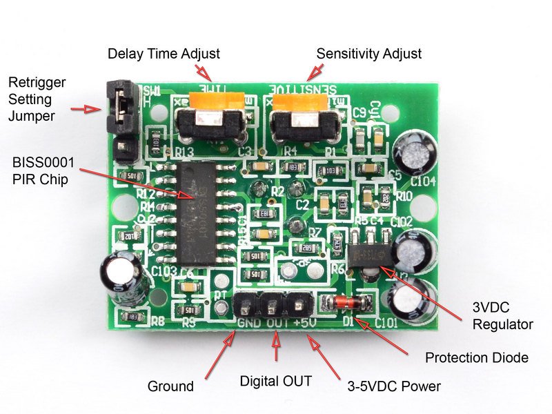
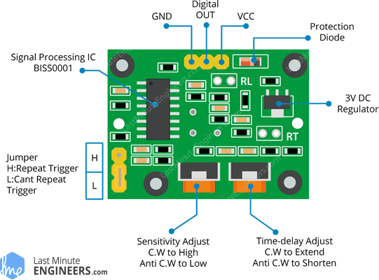
PIR Motion Sensor
PIR sensors are used to detect motion from pets’ humanoids from about 20 feet away. The operating principle of such sensors is straightforward: a crystalline sensing element generates an electric charge when exposed to infrared radiation, such as body heat. The more infrared radiation present, the higher the voltage generated. A Fresnel lens is used to focus the infrared radiation on the sensor, and an onboard amplifier boosts the signal and trips an output if it starts changing too rapidly.
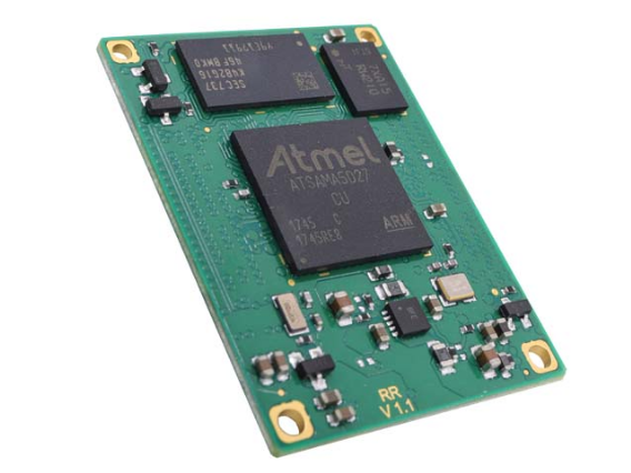
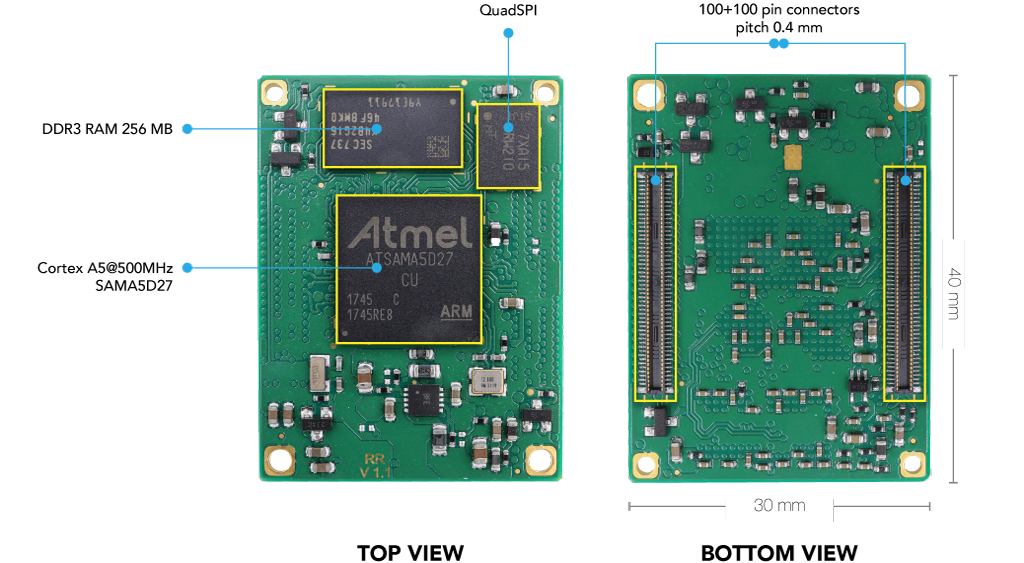
Acme Systems recently launched a series of systems-on-modules (SOMs) based on the Microchip SAMA5D27 microprocessor, which is ideal for extreme-low-power projects that still require a full Linux kernel and operating system, dubbed the RoadRunner. At the core of the RoadRunner is a Microchip MPU, which is designed for low power consumption, and it features an optimized PMIC [Power Management Integrated Circuit], a low-power RAM, and the Quad-SPI [flash] memory. The module is designed for even heavy industrial use, that is why the ten-layer board operates between -40 and 85°C (around -40 to 185°F) and boasts of a 10mW “freeze mode” sleep with full wake-up clocking around a second.
The SAMA5D27 microprocessor is a high-performance, low-power Arm cortex-A5 CPU embedded microprocessor running up to 500MHZ with the integration of multiple memories such as DDR2, DDR3L, LPDDR2, LPDDPR3, e.MMC Flash and QSPI. This microchip offers advanced security functions like Arm Trust Zone, tamper detection, secure boot, and secure data storage with full integration of robust peripherals for connectivity and user interface applications as well as high-performance crypto accelerators AES, TRNG, and SHA. The SAMA5D2 series is packaged with free Linux distributions, MPLAB X IDE, MPLAB Harmony v3, and bare-metal C examples. The SAMA5D27 has an added industrial temperature range operation (-40°C to 105°C external temperature).
The SAMA5D27 features 128kB L2 cache which can be configured as an internal 32-bit single-cycle static RAM (SRAM), 5kB of internal scrambled SRAM of which 4kB are automatically erasable on tamper detection, and 256 bits of scrambled and erasable registers. It also enables 256MB of DDR3L memory, up to 128MB of QSPI flash, an Arm NEON coprocessor, hardware floating-point unit, and hardware cryptographic acceleration including a FIPS-compliant true random number generator. The module is connected to a carrier board via two Hirose 100-pin connectors which relays signals including 10/100 Ethernet, an 24-bit RGB LCD interface, resistive and capacitive touch interfaces, SSC/I2S, I2C, SPI, QSPI.
It also features a stereo audio amplifier, peripheral touch controller, PDMIC, CAN-FD MCAN, up to 128 GPIO lines, and up to 12 12-bit analogue-to-digital converters (ADCs). it enables five USART, five UART serial ports and an additional receive-only UART, and two USB High Speed hosts or one host and one device. Additional features include; USB High-Speed Inter-Chip HSIC interface, SDIO, SD, or MMC hosts, image sensor controller, timers, PWM, up to three programmable clocks, a JTAG port, serial debug port, and a battery input for the internal real-time clock.
Specifications of the Microchip SAMA5D27 Microprocessor includes:
Low System Cost and High Value Integration:
Peripheral Touch Controller
o Embedded audio subsystem
o 0.8mm ball pitch package reduces PCB design complexity
o Simple power management scheme
Ultra-Low Power Consumption:
o Low-power architecture for extensive battery life
o <200uA retention mode with fast wake-up
o 5uA in backup mode
• State-of-the-Art Security:
Secure Boot
o Execution of encrypted code with an “on-the-fly” encryption-decryption process
o Integrity Check Monitor of the memory content
o Hardware encryption engine
o Tamper pins and secure key storage
Extensive Ecosystem:
Free Linux® distributions
o MPLAB X Integrated Development Environment
o MPLAB Harmony
o Complete set of C examples for bare metal users
o Multiple third-party software and hardware partners
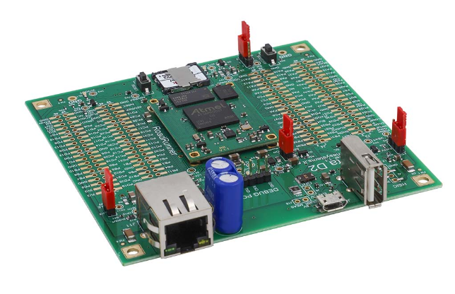
“The Berta-D2 is the basic evaluation board for the RoadRunner system-on-module,” the company states, for those who do not want to build their own carrier in the initial prototype phase of a project. It includes the bare essentials for turning on the RoadRunner, running Linux, and experimenting with network and USB host and system capabilities. It also includes 160 pin 2.54 mm pitch pads that include all of the signals exposed by the RoadRunner module, allowing you to experiment with your own interface.”
Acme Systems is now selling the modules for €36 (approximately $43), with the Berta-D2 carrier costing an extra €30 (approximately $36). You can find more information on the product’s home page.
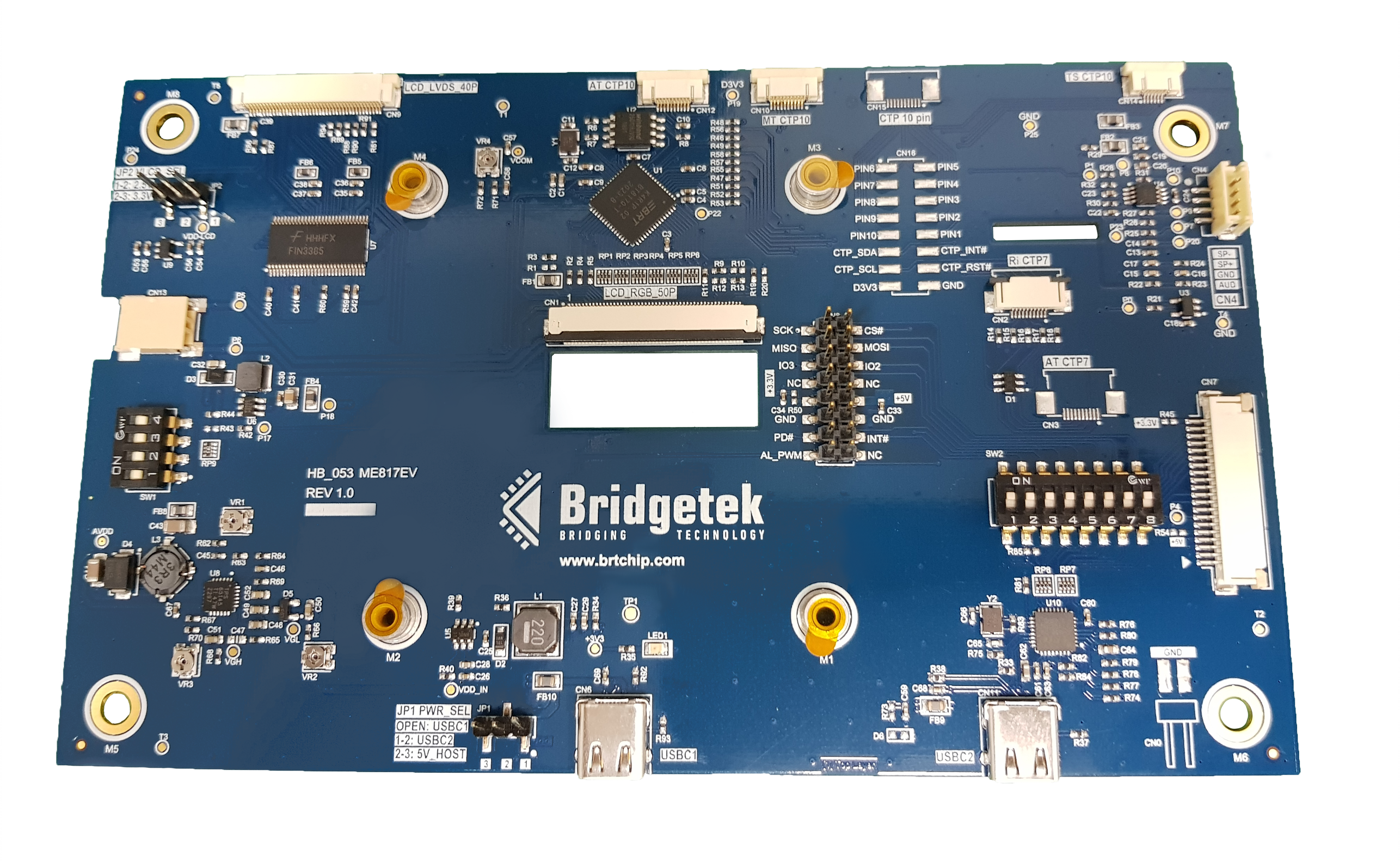
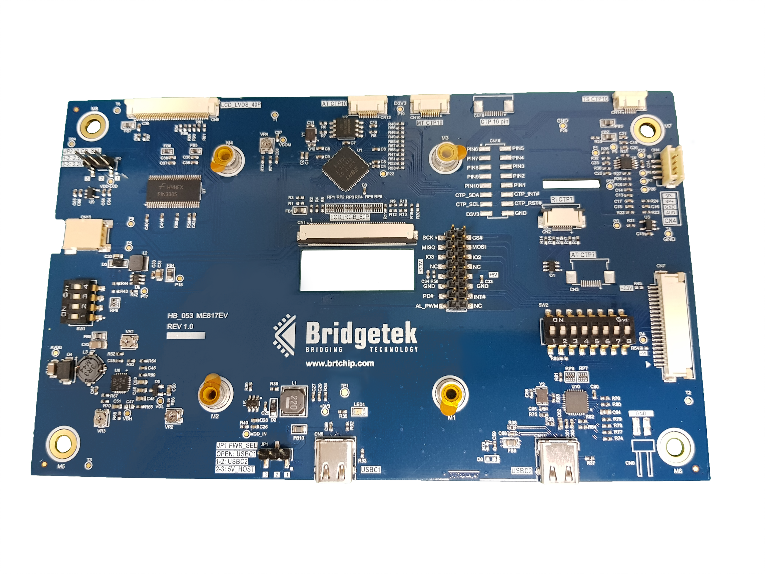
To assist with the initial development and prototyping of human-machine interfaces (HMIs) based on its object-oriented graphic controller ICs, Bridgetek has announced the availability of the ME817EV evaluation board. Featuring the company’s BT817 embedded video engine (EVE) device, it allows engineers to experiment with the latest generation of EVE technology and get a comprehensive understanding of the breadth of its capabilities. Thanks to the higher resolutions and large format display that the BT817 supports, more compelling and functionality-rich HMIs can be created, with greater visual clarity and enhanced video playback capabilities.
Measuring 165mm x 100mm, the ME817EV unit has all the necessary attributes for undertaking development work relating to the graphics, audio, and touch elements of the HMI. As well as audio amplification and multi-stage audio filtering features, there is an LED driver which can be used to adjust the display backlighting. Also included is a touch controller that supports 5 simultaneous touch points, plus 16Mbytes of on-board flash memory resource for storing Unicode fonts, image libraries, etc.
The ME817EV can interface with large-scale, high-resolution display modules. For 1280×800 pixel displays, it can connect through a 40-pin LVDS interface, while for 1024×600 pixel displays a 50-pin RGB interface can be used. Capacitive touchscreens may be connected using a 10-pin or 6-pin FPC connector. The board can be powered via a 5V supply using the SPI host connector, or via the USB Type-C port.
As Bridgetek founder and CEO Fred Dart explains;
“We have already seen a great deal of commercial traction for our fourth generation EVE chips, across a broad spectrum of industry sectors. It is clear that there is a real need for a more streamlined approach to larger format HMI construction. By providing this evaluation platform, we are making the whole project development process a lot quicker and easier for engineers to complete, with much better end results being derived too.”