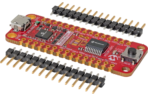
Microchip’s low-cost evaluation kit for the PIC18F16Q41 8-bit microcontroller (MCU)
The PIC18F16Q41 Curiosity Nano evaluation kit from Microchip Technology is a hardware platform to evaluate MCUs in the PIC18FQ41 family. This board has the PIC18F16Q41 MCU mounted. Supported by MPLAB® X IDE, the board provides easy access to the features of the PIC18F16Q41 to explore how to integrate the device into a custom design. The Curiosity Nano series of evaluation boards include an on-board debugger. No external tools are necessary to program and debug the PIC18F16Q41.
With the award-winning MPLAB X integrated development platform and MPLAB Code Configurator (MCC), the kit provides access to the intelligent analog and core independent peripherals on the PIC18F16Q41. MCC is a free graphical programming tool for configuring a rich set of peripherals and functions specific for user applications. Users can take their next idea to market with a development board that they can keep in their pocket. With full programming and debugging capabilities, the PIC18F16Q41 Curiosity Nano evaluation kit has pre-programmed firmware to start development immediately.
Features:
PIC18F16Q41 MCU
One mechanical user switch
On-board debugger
Board identification in Microchip MPLAB X
One green power and status LED
Programming and debugging
Virtual serial port (CDC)
One logic analyzer channel (GPIO)
One yellow user LED
USB powered
Adjustable target voltage
MIC5353 LDO regulator controlled by the on-board debugger
1.8 V to 5.5 V output voltage (limited by USB input voltage)
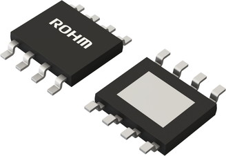
ROHM’s BD9G500EFJ-LA is a 7 V to 76 V input, 5 A integrated high-side MOSFET, single buck DC/DC converter
ROHM’s BD9G500EFJ-LA is a buck DC/DC converter with built-in low on-resistance high-side power MOSFET. It is capable of providing a current of up to 5 A. Current mode architecture provides fast transient response and simple phase compensation setup. The operating frequency is adjustable from 100 kHz to 650 kHz.
Features:
Long time support product for industrial applications
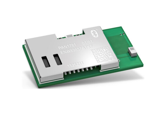
Lightweight evolution – and a new member for the Nordic Semiconductor-based Bluetooth Module family: The new PAN1781 from Panasonic Industry suits a wide range of mid and high-volume application designs.
“With the PAN1781 being the little brother of our undoubtedly successful PAN1780, we are now rounding out our module range on the lower ends”, opens Jan Scheller from Panasonic Industry.
The PAN1781 is a Bluetooth® 5 Low Energy module based on the Nordic nRF52820 single-chip controller and is, in a way, the lightweight version of the PAN1780. Bluetooth® 5 features additionally a higher symbol rate of 2 Mbps using the high-speed LE 2M PHY or a significantly longer range using the LE coded PHY at 500 kb/s or 125 kb/s. The new channel selection algorithm (CSA#2) improves the performance in high interference environments. Furthermore, the new Low Energy advertising extensions allow for much larger amounts of data to be broadcasted in connectionless scenarios.
“The module is an attractive solution because of its truly flexible usability enabled by the attractive software stacks available via the Nordic portal, for instance Bluetooth® Low Energy 5.1, ZigBee and Thread”, continues Scheller. “Thus, the PAN1781 is an allrounder that perfectly qualifies for many different applications and markets. It comes with the same specs as the PAN1780, but due to its reduced memory it is a highly economical choice for each context that requires an essential Bluetooth® interface.”
An output power of up to 8 dBm and the high sensitivity of the nRF52820 in combination with the LE coded PHY render the module an ideal choice for applications, where a long-range is required.
Additionally, the module’s ultra-low current consumption is highly beneficial for modern battery-powered devices.
With the Cortex® M4 processor, 32 kB RAM, and the built-in 256 kB flash memory, the PAN1781 can easily be used in standalone mode, thereby eliminating the need for an external processor, saving complexity, space, and cost. The PAN1781 also supports angle of arrival (AoA) and angle of departure (AoD) direction finding using Bluetooth®.
Scheller concludes:
“With the new PAN1781, we clearly address mid and high volume designs from customers valuing high quality, long availability and Panasonic Industry’s high level support throughout the whole design-in period – and even beyond”.
Compact electronic devices rely on concise li-ion battery packs. Lithium iron phosphate battery (LiFEPO4) or LFP battery is a type of lithium-ion battery that uses lithium iron phosphate as a cathode and a graphitic carbon electrode as the anode. LFP batteries have a lower operating voltage and also present lower electrical conductivity. But they have some significant advantages over lithium-ion batteries like low toxicity, low cost, high stability, high performance, etc. Due to these advantages, LFP batteries find several roles in automotive industries, Uninterruptible power supplies, and other low power applications.
LFP batteries have a very constant output voltage that stays fixed around 3.2V (nominal voltage of the battery) during discharge cycles. They also have a longer calendar life. Calendar life or shelf life is the time for which a battery can store charge being inactive or with minimal use. Other than that, LFP batteries are thermally and electrically stable, which makes them safer than traditional LiCoO2 batteries.
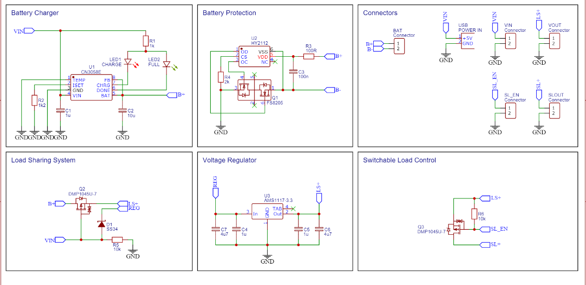
LFP Power Board
Stefan Wagner from Germany designed a PCB for LFP batteries power board. The board can charge LiFePO4 batteries and also power the load uninterruptedly. The board is developed for 3.3V projects and can be operated by both battery and external power supply.
The board uses CN3058E battery charger IC and HY2112, a battery-pack protection IC. There is a load-sharing system that interrupts the connection between the battery and the load when an external power supply is connected. The load-sharing system is implemented by a pass transistor and a Schottky diode. When an external voltage is detected at the gate of the pass transistor, the voltage from the battery is interrupted.
Without an external power supply, the project is powered directly by the battery, which means that the output voltage depends on the battery charge level (about 2.7 – 3.5V). However, an onboard 3.3V regulator is present that can supply a constant 3.3V to the load.
The battery charger section consists of CN3058E IC, a couple of resistors to set charging current, a couple of LEDs for indication, and bypass capacitors. The CN3058E is a complete constant-current/constant-voltage linear charger for single-cell LiFePO4 rechargeable batteries. The IC contains an on-chip power MOSFET and thus, eliminates the need for the external sense resistor and blocking diode. The device has an automatic low-power sleep mode which activates when the external supply is not present. It can also automatically recharge the cells by sensing the battery voltage regularly. The charge current can be programmed externally with a single resistor, and the maximum programmable current is 1A.
The battery protection unit is based on HY2112 IC that is designed for LiFePO4 rechargeable battery protection. The device consists of high-accuracy voltage detectors which monitor the cell voltage and determine whether the cell is operating in its safe operating area. It also contains internal delay circuits, which eliminate the need for external capacitors. The IC is used along with two FETs to control the charging and discharging of the batteries. R3 is a current limiting resistance and is kept as small as possible so that overcharge detection accuracy is not affected. R4 is also for current limiting and it must be around 2k or higher. R4 will prevent current when a charger is in reversed polarity.
Furthermore, the board is equipped with an additional output port (SL) that can be switched via the built-in MOSFET. If the EN pin is pulled to the ground, for example via a GPIO pin of a microcontroller, then the SL output is activated.
To summarize, this board is a complete solution for LiFePO4 batteries. It allows charging, discharge control, consists of an onboard battery protection system, and also has an additional output port.
DC-DC converters are needed in almost every commercial product, whether it is industrial, medical, defensive, automotive, or any other application. These converters are electronic circuits that can convert the DC voltage from one level to another. There are two types of DC-DC converters: linear and switching converters. Linear converters are resistive which means that they use resistive voltage drop to create a regulated output voltage. This also means that the input voltage should always be higher than the input voltage, and linear converters can only step down a voltage level. On the other hand, switching converters perform the conversion by storing the energy periodically in the energy storage elements like capacitors and inductors. The stored energy is then provided to the load at the desired voltage level.
There are several benefits of switching converters. Firstly, switching converters are highly efficient. They have an efficiency in the range of 80-90%. Moreover, the buck-boost converters can step up and down the voltage levels to maintain the output voltage. Additionally, thermal management is simplified due to lower losses.
SEPIC
SEPIC (Single Ended Primary Inductor Converter) type of converter is very similar to the traditional buck-boost converters. SEPIC can step up as well as step down the voltages accordingly. The simple buck-boost converters consist of two MOSFETs used as switches. SEPIC converters, however, are characterized using two inductors, one of them is at the input that is for coupling, and another one is connected to the ground.
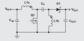
The SEPIC topology consists of an input capacitor, an output capacitor, coupled inductors, a diode, and a power MOSFET. To understand the working of the SEPIC, let’s assume that the switch is first open. In this state, it can be easily seen that the input capacitor Cin is charged at the input voltage. The voltage across the inductor L1b must be the same as Vout and therefore, the voltage across the switch must be Vout+Vin.
When the switch is closed, the capacitor Cp is charged to the input voltage which then charges L1b. Energy is also stored in the inductor L1a from the input during this state. When the switch is opened again, the inductor L1a discharges to the output capacitor via diode and power the load.
The converter’s output voltage can be controlled by adjusting the duty cycle of the MOSFET. SEPICs are mostly controlled by PWM regulator ICs and a microcontroller that drives the gate of the MOSFET according to the sensed voltages. But for compact devices, DC-DC converter ICs are widely used. They consist of integrated MOSFETs, an internal voltage reference for feedback, and are highly efficient.
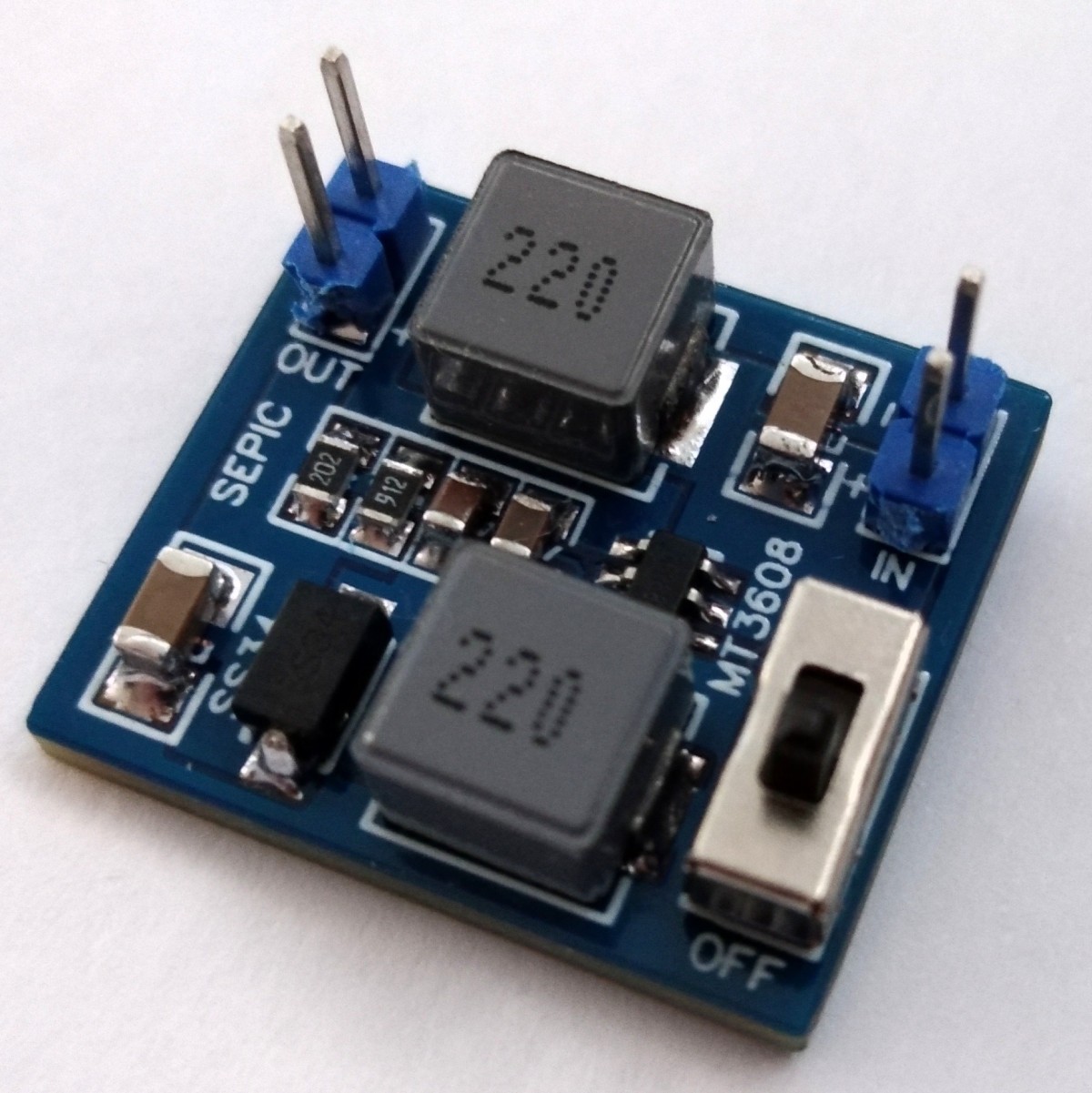
SEPIC PCB based on MT3608
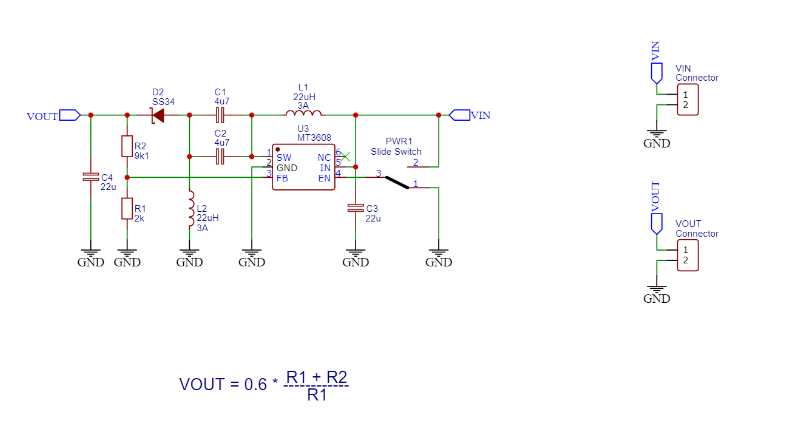
Stefan Wagner from Germany designed a SEPIC PCB based on MT3608 DC-DC converter IC. MT3608 is a very compact boost converter IC that provides up to 97% efficiency and also allows a wide input voltage range. In addition, MT3608 includes under-voltage lockout, current limiting, and thermal overload protection to prevent damage in the event of an output overload. The schematic of the SEPIC design is as follows:
The output voltage is divided by a resistive voltage divider to the FB pin of the IC. The voltage at the FB pin is compared to an internal reference voltage of 0.6V, and the PWM is controlled accordingly.
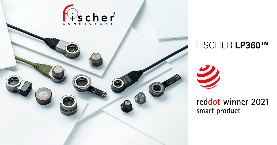
The Red Dot Design Awards stand for outstanding achievements in product design. The jury evaluates thousands of entries each year. For its Fischer LP360™ connectors from the Fischer Freedom™ Series, which have already won numerous industry awards, Fischer Connectors has now been awarded the prestigious Red Dot Award for Product Design in two categories: the “Mobile Phones, Tablets and Wearables” category, and the new “Smart Products” meta-category. The judges praised the connectors’ unique design concept, which makes them both appealing to users and particularly easy to use.
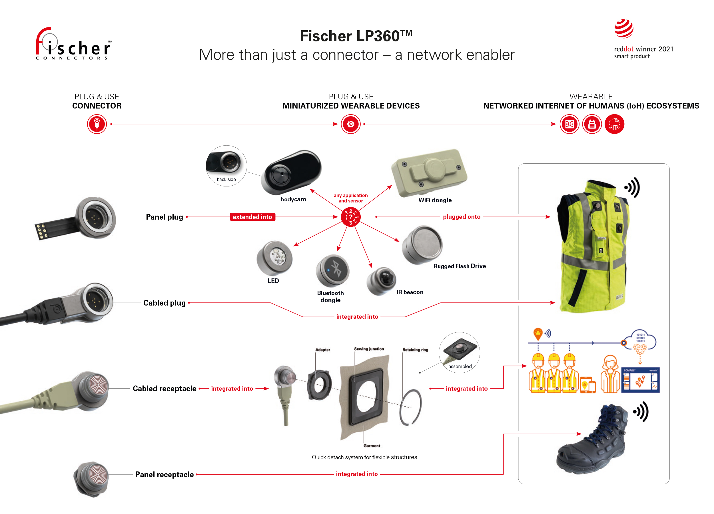
What was rated “smart” in the Fischer LP360TM is the connectivity solution’s multifunctional integration capability and modularity. The new connector is indeed truly multi-talented. It is a miniaturized active device, a fastening mechanism and an electrical signal and power connection all in one.
The rugged, low-profile connector was expanded in 2019 into a versatile technology platform that serves as an enabler for wearables and connected ecosystems in the Internet of Things and of Humans (IoT/IoH). The breakthrough plug-and-use technology benefits both engineers and end-users. Multiple configuration options facilitate application design. The panel plug can easily be extended to multifunctional wearables, such as biometric sensors, communication systems, GPS, lighting and bodycams. These can be snapped quickly and easily onto the cabled receptacle, which is integrated into flexible structures like ready-to-use smart personal protective equipment (PPE) vests. Since the connector has no key code, it can be plugged in any position, optimizing cable routing and power management. Contacts are IP68-sealed with a membrane, ensuring that the connector is fully cleanable. The low-profile design enables easy integration into any application, such as smart work vests. Mobile workers thus benefit from lightweight equipment without cable clutter, faster and more intuitive setup, easy handling and cleaning, reliable connectivity, and fast data transmission for enhanced safety and performance.
These features also convinced the Red Dot Award jury. In the citation for the award in the Smart Products category, the jury said:
“These connectors impress as a miniaturized and, at the same time, versatile technology platform with innovative 360-degree plug-in connectivity.” For the award in the Product Design category, the LP360’s user-friendliness was particularly highlighted: “The LP360 is impressively intuitive to use. It can quickly be inserted into the socket and is integrated into a connected vest, forming a hub.”
Jérôme Dabonneville, CTO and R&D Director of the Fischer Connectors Group, explains:
“Initially the Fischer LP360TM design had to solve users’ pain points in a way that helped unify the connector’s form and function, transforming “how it works”. On that journey, our teams went beyond our heritage as a connector manufacturer and ended up proposing a connectivity solution platform. The Fischer LP360TM connectors are indeed more than just connectors. They are also smart devices which are opening new doors for designing devices, contributing to the development of the Internet of Things, smart electronic ecosystems, as well as wearable technology and its networking and digitalization. We are very honored to receive these two Red Dot Awards as a testimonial of the Fischer Connectors Group’s connectivity solution that goes beyond the connector.”
Jonathan Brossard, CEO of the Fischer Connectors Group:
“At Fischer Connectors, we have always seen ourselves as innovation drivers. The development of the Fischer LP360TM is a real milestone in our company history. We’re very proud that our developers’ outstanding performance has now been honored with two Red Dot Awards. This recognition of our achievement in industrial design by renowned experts is also an incentive for us to continue developing our connectivity solutions in such a way that they contribute to a networked industry and to the connected human”.
The winners of the Red Dot Awards 2021 will be announced during the virtual Red Dot Design Week from June 21-25, 2021. During the entire week, the award winners will be given a digital stage. The event will center on a web special on the Red Dot website. All the award-winning products will be presented there. Moreover, the Red Dot Design Museum in Essen, Germany, will display impressions from its two special exhibitions.
The ARINC 818 video protocol since its inception has gained wide adoption on large aircrafts such as Airbus A350XWB, Boeing 787, KC46A, and many others. ARINC 818 protocol is used to provide point to point, high-speed, low-latency video transmission for mission-critical systems such as cockpit display, video processors, cameras, and IR sensors. Offering high-speed ARINC 818 interfaces in FPGA arises many challenges due to low-latency and synchronous timing requirements for most displays.
iWave Systems, being the leading FPGA design house, offers an extensive portfolio of FPGA IP Cores. And one of the most predominant being ARINC 818 IP. Today, we are excited to announce the successful implementation of iWave’s ARINC 818 IP Core on Microsemi PolarFire FPGA devices. The PolarFire devices offer the highest security, small form factor, flash-based FPGA, that consume 50% low power competing to mid-range FPGA’s.
Key features include:
Fully compliant with ARINC 818-2 standards
Can be used for both transmit and receive applications
Flexible streaming video interface
Configurable ADVB video formats(resolution, pixel type, etc.)
Supports progressive and interlaced video formats
IP parameters can be configured as per customers interface control document(ICD)
Transmission medium – either optical or copper
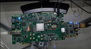
The ARINC 818-2 complaint PolarFire FPGA evaluation kit is suitable for various high-performance applications and functionalities that include communication, military, aviation. With strong competence in FPGA, iWave Systems has demonstrated the seamless integration of iWave’s ARINC 818-2 IP transmitter and receiver functionality on Microsemi’s PolarFire FPGA evaluation kit.
Demo description:
FPGA Platform: Microsemi PolarFire FPGA EVK
FMC card: Multi-video interface Add on FMC card iW-EMELA-PC-01-R1.0
HDMI Monitor: To display the video output
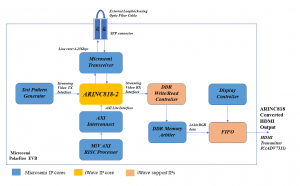
Fig 1.0: System architecture for external loopback testFig 1.2: Demo implementation
Demo: External loopback test
The ARINC 818-2 IP transmitter block receives the video data generated by the internal test pattern generator and converts it into ADVB frames. These ADVB frames are sent out through an FPGA transceiver that is connected to the SFP module. These ADVB frames are looped back to the Rx channel via the SFP module, which is then decoded by the ARINC 818-2 IP receiver block to retrieve the video data and is then displayed on the HDMI monitor.
The ARINC 818 protocol has become the effective standard for high-performance military and avionics video systems, and with this, we help our customers realize their ideas into reality with assured strong and unparalleled FPGA design-to-deployment competence.
iWave Systems has also evaluated ARINC 818 IP Core across a wide range of Xilinx and Intel-based evaluation kits and has successfully licensed ARINC 818 IP to many of our esteemed clients around the world.
iWave Systems presents an extensive portfolio of standard/custom System On Modules, SBC based on Xilinx Zynq & Zynq MPSoC SoC devices, Intel Arria10 & Cyclone V devices, and comprehensive Engineering design services involving embedded hardware, FPGA, and software development in servicing to multiple domains across the globe such as Industrial, Medical, Automotive, IoT and Computer Vision.
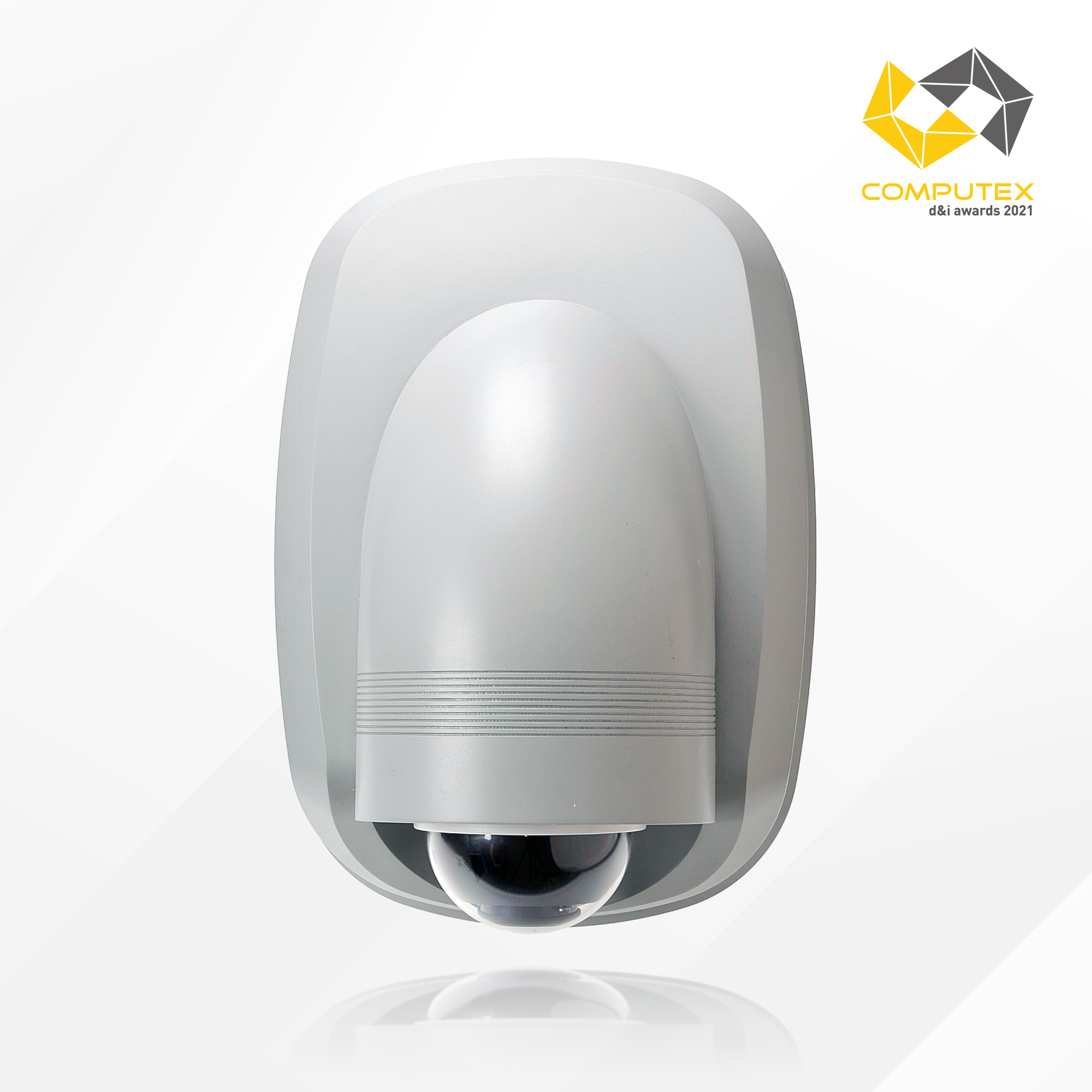
AAEON, the industry leader in AI and IoT network solutions, is proud to receive recognition in the COMPUTEX d&i Awards 2021. The ATLAS Roadside Unit (RSU) is honored with an award, recognized for its innovative design which helps accelerate Smart City deployment.
The COMPUTEX d&i Awards are recognized by the Information Communication Technology industry as a prestigious award promoting and highlighting innovation and driving R&D breakthroughs in the technology field from industry giants to independent up-and-coming developers. Organized by the Taiwan External Trade and Development Council (TAITRA) and the Industrial Technology Research Institute, the COMPUTEX d&i Awards have been held for the past 14 years ahead of COMPUTEX Taipei, Asia’s largest IT trade fair.
The ATLAS Roadside Unit (RSU) is designed to easily deploy and power a wide range of Smart City applications from Intelligent Traffic Management, smart energy management for street lamps and even environmental monitoring for up-to-date weather and road conditions. A powerful solution that is easy to deploy, the ATLAS RSU can help cities quickly set up and take advantage of emerging Smart City technologies.
The ATLAS RSU is designed to mount anywhere, adaptable to any kind of street lamp or wall mounting deployment. It is a completely integrated platform, combining camera, computer, and sensors into a single system, reducing installation complexity. Additionally, it helps to accelerate deployment of Smart City technologies by leveraging Vehicle-to-Everything (V2X), 4G/LTE and 5G cellular communications, and utilizes Intel® technology to bring AI and Edge computing to monitor traffic flow, environmental conditions, and connect with any additional external sensors required.
AAEON provides cities with industry leading service and support, by creating an end-to-end solution with ATLAS RSU. From device to cloud to custom dashboard, AAEON works with city governments and managers to provide the exact level of service and support they need to deploy their Smart City. As each city is unique with differing needs, AAEON is able to meet these needs to deliver the best solution to meet those individual needs.
To learn more about the ATLAS RSU or how AAEON is helping to accelerate Smart City technology, contact your AAEON representative or visit aaeon.com
Nordic Semiconductor has partnered with oemsecrets.com to give away 5 Nordic Thingy:52 compact multi-sensor prototyping platforms. To enter simply follow the link below for your chance to win.
Get extra entries into the giveaway by following us and sharing this on Instagram, LinkedIn, Facebook or Twitter using #oemsecrets or @oemsecrets.
The Nordic Thingy:52™ is an easy-to-use prototyping platform, designed to help in building prototypes and demos, without the need to build hardware or even write firmware. It is built around the nRF52832 Bluetooth 5 SoC.
The key features include:
Supports Bluetooth LE and NFC
User-programmable button and LEDs
Nine-axis motion sensor
10% Discount with Arrow Electronics
Get 10% off Arrow products (exclusions apply) when buying through oemsecrets.com. Simply add the products to the basket and use the link below to find your relevant discount code. See terms & conditions.
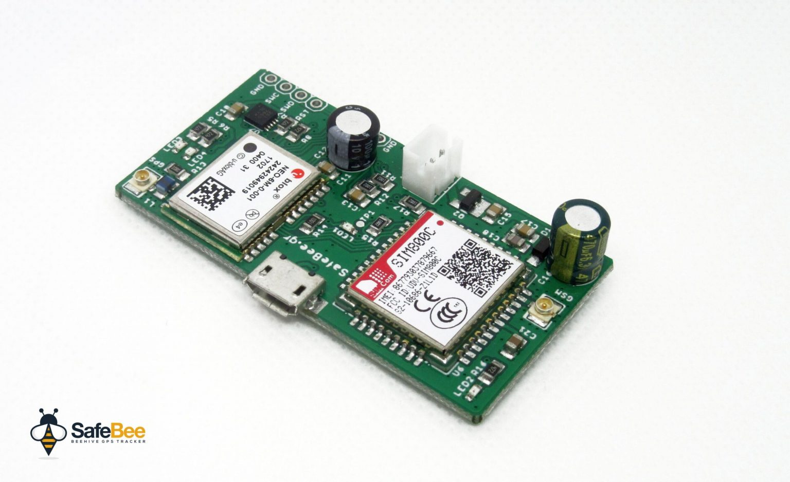
This is an original design of a GPS tracker designed on Elab and it is intended to be used as a security device for beehives, but it is not limited to this. It can be used everywhere a motion-activated GPS tracker is needed, like your car, bike, or even your boat. It is a GPS tracker controlled by simple SMS commands and it is designed for reliability,low power consumption, and easeof use. It features a MEMS accelerometer that is used to intelligently detect movement and once triggered it will power on the GPS module and will try to acquire the current coordinates. The location details will be transmitted to the owner’s smartphone via a simple SMS and then follow update the coordinates at predefined intervals.
Key Features:
Remote management via simple SMS commands
High reliability – no need to babysit the tracker due to crashes and resets
Long battery life – over 1-year standby on a single charge (2500mAh battery)
3-axis high sensitivity MEMS Accelerometer
Intelligent Triggering – it will not be triggered by accidental movement