With the increase in demand for wearable electronic devices, the need for flexible, thin, and compact electronic circuits also arises. Wearable devices and many other sophisticated systems need sensors that can be attached to various kinds of surfaces or substrates. Therefore, it is necessary for the sensors to be flexible and also hold the same electrical property. In addition, there is a constantly growing demand for flexible indicators and displays. The most crucial component of an electronic system is, however, the transistor. There is a lot of research and development ongoing for Thin-Film Transistors (TFTs). These special types of transistors are made by depositing thin films of the semiconductor layer as well as the dielectric layer and metallic contacts on a non-conducting substrate.
Printed Electronics: A Summary
Very thin electronic devices and circuits are part of the printed electronics terminology. Printed Electronics is a new way to manufacture electronic components and circuits. It refers to the process in which printing technology is utilized to produce various electronic circuits, displays, sensors, RFID systems, solar cells, etc. We’re all aware of conductive ink which is an ink that can result in a printed object which conducts electricity. It is created mainly by infusing graphite. Similarly, some well-known technologies for printing electronics are gravure, flexographic, offset, and inkjet printing. Flexographic printing can print the thinnest layers while gravure is the fastest technique for printing electronic circuits.
The printing is based on organic conducting, semiconducting as well as printable organic materials. The printed transistors are fabricated on thin plastic film substrates with various printing processes. Thin-film transistors can also be based on organic semiconductors. The benefit of organic printing is its eco-friendliness.
An Overview of a Research at the Duke University on Fully Recyclable Printed Electronics
The market for printed electronics is constantly growing. The market was predicted to increase to 45 billion USD in 2021. With this, some questions arise like what happens when the printed electronics become waste? Can they be recycled? The silicon-based systems cannot be recycled easily and they just add up to landfills. Similarly, in printed electronics, the use of nanomaterials is a crucial part.
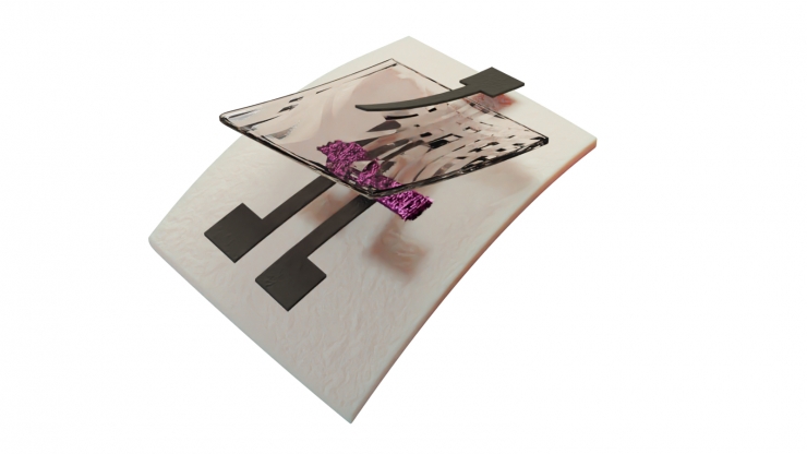
Engineers at the Duke University have successfully developed the world’s first fully recyclable printed electronics. They demonstrated the creation of transistors with three-carbon-based inks. These transistors can be easily printed onto paper or other flexible materials. Carbon nanotubes and graphene inks are used for semiconductors and conductors respectively. The recyclability is due to the use of nanocellulose ink which is derived from wood.
“Nanocellulose is biodegradable and has been used in applications like the packaging for years,” said Aaron Franklin, the Addy Professor of Electrical and Computer Engineering at the Duke University. He further added, “And while people have long known about its potential applications as an insulator in electronics, nobody has figured out how to use it in a printable ink before. That’s one of the keys to making these fully recyclable devices functional.”
The researchers developed ways for suspending crystals of the extracted nanocellulose which will act as an insulator in printed transistors. The team showed that their recyclable printed transistor is well enough for use in a variety of applications, even six months after the initial printing. Further, the recycling process recovers 100% of the materials and the materials lose very little of their properties.
“Recyclable electronics like this aren’t going to go out and replace an entire half-trillion-dollar industry by any means, and we’re certainly nowhere near printing recyclable computer processors,” said Franklin. “But demonstrating these types of new materials and their functionality is hopefully a stepping stone in the right direction for a new type of electronics lifecycle.”
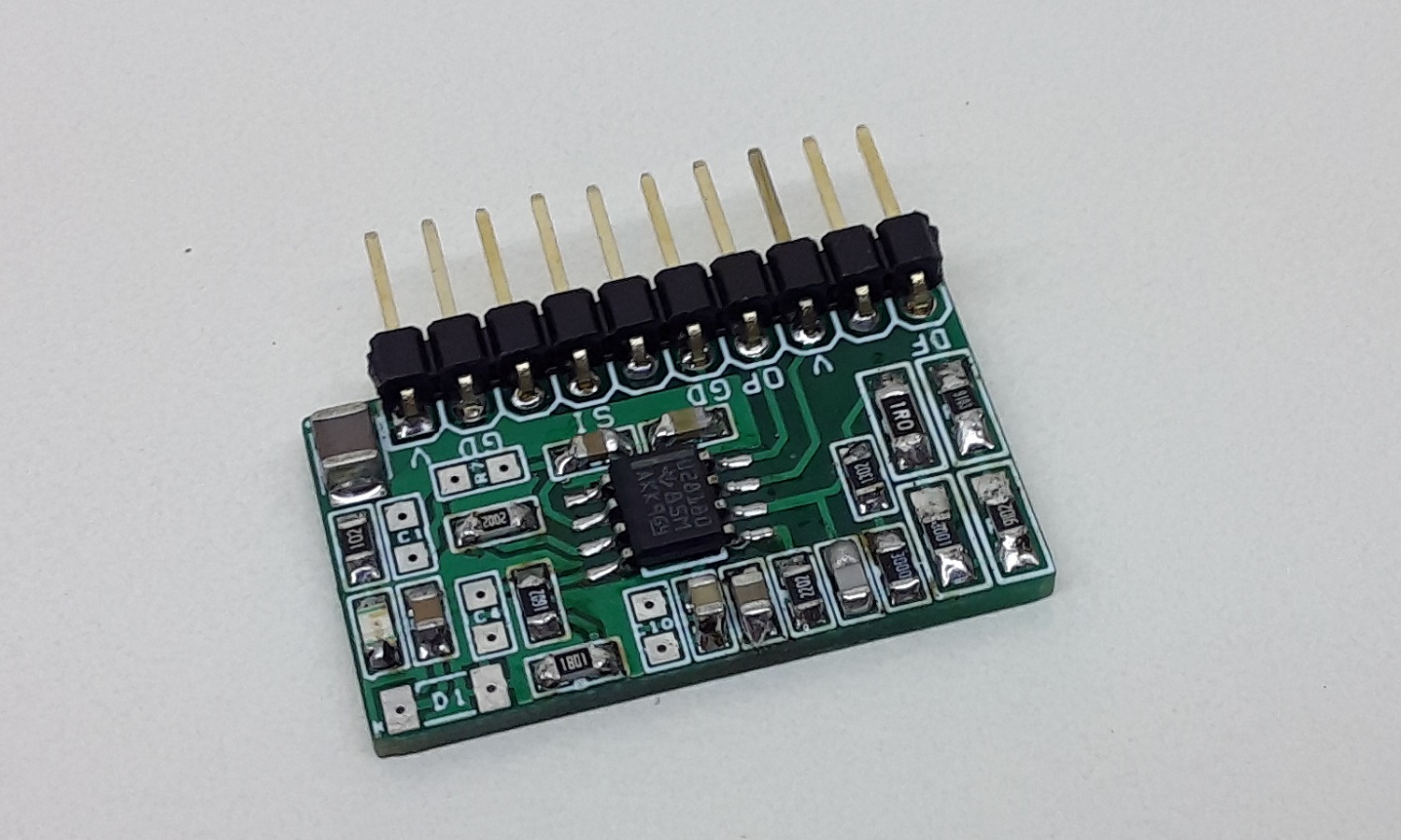
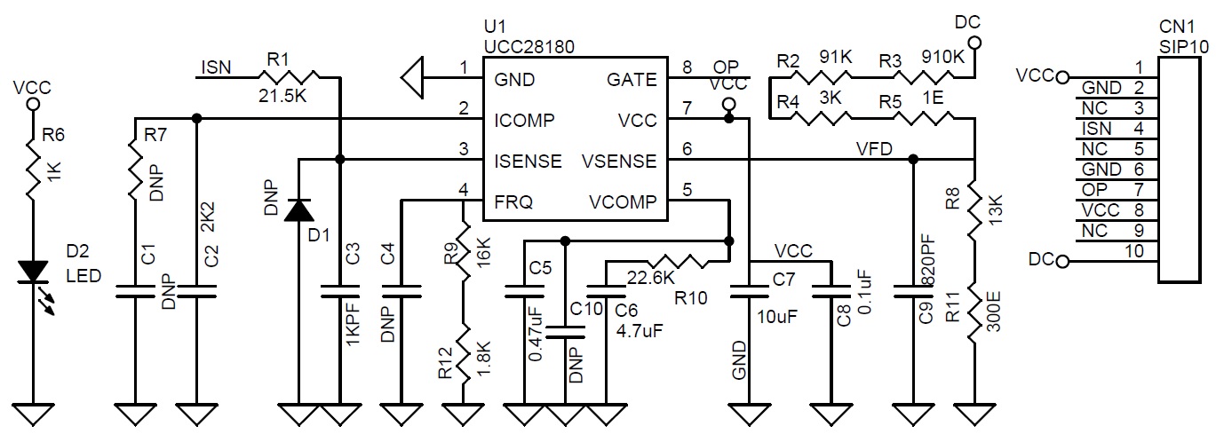
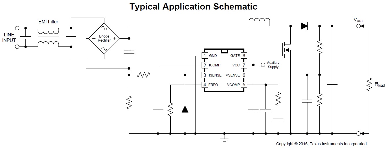
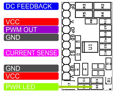
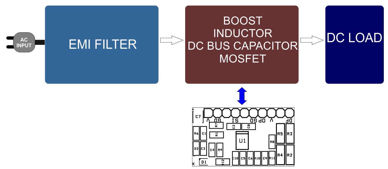
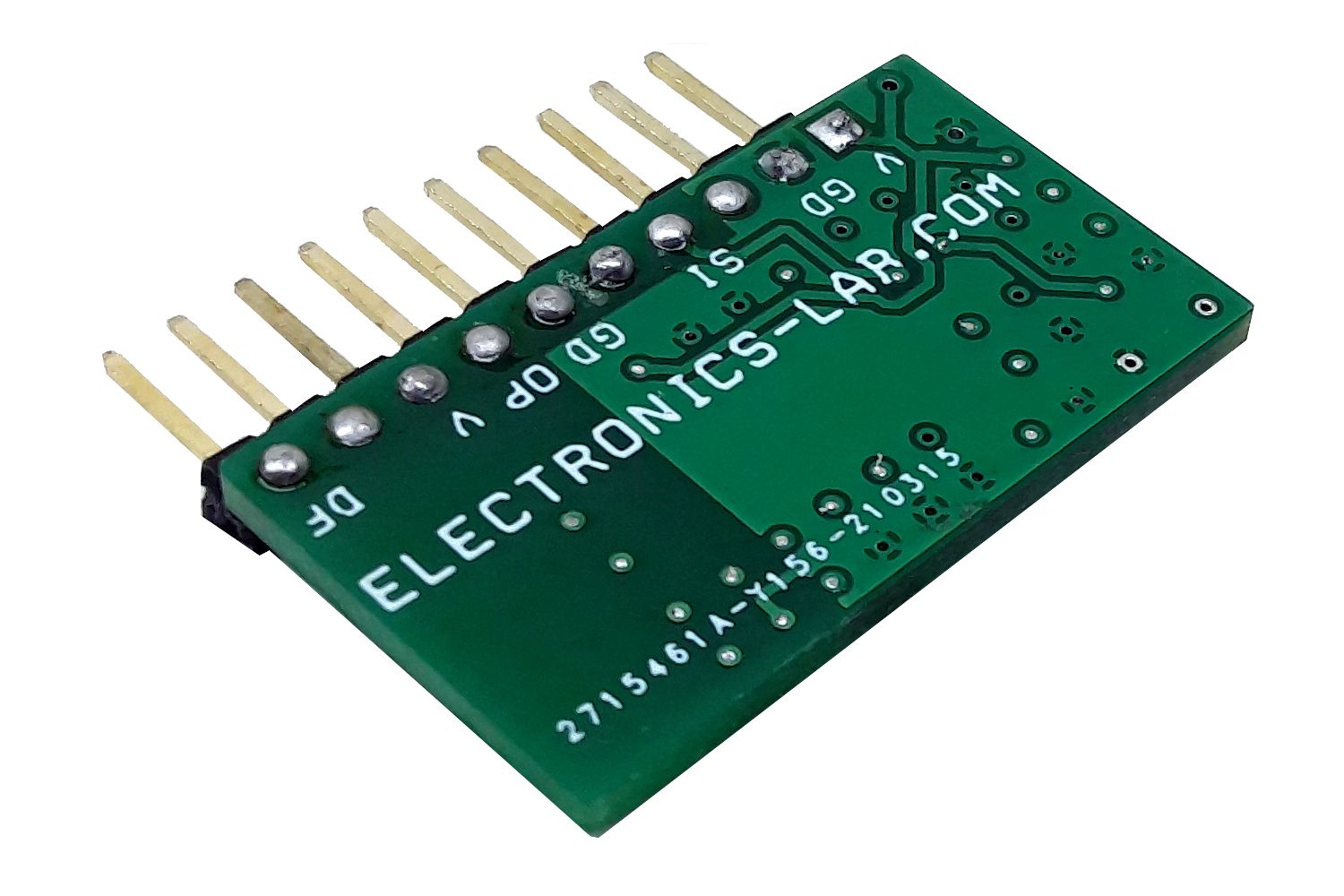
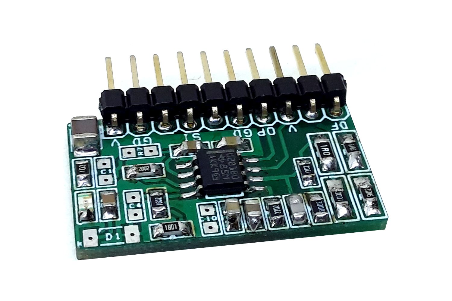
The circuit described here is a simple PFC controller using the UCC28180 chip from Texas instruments. The controller operates under average current mode control at a fixed programmable switching frequency of 116 kHz. Simple external current and voltage loop compensation, along with advanced protection features, make this controller ideal for server and desktop power supplies, industrial power supplies, and white goods. The module is a flexible and easy-to-use, active Power-Factor Correction (PFC) controller that operates under Continuous Conduction Mode (CCM) to achieve high Power Factor, low current distortion, and excellent voltage regulation of boost pre-regulators in AC – DC front-ends. The controller is suitable for universal AC input systems operating in 100-W to few-kW range with the switching frequency programmable between 18 kHz to 250 kHz, to conveniently support both power MOSFET and IGBT switches. An integrated 1.5-A and 2-A (SRC-SNK) peak gate drive output, clamped internally at 15.2 V (typical), enables fast turn-on, turn-off, and easy management of the external power switch without the need for buffer circuits. Low-distortion wave shaping of the input current using average current mode control is achieved without input line sensing, reducing the external component count.
In addition, the controller features reduced current sense thresholds to facilitate the use of small-value shunt resistors for reduced power dissipation, especially important in high-power systems. To enable low current distortion, the controller also features trimmed internal current loop regulation circuits for eliminating associated inaccuracies. The module requires few external components to create a complete PFC Controller. In the future, we will publish few PFC drivers using this module. Refer to the datasheet of UCC28128 to configure the board as per requirement.
Features
Supply 12 to 15V DC
Default Frequency 116Khz (Programable 18Khz to 250Khz Resistor R9, R12)
Average Current Mode PWM Control
NO AC Line Sensing Needed
Soft Over Current and Cycle by Cycle Peak Current Limiting
Voltage Regulation Open Loop Detection
Output Over-Voltage Protection with Hysteresis Recovery
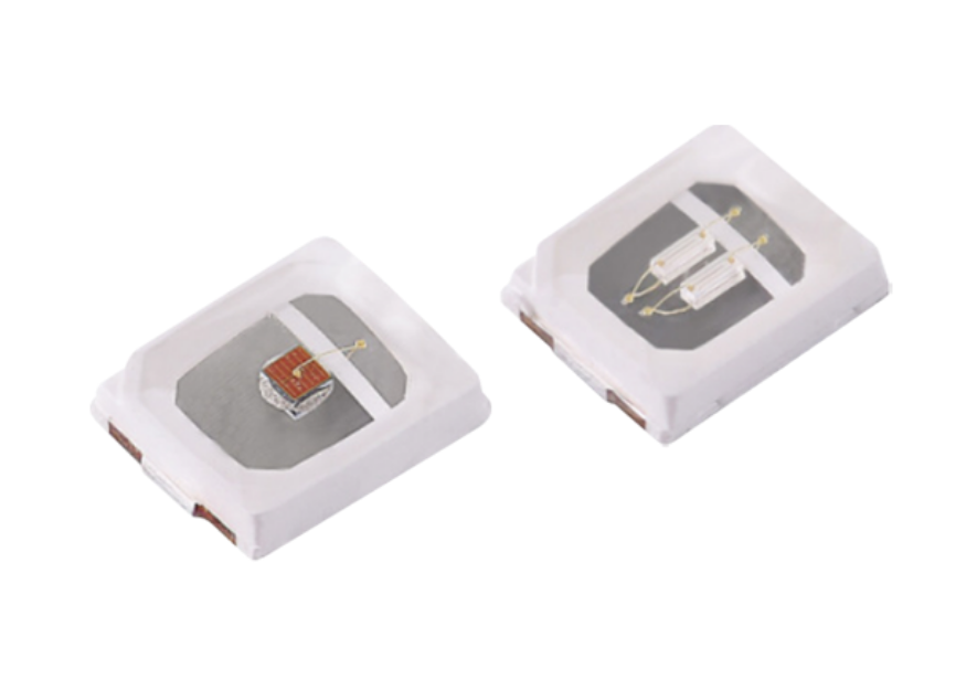
Luminus Devices MP-2835 Mid-Power LEDs are lighting class solutions that are designed to provide high luminous flux output and high current capability. These LEDs operate at 5V reverse voltage (VR) and -40°C to 85°C operating temperature range. The MP-2835 LEDs feature a thermally enhanced package design and are available in compact package sizes. These LEDs are used in applications such as horticulture, architectural, decorative, billboard light, and industrial.
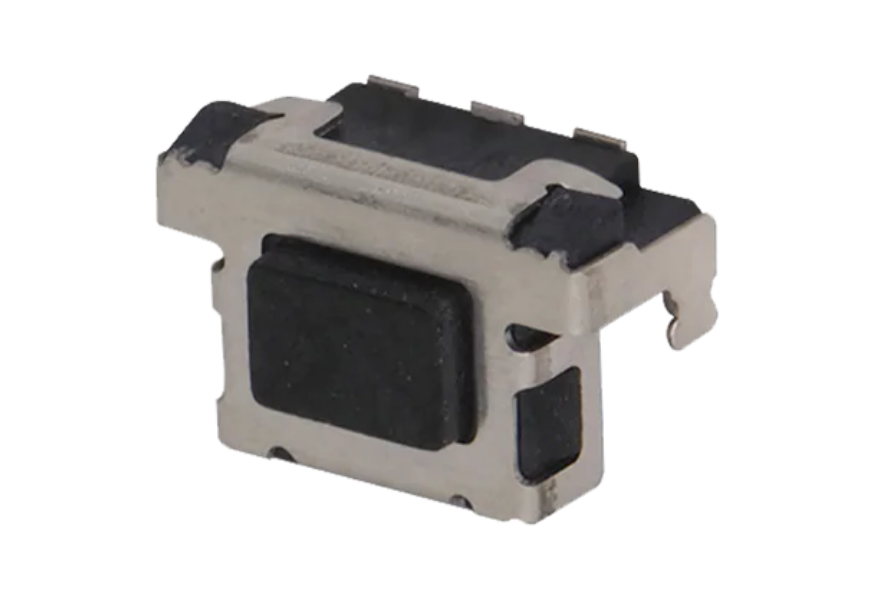
C&K PTS847 switches are 4.6mm x 2.2mm side actuated SMT tactile switches. These normally open SPST momentary switches offer an estimated life of 200k cycles. C&K PTS847 switches offer a variety of configurations, including actuation force (160gf or 350gf), actuator options (hard or soft), and shielding (with or without L shaped shield). These tiny surface mount switches are suitable for a variety of small electronics controls.
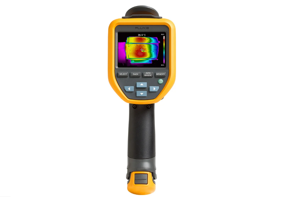
Fluke Electronics’ thermal imagers allow for simplified proactive maintenance
Fluke Electronics’ proactive maintenance (PM) program helps maintenance teams and the bottom line by allowing users to see what is working well or if something is about to break down before that happens. To get started, the TiS55+ and TiS75+ thermal imagers have the features to easily set up image organization and inspection routines.
With the TiS55+ and TiS75+, executing a successful preventative maintenance program will not take long. This system makes a clipboard to record notes for numerous inspections unnecessary. It becomes easier than ever to keep track of what has already been inspected. Save time and improve the reliability of maintenance data by wirelessly syncing measurements using the Fluke Connect system.
Features
Eliminate data-entry errors by saving measurements directly from the tool and associating them with the work order report or asset record
Maximize uptime and make confident maintenance decisions with trustworthy and traceable data
Move away from clipboards or notebooks and multiple spreadsheets with a wireless one-step measurement transfer
Access baseline, historical, and current measurements by asset
Share measurement data using ShareLive™ video calls and emails
The TiS55+ and TiS75+ infrared cameras are part of a growing system of connected test tools and equipment maintenance software
Image sensors are the crucial part of various analog and digital electronic devices such as digital cameras, webcams, camera phones, camera modules, optical mouse devices, medical applications, night vision cameras, thermal cameras, barcode scanners, radar, sonar, and many others. An image sensor is a type of sensor that detects and conveys information used to make images. The information is the variation in light waves. This data of attenuation of the light waves are converted to electrical signals. The signals created are like short bursts of current that carry information. The image sensors mostly use either CCD (Charge Coupled Device) or CMOS technology.
CCD Technology-based Image Sensors
CCDs (Charge Couple Devices) use MOS (Metal-Oxide-Semiconductor) capacitors and CMOS amplifier stage for image sensing. Here, an array of MOS capacitors is employed, each carrying an electric charge corresponding to the light intensity of a pixel. With the help of a control circuit, the charge from one capacitor is transferred to its neighboring capacitor. The process here is similar to the data transfer in shift registers. The charge from the last capacitor in the array is transferred to a charge amplifier. The charge amplifier reads the quantity of that charge and in this way, an image is formed. The CCD-based image sensors are used in high-end broadcast systems where quality is a concern.
CMOS Technology-based Image Sensors
CMOS image sensors are also based on MOS technology like the CCD technology. But in this technology, a photodiode, and a MOSFET is used for each pixel. This allows the pixel data to be amplified individually. With this approach, the CMOS image sensors achieve a higher data rate than CCDs. Further, noise occurrence is also low in CMOS technology. In addition, CMOS image sensors cost less to produce and are preferred in compact devices due to their low power consumption.
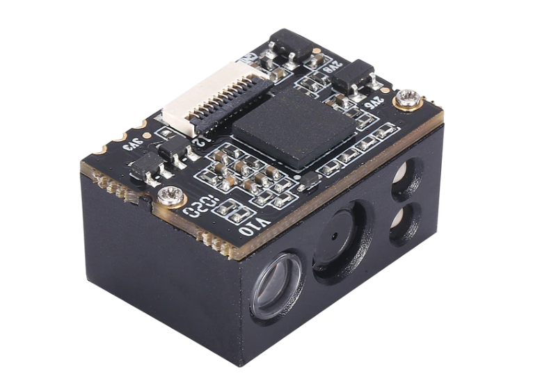
About the 2D CMOS PDF417 Barcode Scanner module
2D CMOS barcode scanners are very popular nowadays due to their high quality, range, and low price. 2D barcode scanners can scan 1D barcodes as well as 2D codes such as QRCodes and data matrices. 2D CMOS PDF417 scanner module is a very compact auto-sensing barcode scanner module that supports the TTL interface. It is specially designed for PDF417. PDF417 is a stacked linear barcode format used in a variety of applications such as transport, identification cards, and inventory management. “PDF” stands for Portable Data File. The “417” signifies that each pattern in the code consists of 4 bars and spaces in a pattern that is 17 units (modules) long [1].
It has the following features:
Specially Designed for PDF417
CMOS image sensor,reads 1D & 2D barcodes.
No driver, plug and play.
Supporting TTL interface.
A wide-angle lens design that scans a large area.
Super scanning and decoding ability, can read incomplete and fuzzy codes.
The scanner reads 2D & 1D barcodes printed. on labels or displayed on device screens.
Mini size and lightweight easy to be integrated into various solutions such as kiosks flow line. medical equipment. ticketing machines, PDA. vending machines, and many more.
The USB Bluetooth dongles are quite popular nowadays. Most wireless computer mouse comes with a USB Bluetooth dongle which enables wireless communications to your PC. A USB Bluetooth dongle is a very quick and inexpensive means to allow Bluetooth communications onto your computer. To use the dongle, you simply need to plug it in the USB port of your PC and any Bluetooth peripheral devices will be able to communicate with your PC. You can connect various peripherals like cellphones, printers, PDAs, Wireless earphones, wireless keyboards, etc.
A USB Bluetooth dongle has a built-in antenna that has a range of 2 to 100 meters and operates on a 2.4GHz frequency band. The Bluetooth dongles are used for various applications like transferring videos, photos, and in many other applications like this.
Bluetooth Low Energy
Bluetooth Low Energy (BLE) is a wireless personal area network technology independent of the classic Bluetooth and has distinct compatibility. The original BLE specifications were developed by Nokia in 2006 under the name Wibree and are intended for applications in fitness products, healthcare, security, and home entertainment. BLE features a significant reduction in power consumption and also cost as compared to standard Bluetooth. Very low-power devices which operate for months or years on a button cell uses BLE for communication. However, a similar communication range is maintained and the same 2.4GHz frequency band is used.
As mentioned earlier, BLE’s compatibility is different from the basic Bluetooth protocol but BR/EDR and LE systems are permitted.
Bluetooth 5.0
Bluetooth 5.0 is the latest Bluetooth standard in the industry. Bluetooth 5.0 supported devices can transfer data at up to 2Mbps speed which is twice the speed of Bluetooth 4.2. In addition, the range is extended up to 260 feet (if no walls interfere). BLE 5.0 will have a big impact on smart home systems and other IoT devices as per the experts. Low energy, increased range, and increased speed means that the devices can switch over from Wi-Fi.
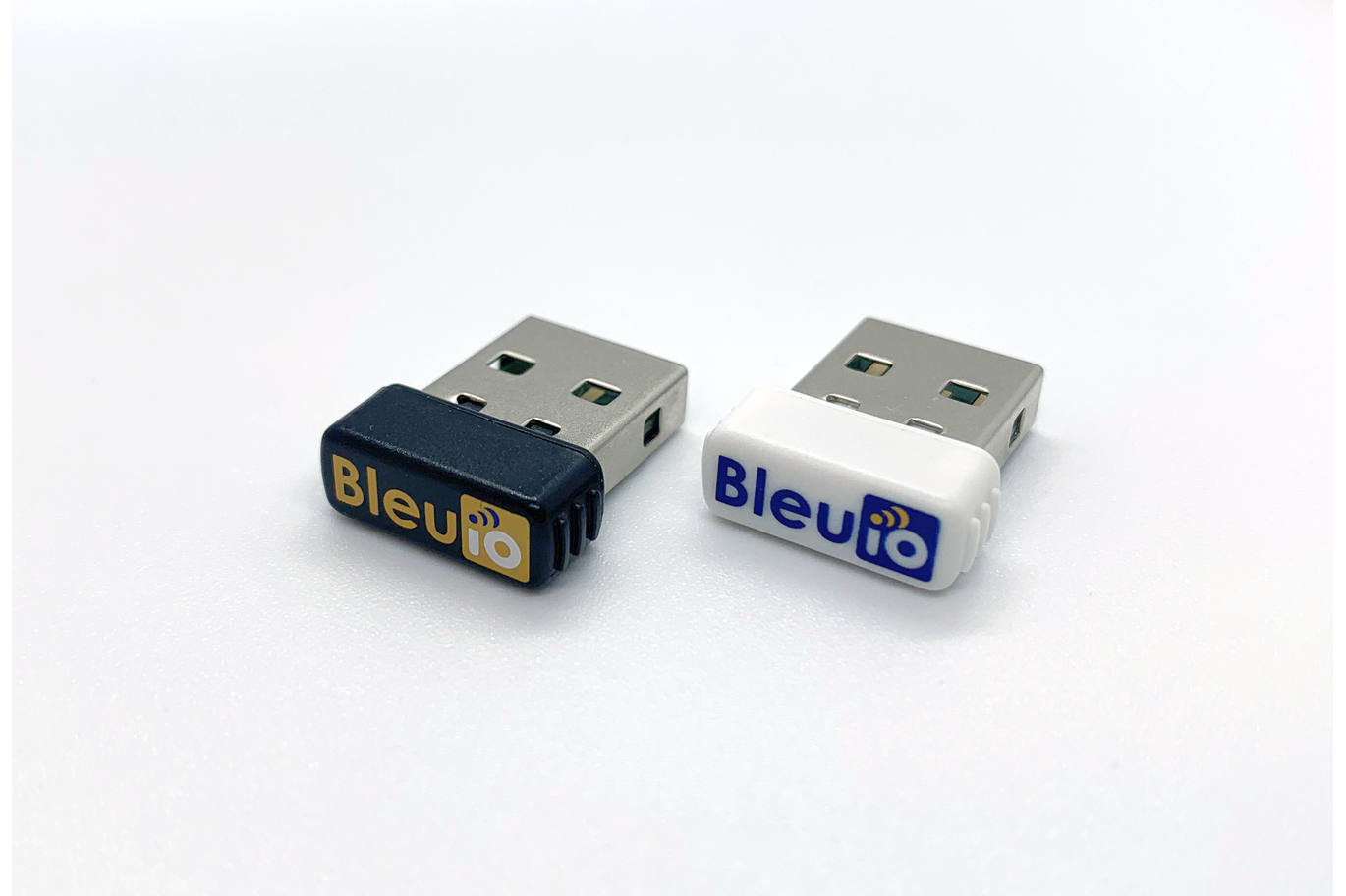
About BleuIO
BleuIO is a Bluetooth Low Energy USB dongle that can support BLE 5.0 devices. It can be used to create new BLE 5.0 applications in the fastest and easiest way. To use it, you just need to utilize the AT commands already available on the device. It is built around Dialog Semiconductor’s latest Bluetooth chip DA14683. The chip supports Bluetooth 5.0 and Bluetooth Mesh. Its flexible architecture ensures plenty of processing capacity when needed and goes in power-saving mode when there is no need. It allows multi-sensor arrays and also has extensive memory capacity. In a nutshell, the chip is a very integrated solution providing the benefits of MCU and Bluetooth compatibility on a single chip.
The BleuIO USB adapter comes with the following features:
Compatible with Windows 10, macOS, and Linux.
One can update the firmware or flash their applications with the integrated bootloader.
Low Energy
Just use the AT commands already on the device.
Custom settings can be stored on flash memory or OTP
The JavaScript and Python libraries for BleuIO are available for software development support.
The rectifier is an electrical circuit that converts alternating current into direct current. As discussed in the previous article, the half-wave rectifier converts only the half-cycles of the alternating current either positive or negative depending upon the orientation of the diode. It was also discussed that the efficiency of the half-wave rectifier is less as it utilizes only half-cycles and other halves are blocked/ not present to the output. Moreover, the capacitor filter was used to eliminate ripples and to smooth the output signal. In a half-wave rectifier, the ripple frequency equals the input frequency. These half-wave rectifiers are used in low-power and low-cost power supply circuits.
The efficiency of the rectifier can be improved by utilizing both cycles of input alternating current. The circuit which utilizes both half-cycles to convert alternating current to direct current is termed a full-wave rectifier. The full-wave rectifiers are more efficient compared to half-wave rectifiers and use more than one diode in the circuit.
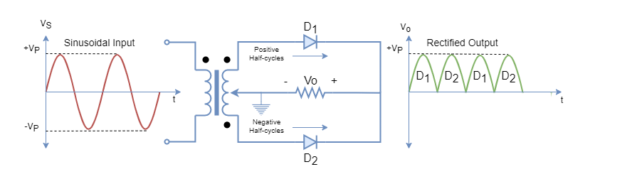
Full-Wave Rectifier Circuit using center-tapped Transformer
The transformer having split secondary winding with the center-tap connected to the resistive load through two diodes. The transformer usually produces current with a 180-degree phase difference in the secondary winding depending on the dot location on the windings.
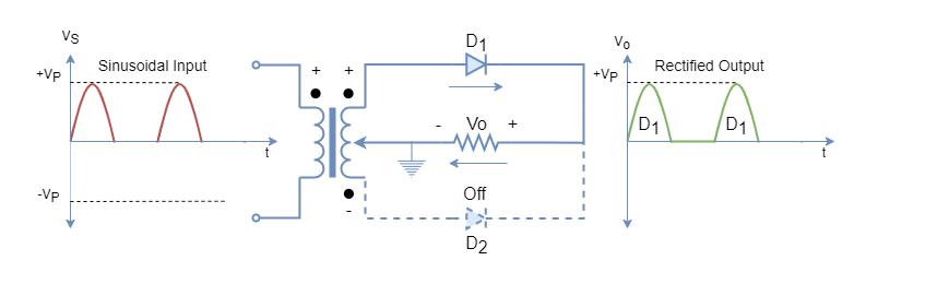
In the above figure-1, the full-wave rectifier using a center-tap transformer is shown. A sinusoidal wave applied to the primary of the center tap transformer is transformed into the secondary winding and voltage potential is developed on the secondary side. The potential developed in the secondary alternates every half cycle. The output of the full-wave rectifier has a time period half of the input or has a frequency double to that of the input signal.
The rectification process is explained for each half-cycle.
During the first half-cycle, the potential developed forward biases D1 diode and reverse biases diode D2. The positive half-cycle passes through the D1 diode and develops the voltage across the load resistor as shown in figure-2. The current direction through the load resistor and the voltage polarity across it, are to be observed and should remain the same during the negative half-cycle.
Figure 2: Full-wave Rectifier Center-tap transformer during positive half-cycles
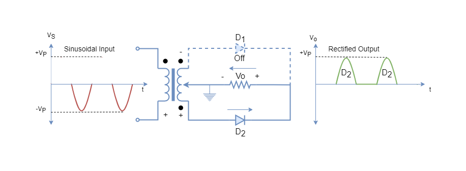
During the second half-cycle, the voltage polarity across secondary winding is shown in figure-3 which is due to reversal of polarity across the primary winding. Under this polarity, the D2 diode is forward biased and the D1 diode is reverse biased. Hence, the D2 diode allows the current to flow through the load resistor whilst the D1 diode remains off during this half-cycle. The current direction through load resistor and voltage polarity across it remains the same as observed during the first half-cycle. This arrangement of diodes with a center-tap transformer leads to a uni-directional current flow through the diode. The rectification of alternating current takes place during both half-cycles i.e. for the whole time period of a sinusoidal signal.
Figure 3: Full-wave Rectifier Center-tap transformer during negative half-cycles
The rectification process continues, similarly, by alternating the current flow through diodes D1 and D2 for the approaching cycles.
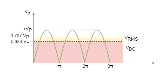
Figure 4: Full-Rectified Sinusoidal Wave
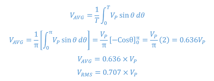
The average of the full-rectified sinusoidal wave is given by:
The average output of the half-wave rectifier, as seen in the previous article, is 0.318 times the peak voltage. But in full-wave rectification, the average output has doubled and due to which the average power delivered has also quadrupled. Hence, leading to a more efficient rectification process as compared to half-wave rectification.
Diode Bridge Rectifier
The transformers having a center-tap secondary winding are more costly and larger in size due to the presence of two windings on the secondary side. Because of this, in power supplies, mostly signal winding transformers are used and a special diode bridging is used to perform full-wave rectification. The diode bridge can be made using four similar diodes or a complete off-the-shelf diode bridge package can be obtained to perform full-wave rectification. The diode bridges are available in different ratings and specifications to fit into different applications and circuit designs.
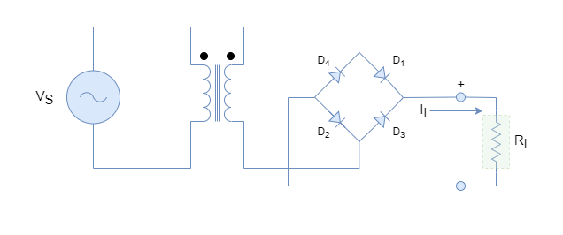
Figure 5: A Simple Bridge Full-Wave Rectifier
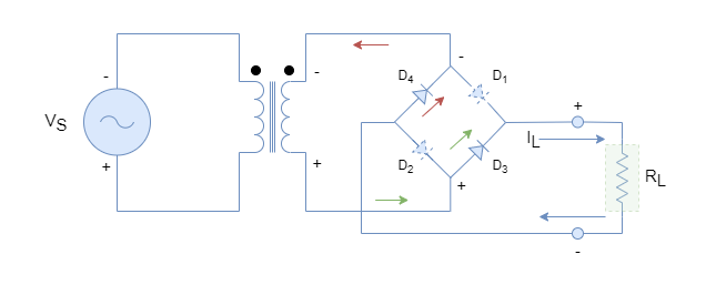
A simple diode bridge full-wave rectifier is shown in figure-5 and four power diodes are used here instead of two diodes in the center-tap transformer. During the first half-cycle, the voltage polarity across the diode bridge is shown in figure-6 which makes the diodes D1 and D2 forward biased. The other half of the bridge i.e. diodes D3 and D4 remain in off condition. This biasing arrangement of the bridge causes the flow of current through the load and a voltage appears across it. The direction of current and voltage polarity across the load is depicted in figure-6.
Figure 6: Bridge Full-Wave Rectifier during first half-cycle
Similarly, for the next cycle, the polarity reverses due to alternating sinusoidal source and voltage across Diode Bridge is shown in figure-7. The voltage polarity makes diodes D3 and D4 forward bias this time whilst diodes D1 and D2 remain off. The direction of current through the load and voltage polarity across it, remains unchanged which means even after reversal of polarity of input sinusoidal wave the polarity across the load remains unchanged.
Figure 7: Bridge Full-Wave Rectifier during second half-cycle
The diode bridge circuit performs full-rectification of successive alternating cycles. The drawback of the bridge rectifier compared to the center-tap transformer is that it uses two diodes at a time for rectification which causes double forward voltage drops.
Full-Wave Rectification Example
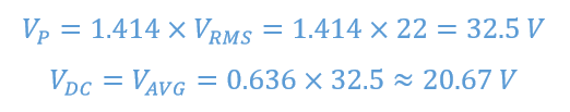
The power supply circuit of the previous article using a half-wave rectifier is used here to compare the results. The voltage source of 220VRMS with 100:1 transformer was used to supply a load of 1 kΩ Using bridge full-wave rectifier:
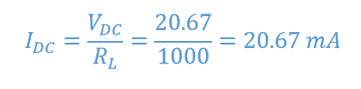
An approximate 20 VDC appears across (forward diode voltage drops are ignored to keep things simple) the load and the current flow through 1 kΩ load is:
The power delivered to the load using a full-wave bridge rectifier:
The full-wave rectifier delivers twice the voltage and quadruple power to the load as compared to the half-wave rectifier. It makes the full-wave rectifier more efficient and for the same voltage power supply a smaller transformer can be utilized compared to using a half-wave rectifier. For example, using a half-wave rectifier, a 10:1 ratio transformer is used to supply approx. 10 VDC to the load when input is 220VRMS. However, a 5:1 ratio transformer can be utilized to deliver the same load voltage using a full-wave bridge rectifier.
Ripples and Filtering Capacitor
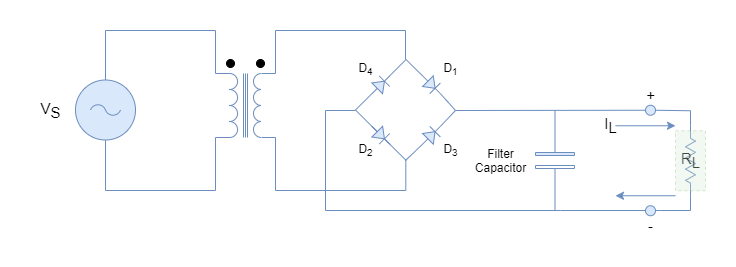
However, an increase in efficiency comes at the cost of ripples which are doubled compared to the half-wave rectifiers. The increase in ripples is due to an increase in frequency which has doubled. The ripples are undesirable elements of any electronic circuit and the output of power supplies can be smoothed using a filtering capacitor. The peak rectifier circuit with capacitor filter is shown in figure-8.
Figure 8: Bridge Full-Wave Rectifier with capacitor filter
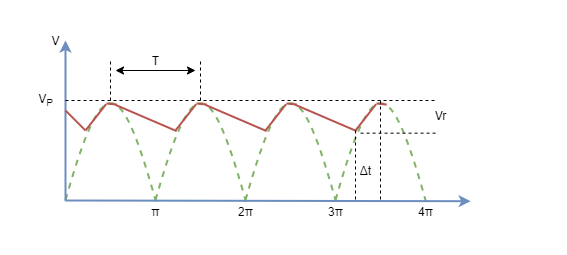
The capacitor acts as storage or reservoir and supplies the load during the OFF period. The value of the capacitor should be large enough so that its time constant (RC) >> time period of the sinusoidal signal. The capacitor charges when the voltage is increasing up to the peak voltage and then it starts discharging by supplying current to the load. The capacitor keeps supplying the load until the next cycle when the voltage starts increasing again. For each cycle capacitor charges and discharges when voltage is increasing and decreasing, respectively. The during the conduction period (Δt), diodes supply the load and charges the capacitor.
Figure 9: Output of Full-Wave Rectifier with capacitor filter
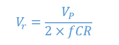
The ripple voltage for a full-wave rectifier is given by the following formula and note that ripple frequency has doubled as compared to half-wave rectifier:
For example, if the desired ripple voltage is 1V for the above example then the value of the capacitor filter is:
So, a capacitor of 325uF is required to have a ripple voltage of 1 V for a bridge rectifier power supply given in the above example.
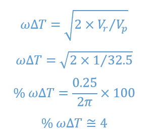
The diode conduction period can be approximated by the following formula:
The diodes will conduct during only 4% of the total period and the rest of the period load will be supplied by the capacitor.
The full-wave rectifiers using bridge diodes are mostly used in power supplies and rectifiers. The drawbacks are the use of two diodes and an increase in ripples. Both of these factors could lead to distortions and harmonics in circuits.
Conclusion
The full-wave rectifiers are most commonly used in the rectification process because they are more efficient compared to half-wave rectifiers.
The full-wave rectifiers can be constructed by using a center-tap transformer or bridge diodes. The center-tap rectifier used a single diode for conduction whereas the bridge-diode two diodes for conduction.
The center-tap full-wave rectifier uses a two-winding transformer increasing the size and cost. Whilst, bridge-diode rectifier uses two diodes for rectification at a time i.e. double forward voltage drop and addition of non-linear device.
The average voltage or DC voltage delivered by a full-wave rectifier is 0.636 times the peak voltage which is twice the voltage delivered by the half-wave rectifier. Ultimately, the power delivered becomes quadrupled.
The ripple factor is double in the full-wave rectifier because of the double frequency.
The ripples can be reduced using a capacitor filter and the time constant of the filter capacitor should be large enough so that it should not completely discharge during the supply period.
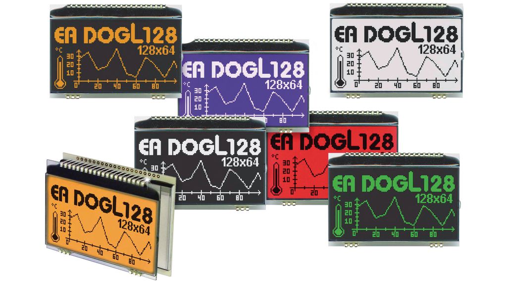
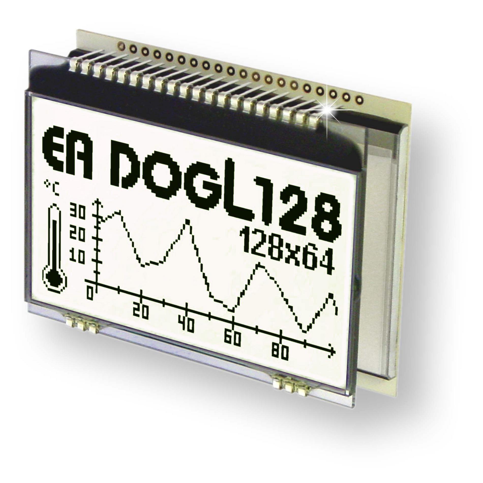
EA Display Visions’ chip-on-glass 128 x 64 graphic LCD is compact, low-power, and pin-connected
EA Display Visions’ DOGL128 series 2.8″ graphic LCDs are available in FSTN positive transflective, STN positive transmissive, STN negative transmissive, FSTN negative transmissive, and STN positive reflective versions. These displays have a 2.54 mm pitch and can be soldered directly or plugged into socket strips. Therefore, cumbersome gluing procedures, the need for designing a special mounting device, and error-prone cable connections that may lose contact are no longer a concern.
The extremely efficient ratio of external dimensions to the active display area helps in designing very compact devices. Furthermore, its low power use (single supply 2.5 V to 3.3 V (typically 250 µA)) makes it ideal for handheld applications.
The EA 9780-4USB development board and free windows simulator are all that users require to evaluate pin-connected chip-on-glass LCDs with and without backlight. Simply plug the 2.54 mm connector pins of the display into the socket strips of the development board. Proprietary hardware or software development is not required, and decisions can be made quickly at a minimum expense.
Features
High-contrast LCD supertwist display (STN and FSTN) with 15 µm dot-gap
Optional LED backlights in various colors
128 x 64 pixels (corresponds to 8 x 21 characters or 4 x 16 large characters)
ST7565R controller with SPI (4-wire) interface
Power supply: single supply 3.0 V to 3.3 V (typically 320 µA)
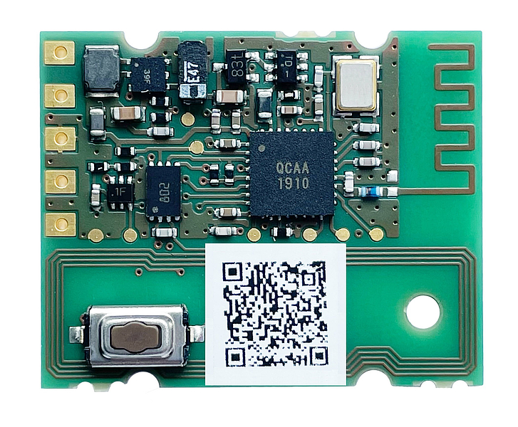
EnOcean, the world’s leading developer of energy harvesting wireless technology, is presenting the PTM 535BZ module, the latest addition to its range of transmitter modules wireless technology for battery-free switch applications. In addition to the already established PTM 535 for the EnOcean wireless standard and PTM 535Z for Zigbee applications, PTM 535BZ is the first module that offers a combination of supported wireless standards in the 2.4 GHz radio band. In conjunction with the EnOcean ECO 200 harvester, PTM 535BZ enables the realization of energy harvesting wireless switches communicating based on Bluetooth Low Energy (BLE) or Zigbee Green Power (ZGP) radio standards. Thanks to the integrated Near Field Communication (NFC) interface, it is easy to switch between the two radio standards depending on the application.
Combined radio standards and NFC for an easy integration
With the new PTM 535BZ module, EnOcean is setting a new standard among battery-free and wireless radio transmitter modules. Until now, energy harvesting modules were designed to use only one radio protocol – EnOcean, Bluetooth or Zigbee Green Power – for data transmission. The newly developed PTM 535BZ is the first module that integrates the two 2.4 GHz protocols BLE and ZGP into one product. This gives users the option of selecting one of these two protocols for transmission depending on their needs. On top, PTM 535BZ is also the first module from the product range to be equipped with an NFC interface; a technical challenge due to the very small form factor. The use of NFC makes configuration much easier and also saves valuable time during installation. It also allows selecting between BLE and ZGP radio protocol and defining all configuration parameters using an NFC-enabled smartphone or, alternatively, a PC with an NFC reader.
“We want to support our customers as best we can with new developments and make the integration and commissioning of our products as simple as possible,” says Matthias Kassner, Vice President Product Marketing, EnOcean GmbH. “The fact that the module supports two wireless standards means that the same end product can be used in various applications. This saves customers not only time but also costs, both being important factors when choosing a product.”
Uniform form factor
As with the existing PTM 535 models for the EnOcean radio standard and PTM 535Z for ZGP, EnOcean is again relying on the same form factor for PTM 535BZ. This offers customers a fast integration into already existing mechanical designs. At the same time, there are almost no limits to the possible radio switching applications due to wireless and battery-free operation and the worldwide usability of 2.4 GHz radio solutions. These include stop buttons in public buses, mechanical door and window sensors or even mini switches for the private home, e.g. to switch household appliances on and off.