Bosch BMP384 Pressure Sensor

Bosch BMP384 Pressure Sensor offers a 1.2V to 3.6V supply voltage range and comes in a 2mm x 2mm x 1mm³ package. This sensor has a gel-filled cavity that allows higher robustness against liquids, water, and other chemicals. The BMP384 sensor is compatible for use with other Bosch Sensortec sensors, including the BMI088 for better performance. The small footprint of this sensor allows for outstanding design flexibility, and makes this a single package solution that can be easily integrated into existing and upcoming devices for smart homes, industrial products, and wearables.

In addition to the interrupt functionality that provides simple access to data and storage, the BMP384 sensor includes FIFO functionality that improves ease of use while reducing power consumption of the overall device system during full operation. Bosch BMP384 Pressure Sensor is ideal for applications of water-level detection and for precise differential barometric pressure measurement.

Specifications

  • Low noise, 24-bit
  • 1.2V to 3.6V supply voltage
  • I2C and SPI interface
  • ±50Pa absolute accuracy rating
  • 200Hz maximum sampling rate
  • 300… 1250hPa operation range
  • 2mm x 2mm x 1mm³ package

more information: https://www.bosch-sensortec.com/products/environmental-sensors/pressure-sensors/bmp384/

Nexperia Silicon Germanium (SiGe) rectifiers offer Cutting-edge high efficiency

Nexperia’s SiGe rectifiers combine the high efficiency of Schottky rectifiers with the thermal stability of fast recovery diodes. Targeting automotive, server markets, and communications infrastructure, the AEC-Q101 compliant rectifiers are of particular benefit in high-temperature applications. These extremely low leakage devices allow an extended safe-operating area with no thermal runaway up to 175 °C. And, at the same time, offer significant room to optimize your design towards higher efficiency.

Nexperia has developed this new rectifier technology based on silicon-germanium (SiGe) for applications in the 100-200V range. Furthermore, they have been developing SiGe rectifier technology in recent years, and already have several patents for the process which address the apparently conflicting demands for high efficiency and high-temperature operation.

Key features

  • VR of 120 V, 150 V, 200 V
  • IR of 1, 2, 3 A
  • Low forward voltage and low Qrr
  • Extremely low leakage current of < 1nA
  • Thermal stability up to 175 °C Tj
  • Fast and smooth switching
  • Low parasitic capacitance
  • AEC-Q101 qualified
  • Space-saving, rugged CFP packaging

more information: https://www.nexperia.com/products/diodes/silicon-germanium-sige-rectifiers/

Diodes’ AL5810Q 60 V adjustable current up to 200 mA linear LED driver offers excellent stability

Diodes Incorporated introduces the AL5810Q, an automotive AEC-Q100 linear LED driver offering an excellent temperature and voltage-current stability with output-adjustable handling capability. The device simplifies the design of LED drivers by setting the LED current with an external resistor using standard value resistors. The AL5810Q has an open-drain output that can swing from 2.0 V up to 60 V supply voltage enabling it to drive long LED chains for high side or low side LED strings. Its low 0.5 VRSET pin is outside of the LED current path and can maintain current accuracy while minimizing the required overheads to regulate the LED current reducing power dissipation. It makes it ideal for driving LEDs up to 200 mA. The AL5810Q is available in the wettable flank W-DFN2020-3/SWP (Type A) package (2 mm x 2 mm), power dissipation (PD) up to 2 W, and has been qualified to AEC-Q100 Grade-2 with automotive compliant supporting PPAPs available.

Features

  • AEC-Q100 Grade-2 qualified
  • Wide input voltage range: 2.0 V to 60 V
  • Low reference voltage: VRSET equals 0.5 V
  • Overtemperature shutdown
  • Ambient temperature range: -40°C to +105°C
  • Adjustable sink or source LED current up to 200 mA
  • ±5% LED current tolerance at room temperature
  • Parallel devices to increase regulated current
  • Lead-free and RoHS compliant
  • Halogen- and antimony-free
  • Available in a wettable W-DFN2020-3/SWP (Type A) (2 mm x 2 mm) PD up to 2 W

more information: https://www.diodes.com/part/view/AL5810Q

Understanding The Ways to Debug Your Raspberry Pi Pico Development Board

If you want to debug any microcontroller, it can be tricky at times. But with the newly launched Raspberry Pi Pico, we have several options to debug the board. It is now possible to use one Raspberry Pi Pico to debug another Raspberry Pi Pico using the ‘Picoprobe’ application or the traditional way of using SWD protocol.

It is always difficult to figure out what is not working. However, Pico comes with three pins for debugging using the Serial Wire Debug (SWD) protocol. To debug a binary program, you need to build a debug version of the binary and get some additional tools.

The above reference image shows the wiring of Raspberry Pi 4 with Pico board. Connect the SWD port directly to the Raspberry Pi to maintain the signal strength. For more information on this method, refer to “Chapter 5” of the “Getting Started with Raspberry Pi Pico” guide.

What makes Pico debugging different is the additional approach of using one RPi Pico to debug another. Even if you use platforms like Windows, Mac, and Linux, you can still use the ‘Picoprobe’ application. This application allows a Raspberry Pi Pico to act as a USB to SWD and UART converter.

“This interface allows you to add up to four breakpoints and two watchpoints. This gives you more control over how your program runs as you develop software.”

If you plan to try the new approach, the UF2 binary file of ‘Picoprobe’ is available to download on the getting started page. To interface both the Raspberry Pi Pico, use the following reference image. Connect the VSYS pin of both the Raspberry Pi Picos to power them.

If you are using the Windows platform, note that you need to install the ‘Picoprobe’ driver for which details are provided in the “Getting Started with Raspberry Pi Pico” guide. This $4 board has provided everything you can ever expect from a microcontroller with PIOs and support for powerful addons.

Note: All the images are taken from the official Raspberry Pi guide.

nRF91 Based cellular-IoT Tracker For Your Blockchain-Based Applications

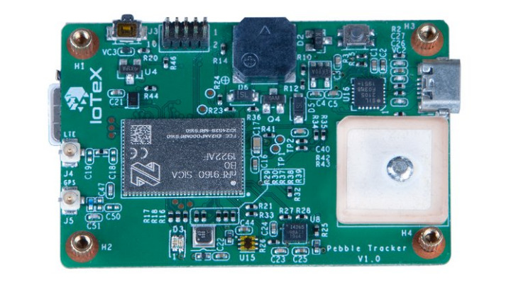
IoTeX has launched a campaign on crowdsupply for Pebble Tracker, which is a secure, battery-operated, cellular-IoT prototyping platform designed for blockchain-based applications. Pebble Tracker is based on Nordic Semiconductor’s latest low-power nRF9160 System-in-Package (SiP), and it is powered by open-source firmware. Pebble Tracker enables GPS support, a host of rich sensors, NB-IoT/LTE-M connectivity, and advanced security features which makes it suitable for sophisticated logistical applications where trust is necessary.  The cellular IoT prototyping platform as well as the IoTeX blockchain enables developers to design and build innovative, decentralized IoT solutions that go well beyond conventional asset tracking.

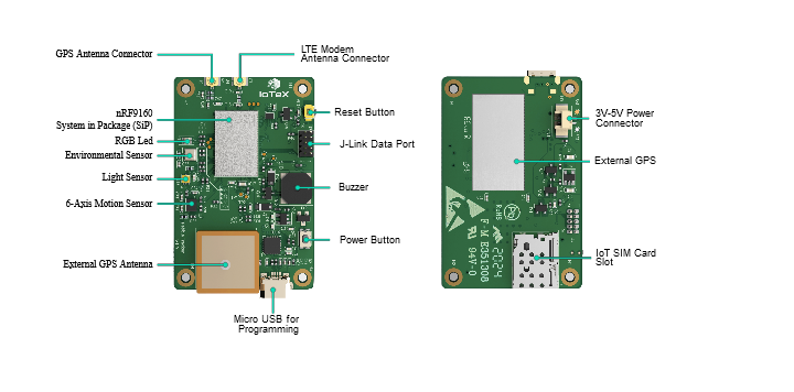
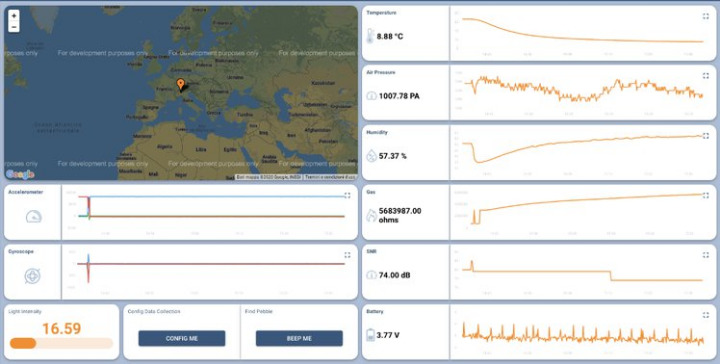
Pebble Tracker utilizes open-source firmware and functions properly with developer-friendly tools, with the addition of ThingsBoard, which is an open-source IoT platform for device management, data processing, and data visualization. Pebble Tracker consists of an expansive array of sensors — internal/external GPS, climate (temperature, humidity, air pressure, air quality), motion (acceleration, angular velocity), and light intensity. They enable trustworthy insights into an asset’s environment and movement. Pebble Tracker is verifiable and tamper-proof right from the source. It is transmittable in real-time to the IoTex blockchain of MQTT endpoint of your choice. These are possible because data is cryptographically signed. Pebble Tracker also enables you to convert real-world phenomena into verifiable digital data. By this, you can focus on building innovative asset tracking, remote monitoring, and automation solutions.

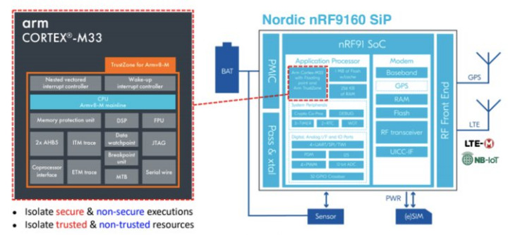
Pebble Tracker Nordic Semiconductor’s nRF9160 enables advanced processing and security accessible for low-power, cellular-IoT use cases. The nRF9160 SiP uses an ARM Cortex-M33 dedicated application processor, a multimode LTE-M/NB-IoT modem, and power management abilities to provide high performance, energy efficiency, and unparalleled security.

The nRF9160’s powerful 64 MHz Arm Cortex-M33 processor enables 1 MB of on-chip flash and 256 KB of RAM to enable advanced cellular-IoT applications possible with a single-device solution. Available also is an integrated cellular-IoT modem for LTE-M & NB-IoT which enables Pebble Tracker to operate globally and to connect with mobile network operators via SIM card, therefore eliminating the need for regional variants. The nRF9160 SiP enables power-saving features like eDRX, PSM, IPv4, and IPv6 communication, including TCP transport and TLS security.

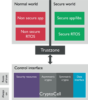
Pebble Tracker offers top-notch security with trusted execution abilities via Arm TrustZone, which helps to secure and identify the most critical processes and peripherals for your applications. Its Arm CryptoCell-310 helps improves the security of Pebble Tracker by enabling cryptographic and security resources to protect your applications from attacks. With the combined blockchain + IoT, Pebble Tracker guarantees both the authenticity of data and the verifiability of data processing without needing centralized intermediaries which can lead to errors.

Pebble Tracker enables two backend configurations: hosted and custom. The hosted backend configuration uses open-source software like hmq (MQTT broker), minIO (K8S storage), and ThingsBoard (data visualization) to enable ideation and development in a convenient plug-and-play environment. For custom configuration, you can configure Pebble to send data to any custom backend like AWS IoT Core (device management), AWS S3 (object storage), and ThingsBoard (data visualization). The configuration supports SSL/TLS client certificates, enabling maximum security and scalability.

Features & Specifications

  • MCU
    • Core:​ Arm Cortex-M33 @ 64 MHz
    • Operating supply voltage: 3 V to 5.5 V
    • Flash size: 1 MB
    • RAM size: 256 KB
    • Arm Trust zone
    • Arm Cryptocell 310
  • Modem
    • LTE-M / NB-IoT (support in bands from 700 MHz to 2.2 GHz)
    • GPS receiver (time-multiplexed with LTE modem)
    • Power saving modes
    • Secure socket (TLS/DTLS) API
  • Buzzer
    • Frequency: 2700 Hz
    • Sound pressure level (dB/min): 85 at 10 cm
  • Physical
    • Weight: ~10 g
    • Dimensions: 3.5 cm x 5.3 cm

On-board Sensors

  • TD1030 GPS
    • Position accuracy: 3m
    • Speed accuracy: 0.1 m/s
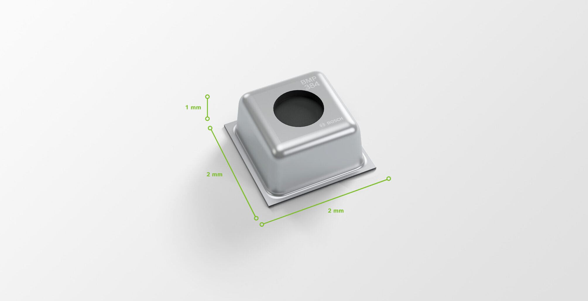
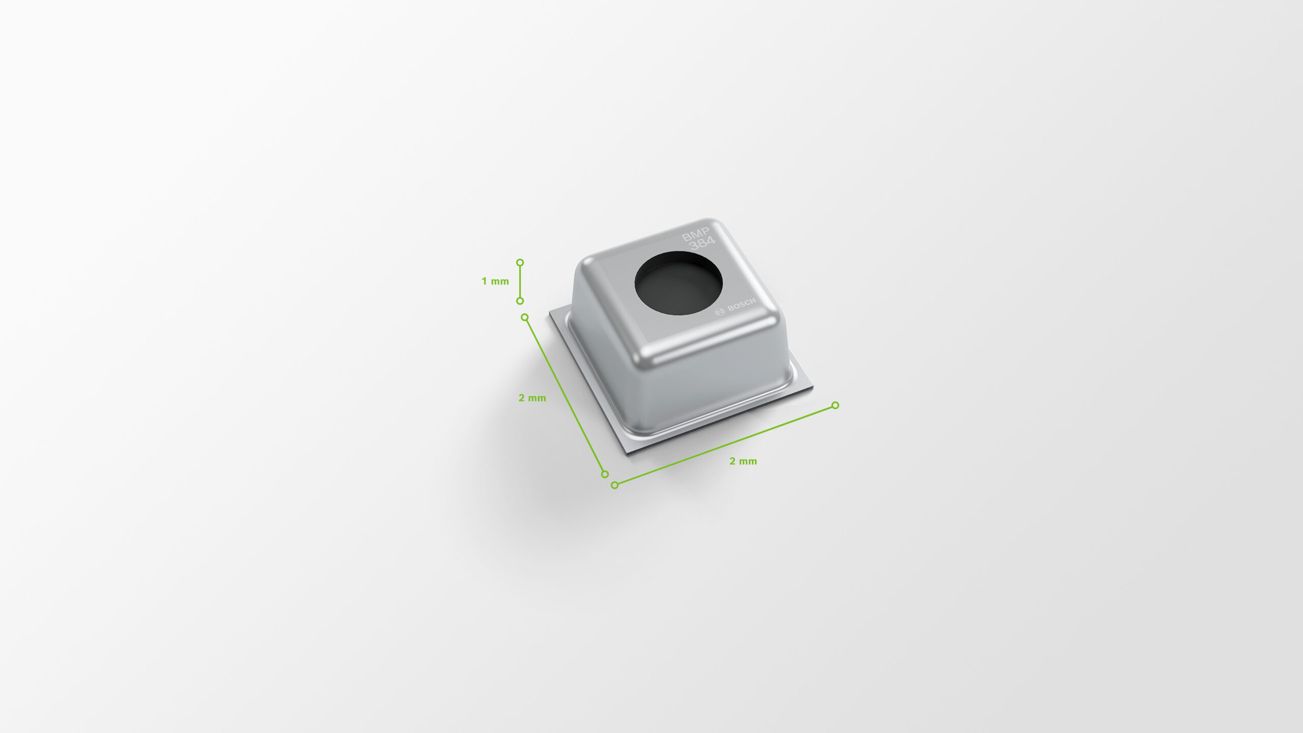
  • Bosch BME680 Environmental Sensor
    • Humidity
    • Pressure
    • Temperature
    • Air Quality (VOCs)
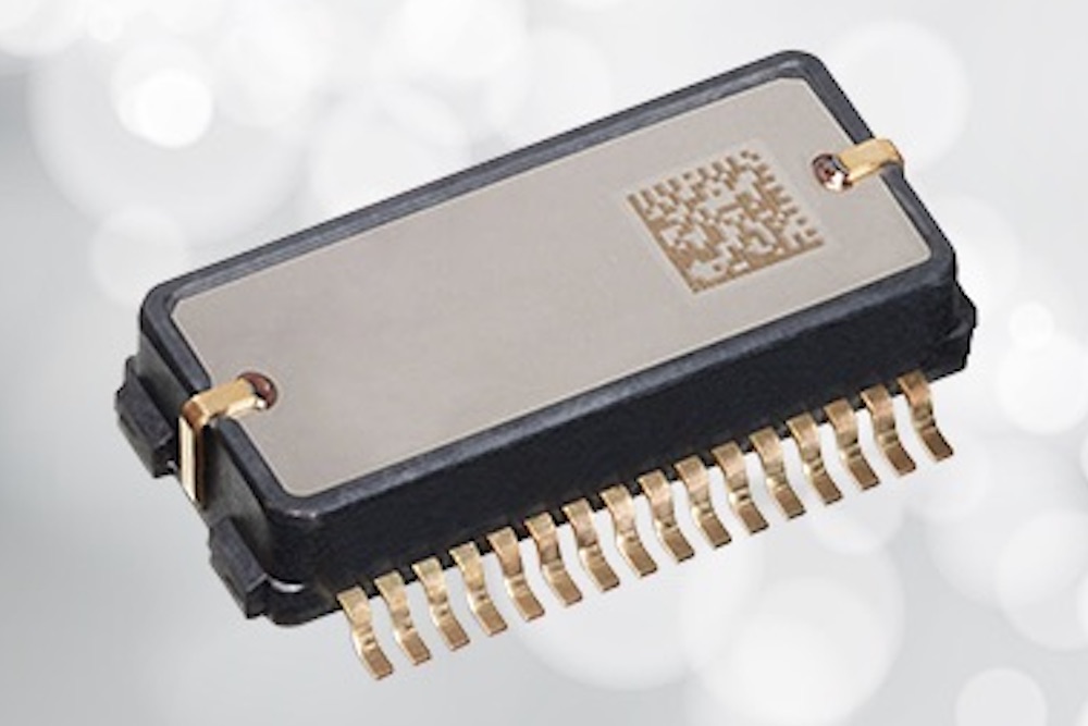
  • ICM-42605 Motion Sensor
    • 3-axis gyroscope
    • 3-axis accelerometers
  • AMS TSL2572 Ambient Light Sensor
    • 45,000,000:1 dynamic range
    • Up to 60,000 lux in sunlight
    • Very high sensitivity
    • Package UV rejection filter

Funding ends on Mar 25, 2021 at 04:59 PM PDT (11:59 PM UTC). For more information, visit the campaign page on Crowdsupply.

CP2102 USB to UART Breakout Board Features USB Type-C

CP2102 USB to UART Breakout Board

Most of the devices now come with a USB Type-C for interfacing and connectivity. Also, the USB to UART conversion is crucial for interfacing if the working device only supports a UART port. CP2102 features a USB Type-C plug for this conversion from USB to UART. We also saw a USB to UART module based on MCP220 through GPIOs, also compact USB to a UART converter using a CH330 chip with an interface speed of 2Mbps. However, there is no mention of USB Type-C for these devices.

CP2102 USB to UART is a breakout board supporting USB Type-C. The board features the CP2102 chip which belongs to Silicon Labs’ CP210x series dedicated for USB to UART Bridge through virtual COM port drivers that are needed for device functioning to facilitate host communication with CP210x based devices. These devices can also interface with a host using the direct access driver. These drivers make the USB device appear as an additional COM port available to the system.

Block Diagram of CP2102 Chip

Block Diagram of CP2102

Talking more about the CP2102 chip, it has an integrated USB transceiver with no additional need for external resistors. It comes with a 1KB programmable ROM along with the one-time programmable EPROM. The voltage regulator gives a 3.3 V output. The asynchronous serial data bus of the C02102 USB to UART supports 576 bytes receive buffer and a 640 bytes transmit buffer with hardware handshaking functionality.

The device is a fast USB 2.0 compatible that can work at data transfer rates up to 1 Mbaud. Additionally, the board supports not only the common break-out RX/TX/RTS/CTS pins, but it also breaks out almost all the other pins.  For more details regarding the break-out pins, you can see them at the back of the board.  “The signal pins are 5V tolerant – they should work with both 3.3V and 5V.” The CP2102 USB to UART board also comes with RX and TX LEDs for easing the debug issues by lighting up when data is transferring through an interface.

The motive of creating this device according to Tindie :

“We made this because certain laptops have only one USB A slot but have two USB Type-C slots. So, this board can have my USB-to-UART bridge connected and still have an empty USB A slot. This is even more useful with computers that have only USB Type-C slots.”

The CP2102 USB to UART board is available on Tindie at $5.50 USD. It comes with an assembled CP2102 breakout board with a USB Type-C Plug and a male pin header. For more information visit the product page. Images and technical specifications have also been taken from the product page.

Siglent SVA1015X 9kHz – 1.5GHz Spectrum with Vector Network Analysis

Siglent SVA1015X 9 kHz – 1.5 GHz with VNA and tracking generator included is a powerful and flexible tool for RF signal and network analysis. With a frequency range of 1.5 GHz, the analyzer delivers reliable automatic measurements and multiple modes of operation.

The Siglent SVA1015X Spectrum / Vector Network Analyzer – a powerful tool for measuring the performance of RF circuits and networks such as amplifiers, filters, attenuators, cables, and antennas. With a wide frequency range from 9kHz to 1.5GHz, the SVA1015X analyzer delivers reliable automatic measurements with its built-in tracking generator and multiple modes of operation. With the optional VNA package, this swept super-heterodyne spectrum analyzer can operate as a vector network analyzer, a frequency domain reflectometer for distance-to-fault location, and a modulation analyzer. User-friendly operation is enhanced by the choice of its 10.1” (1024×600) multi-touch screen, mouse, or keyboard input. Remote control is also possible via a web browser or a local PC (SCPI / Labview / IVI , based on USB-TMC / VXI-11 / Socket / Telnet).

Key Features:

  • Tracking Generator Standard
  • Distance To Fault (Opt.)
  • Vector Network Analyzer function (included after 9/23/2019)
  • EMI Filter and Quasi-Peak Detector Kit (Opt.)
  • Advanced Measurement Kit (Opt.)
  • 10.1 lnch Multi-Touch Screen , Mouse and Keyboard supported
  • Web Browser Remote Control on PC and Mobile Terminals and File Operation

Specifications

  • Spectrum Analysis 9 kHz – 1.5 GHz (Tracking generator covers 5 MHz to 1.5 GHz in the S.A. mode)
  • Vector Network Analysis 10 MHz – 1.5 GHz
  • Distance-to-fault (Optional)
  • Digital Modulation Analysis (Optional)
  • Touch-screen display
  • -156 dBc/Hz Displayed Average Noise Level (Typ.)
  • -99 dBc/Hz Phase Noise @ 10 kHz offset (1 GHz, Typ.)
  • 1 Hz Minimum Resolution Bandwidth (RBW)
  • Supports mouse, keyboard, and web browser-based remote control

The phase behavior of networks can be very important, especially in digital transmission systems. With its built-in preamplifier, the SVA1015X Vector Network Analyzer measures both the magnitude and phase of measured signals to quantify reflection coefficients or return loss.  By applying a test signal to a network to be tested, the reflected and transmitted signals can be compared with the original output.  Knowledge of the phase of the reflection coefficient is particularly important for matching systems like antennas for maximizing power transfer.  S-parameters are determined by measuring the magnitude and phase of the incident, reflected, and transmitted signals with the output terminated with a load that is equal to the characteristic impedance of the test system.  This technique can be used to measure the rise time of amplifiers, filters, and other networks.

Video

more information: https://www.siglent.eu

SRG-3352C: The Intelligent Solution for Edge Networks

AAEON, an industry leader in Edge Computing solutions, announces the SRG-3352C Compact Edge IoT Gateway System. The SRG-3352C brings reliable, cost-effective gateway operations with expandability and wireless communication support designed to quickly deploy edge networks in a variety of environments.

The SRG-3352C builds upon the features, durability and reliability of the SRG-3352 Edge IoT Gateway System with expanded support for more connections and wireless communications. All of this is packed into a compact form factor that makes deploying the SRG-3352C even easier, powering more flexible edge network deployments.

The SRG-3352C is powered by the Arm® Cortex-A8 800 MHz RISC processor. This innovative processor reduces the energy requirements of the system, allowing for a more efficient system to help save electricity costs. While powerful enough to connect edge networks together, the low energy usage can help cities with achieving green energy goals, and even allow the system to operate on solar power or batteries. It also eliminates the need for dedicated heatsinks, allowing the system to operate in wider temperatures, from 0°C up to 60°C without loss in performance.

The SRG-3352C is designed to provide a great value and cost-effective platform not only with initial investment, but also in long term costs. With rugged design and Arm processor, the system provides stable and reliable operation, reducing maintenance needs. To connect from edge to cloud, the SRG-3352C features built-in Wi-Fi, as well as support for 3G/4G LTE and NB-IoT to help reduce bandwidth costs.

The SRG-3352C is designed to provide a flexible platform for connecting with a wide range of edge nodes and sensors. Built in connections include two COM ports, two USB 2.0 ports, two Gigabit Ethernet ports, and an RS-232/422/485 expansion slot for Digital I/O, Isolation RS-485, CANBus, Zigbee and IO-Link wireless support. For more flexible installation, optional mounting kits including din-rail and VESA mounts make it even easier to deploy the SRG-3352C where it’s needed most. The SRG-3352C is compatible with popular cloud services including AWS, Azure, and Arm Pelion, or can be configured to work with a customer’s own cloud platform.

AAEON offers customers total end-to-end support to deploy their edge networks, from hardware like the SRG-3352C and SRG-3352 to helping build and design edge networks from the ground up. AAEON also offers customization and OEM/ODM services to help build the edge network solution customers need.

SCHA63T 6-DOF XYZ-Axis Gyroscope & XYZ-Axis Accelerometer with Digital SPI Interface

Murata has developed a new MEMS (Micro-Electro-Mechanical Systems) 6DoF (Six Degrees of Freedom) inertial sensor for autonomous Off-Highway vehicles, dynamic inclination sensing and GNSS positioning support. The sensor enables further advancement in technology and novel solutions for advanced driver / operator assistance systems, autonomous vehicles and GNSS based measurement instruments. The product delivers highest performance available on component level in key parameters like bias stability and noise. Murata calibrates orthogonality of all measurement axes. This allows our customers and system integrators to skip this costly and performance-critical process step.

Murata’s new SCHA63T sensor is the world’s first single package 6DoF component with this level of performance. Traditionally this level of inertial sensor performance has only been available on expensive high-end IMU modules. The sensor can enable centimetre-level accuracy in machine dynamics and position sensing, and can assist ensuring safe, robust and verified designs. One of the key focus areas in product development for SCHA63T has been to ensure operation during high mechanical shock and vibration. Within the same product family, there are also sensor variants qualified according to automotive AEC-Q100 standard. SHCA63T sensor includes several advanced self-diagnostic features and can achieve full compliance with ASIL-D (Automotive Safety Integrity Level).

Specifications

  • Single package 6DOF component for safety critical and AD applications
  • ISO26262 compliant for systems up to ASIL-D
  • Component level dynamic cross-axis calibration enables better than 0.3° cross-axis error over temperature
  • Allan variance down to 0.9°/h
  • Gyro RMS noise level below 0.007°/s
  • Excellent vibration robustness
  • Extensive self-diagnostics features
  • ±125°/s or ±300°/s angular rate measurement range to cover various application needs
  • ±6g acceleration measurement range
  • −40°C~+110°C operating temperature range
  • 3.0V~3.6V supply voltage
  • SOIC housing component size 19.71 ㎜ x 12.15 ㎜ x 4.5 ㎜ (l × w × h), 32 pins
  • Qualified according to AEC-Q100 standard

Murata has more than 20 years of experience of providing inertial sensors for safety critical automotive applications like electronic stability control (ESC). We have utilized this expertise in the development of this sensor family. SCHA63T sensor features extensive failsafe functions and error bits for diagnostics. These include internal reference signal monitoring, checksum techniques for verifying communication, and signal saturation/over range detection. The unique diagnostic feature of Murata’s 3-axis accelerometer is the continuously operating self-test function, which monitors the sensor during measurement. This patented self-test function verifies the proper operation of the entire signal chain from MEMS sensor element movement to signal conditioning circuitry for every measurement cycle. Even if the system using SCHA63T is not required to follow international Functional Safety standards, the provided design support documentation enables for customers a cost effective, robust & fast design process.

Product Features

  • Cross-axis calibration enables better than 0.14° orthogonality error
  • Excellent vibration robustness
  • Extensive self-diagnostics
  • Can be used in Safety Critical Applications

Applications

The SCHA63T is suitable for various applications requiring 6DOF measurement capability with high precision and reliability. The factory dynamic calibration removes the need for cost intensive and complex calibrations at module level in applications requiring accurate inertial data. Use cases are vast in various application areas like precision agriculture, construction machines and instruments, material-handling systems, robotics, professional drones, and all moving machine type of environments. Integration to GNSS will provide robust & accurate positioning with reliable, frequently updated inertial data. Murata’s partners are capable of providing algorithms, which optimize the performance for dynamic inclination sensing. Having robust inclination sensing for example in construction & Off-Highway road vehicles enables large variety of applications that support autonomous operation and improve productivity.

Please visit SCHA63T 6-DoF XYZ-axis Gyroscope and XYZ-axis Accelerometer more details.

Arduino Nano- Switching ON/OFF Appliances Using Infra-Red Remote (Two Channel)

The project presented here is a two-channel infrared remote ON/OFF switch that can be used to control home appliances, Lights, Fans, Water Pumps, Aquarium pumps, Ovens, Heaters, etc. This open-source project contains 2 x SSR (Solid State Relay), Arduino Nano, and TSOP1838 infrared receiver, keeping safety in mind, optically isolated SSR (Solid State Relay) is used to have isolation between high voltage AC circuitry and Arduino Nano. The operation of the circuit is pretty simple, TSOP1838/TSOP38238 IR Sensor receives the infrared signal from IR remote, Arduino Nano decodes the IR signal which is connected to digital pin D2 and provides latch outputs on digital pins D5, and D6 in respect to IR code received from IR remote. These two digital outputs D5, D6 drive the SSR using 2 x BC847 BJT transistors. CPC1998J optically isolated solid-state relays from IXYS Integrated Circuits drive the AC loads. We have tested this board with 500W/230V AC lamps, however, the load capacity of SSR is 20A. A snubber circuit is provided across the SSR-Traic which helps driving inductive loads. Heat-sink on SSR is not required for loads up to 5A, but for higher load, it is advisable to mount a heatsink on SSR.

Arduino Nano- Switching ON/OFF Appliances Using Infra-Red Remote (Two Channel) – [Link]

TOP PCB Companies