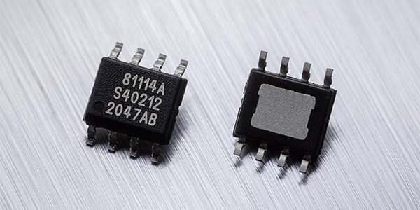
The new member – the MLX81114 – supports the further growth of RGB LED-based automotive ambient lighting, also known as LIN RGB, which is already well established within nearly every OEM worldwide. The MLX81114 is a variant of the MLX81113 featuring a memory access protection which enables anti-theft applications, and is exclusively available in SOIC packaging.
Other features include on-chip memory, high output current and EMC robustness next to the ISO 26262 functional-safety compliance to support its use in ASIL-A classified systems.
With automotive lighting as one of the key features for personalization and differentiation within the driver’s cabin, Melexis responds to this trend with its offering of LIN-compatible RGB(W) drivers to enable sophisticated yet cost-effective ambient lighting for vehicles from entry-level to mid-range and luxury models.
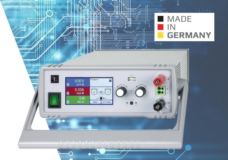
The PS9000 family of laboratory power supplies from Elektro-Automatik offers a reliable and user-friendly solution for every electronics engineer. Opt for high quality, safety and compact size.
General description
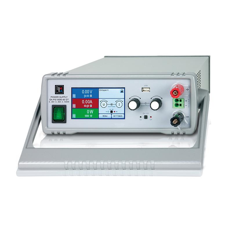
The microprocessor-controlled laboratory power supplies of EA-PSI 9000 DT series offer a user-friendly, interactive handling concept, along with an extensive set of standard features, which can facilitate their operation. Configuration of output parameters, supervision features and other settings is smart and comfortable. The implemented supervision features for all output parameters can reduce test equipment and make it almost unnecessary to install external supervision hardware and surface.
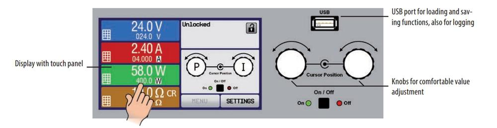
The clear control panel with two knobs, one pushbutton, two LEDs, and the touch panel with a colour TFT display for all important values and status enables the user to handle the device with a few fingers touches easily.
The device offers a set of interfaces (analogue and digital) on its rear panel for integration into semi-automatic and remotely controlled test and automation systems.
AC power supply input
The device uses an active Power Factor Correction (PFC), enabling worldwide usage of a mains input from 90VAC up to 264VAC. Models with 1,5kWwill derate their output power to 1kW below input voltages 150VAC.
Auto-ranging power stage
All models are equipped with a flexible auto-ranging output stage which provides a higher output voltage at lower output current, or a higher output current at lower output voltage, always limited with a maximum output power curve.
Highlights:
Autoranging
Color Touchscreen
3-paths onboard Interface
Technical Specifications:
Nominal powers 320W, 640W, 1000W, 1500W
Nominal voltages 40V, 80V, 200V, 750V
Currents 0-60A
Available Features:
Color Touchscreen
Wide input supply voltage range 90…264V with active PFC
High efficiency, up to 92%
Interfaces: USB standard, Ethernet & Analog optional
LabVIew-Vis software
40V-Models according to SELV under EN 60950
DC output
DC output voltages between 0…40V and 0…750V, output current between 0…4A and 0…60A and output power ratings between 320…1500W are available. Thus, current, voltage and power could be adjusted continuously between 0…100%, no matter if manually or remotely (analogue or digital). The output terminals are located at the front panel of the device.
The PSI 9000 DT power supply features an additional built-in output filter to achieve much lower ripple, i.e. low noise on the DC output voltage.
Desktop power supplies from Elektro-Automatik are available to order. We will check the price and delivery dates directly with the supplier.
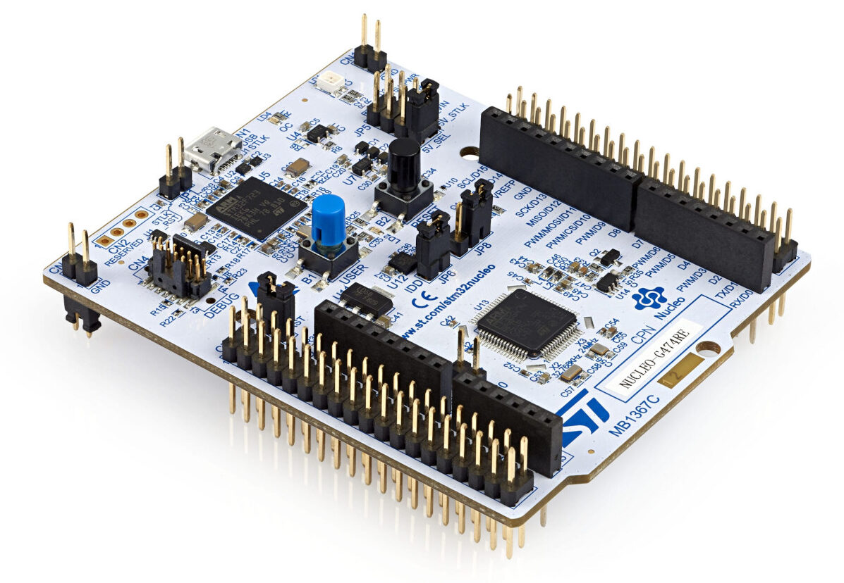
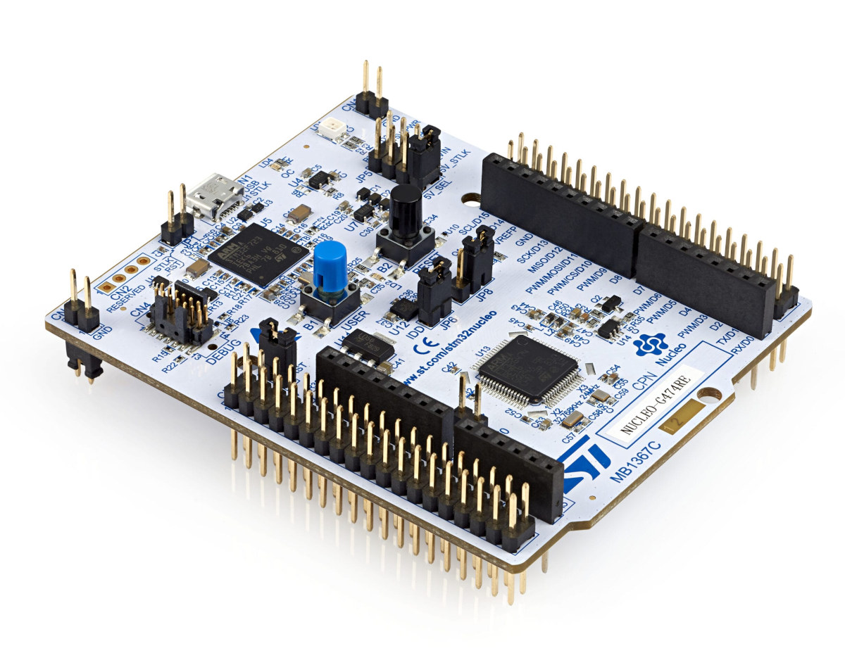
The STM32 Nucleo-64 board provides an affordable and flexible way for users to try out new concepts and build prototypes by choosing from the various combinations of performance and power consumption features, provided by the STM32 microcontroller. For the compatible boards, the external SMPS significantly reduces power consumption in Run mode.
The ARDUINO® Uno V3 connectivity support and the ST morpho headers allow the easy expansion of the functionality of the STM32 Nucleo open development platform with a wide choice of specialized shields.
The STM32 Nucleo-64 board does not require any separate probe as it integrates the ST-LINK debugger/programmer.
The STM32 Nucleo-64 board comes with the STM32 comprehensive free software libraries and examples available with the STM32Cube MCU Package.
Key Features
Common features
STM32 microcontroller in LQFP64 package
1 user LED shared with ARDUINO®
1 user and 1 reset push-buttons
32.768 kHz crystal oscillator
Board connectors:ARDUINO® Uno V3 expansion connectorST morpho extension pin headers for full access to all STM32 I/Os
Flexible power-supply options: ST-LINK, USB VBUS, or external sources
On-board ST-LINK debugger/programmer with USB re-enumeration capability: mass storage, Virtual COM port and debug port
Comprehensive free software libraries and examples available with the STM32Cube MCU Package
Support of a wide choice of Integrated Development Environments (IDEs) including IAR Embedded Workbench®, MDK-ARM, and STM32CubeIDE
Board-specific features
External SMPS to generate Vcore logic supply
24 MHz HSE
Board connectors:External SMPS experimentation dedicated connectorMicro-AB or Mini-AB USB connector for the ST-LINKMIPI® debug connector
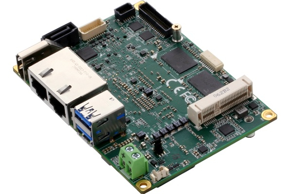
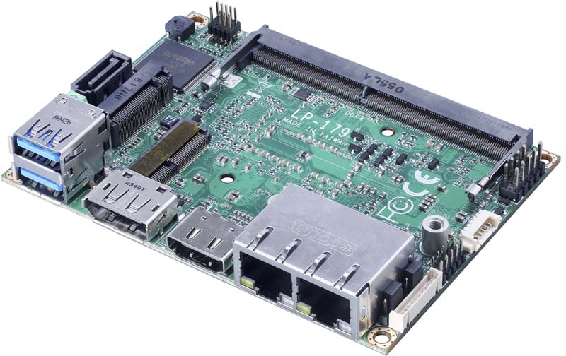
Taiwan Commate Computer Inc .(COMMELL), the worldwide leader of Industrial Single Board Computers, unveiled LP-179 & LV-6712 Mini-ITX based on Intel® 11th Gen. FCBGA1449 “Tiger Lake UP3”.
The 11th Gen Intel® Core™ processor is claimed to deliver better performance up to a 23% gain in single-thread performance, and up to a 19% gain in multi-thread performance vs. 8th Gen Intel® Core™ processors, up to 96 graphics execution units, deliver high-performance CPU/GPU compute with integrated AI acceleration, plus capabilities for applications that demand high-speed processing, and low-latency deterministic computing.
The COMMELL LP-179 & LV-6712 platform provides excellent CPU, graphics, media performance, flexibility, and enhanced security, is ideally suited to applications requiring multi-tasking capabilities, such as gaming, surveillance, medical, defense, transportation and industrial automation application.
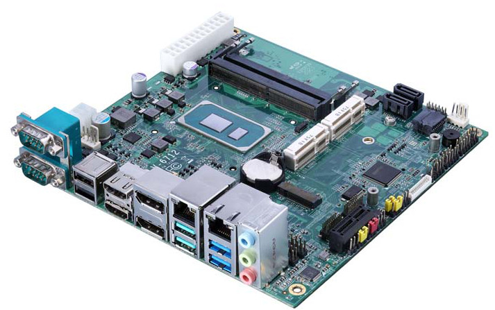
LV-6712
The LP-179 & LV-6712 Mini-ITX is designed for the 11th generation Intel®Core™ i7-1185G7E and Celeron® 6305E, The Core™ i7 part has a 1.8GHz base clock with 12MB cache and a 4.4GHz max turbo frequency, The Core™ Celeron part has a 1.8GHz base clock frequency with 4MB cache, both CPUs offer long-life availability.
The LP-179 features one DDR4-3200 SO-DIMM slot for up to 32GB of memory. LV-6712 features two DDR4-3200 SO-DIMM slot for up to 64GB of memory.
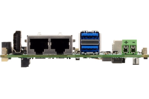
LP-179 Displays one HDMI, one DP ports onboard, optional LVDS interface by ADP-3460 module. Lp-179 offers 2 x USB2.0, 2 x USB3.2 Gen2 and 1 x SATAIII, equipped with one Gigabit Ethernet,
and one 2.5Gb Ethernet,(1 x Intel® I219-LM Gigabit PHY LAN and 1 x Intel® I225-LM 2.5 Gigabit LAN), and comes with internal 2 x RS232,1 x HD Audio, 1 x M.2 Key M 2280 for support PCIe Gen4 device such as NVMe, 1 x M.2 Key E 2230 for Wi-Fi & BT module, Standard 12V DC input.
LV-6712 Displays LVDS, two HDMI and two DP ports onboard, up to four displays can be controlled simultaneously.
LV-6712 offers the features as 4 x USB2.0, 4 x USB3.2 Gen2 and 2 x SATAIII, equipped with one Gigabit Ethernet, and one 2.5Gb Ethernet,(1 x Intel® I219-LM Gigabit PHY LAN and 1 x Intel® I225-LM 2.5 Gigabit LAN), 2 x RS232/422/485 onboard and comes with internal PS/2 port, 4 x RS232,1 x 8bits GPIO, 1 x HD Audio, 1 x SMBus, 1 x M.2 Key M 2280 for support PCIe Gen4 device such as NVMe, 2 x MiniPCIe(slot 2 support mSATA), 1 x PCIe X1 slot, Standard 24-Pin ATX or 4-Pin 9~35V DC input.
As we have seen in previous tutorials, circuits can be categorized by the number of states that they can be stable. For example, in the op-amp multivibrator tutorial there were astable, monostable, and bistable versions of the circuit. This tutorial will focus on the monostable form of the circuit, specifically the implementation for an op-amp.
A monostable circuit is simply a type of circuit that has a single state that is stable. In most cases, this takes the form of a circuit that takes a trigger pulse of any length and outputs a pulse of a set length. The output pulse length is purely decided by the components that make up the circuit, and not the input pulse. So for example, if we have a monostable circuit with a time constant of 1ms, it would not matter if a 1us pulse or a 0.1ms pulse triggers it, the output pulse would always be 1ms long. Many different components could be used to make such a circuit, such as transistors, 555 timers, and digital logic gates, but in this tutorial, we will focus on the monostable op-amp circuit.
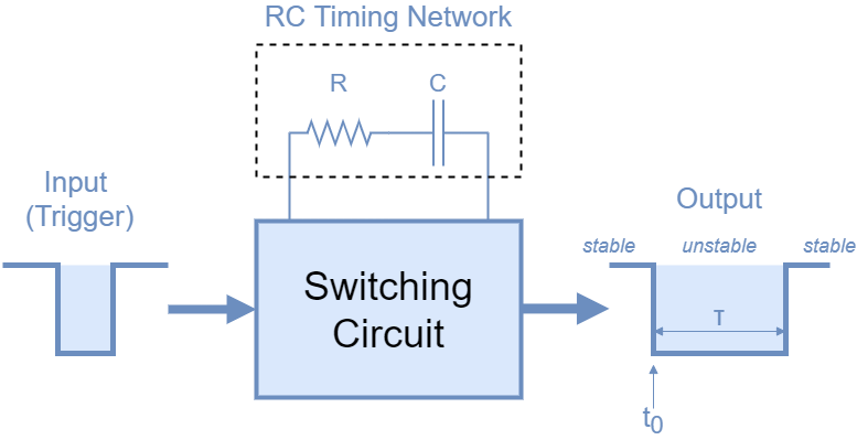
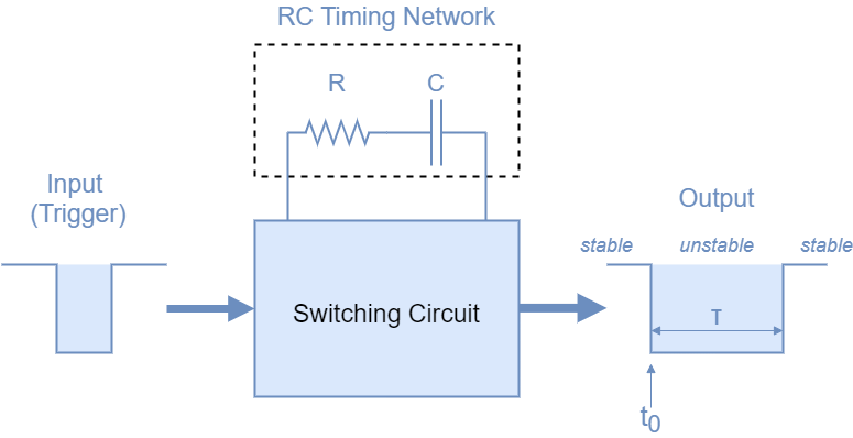
fig 1: Monostable circuit block diagram
As you can see in figure 1, a monostable multivibrator is based around a resistor (R) and capacitor (C) circuit. These RC circuits are common in electronics and have a designated Greek letter Tau – τ to show this is a time constant. Changing the resistor and capacitor values will affect the time constant of the circuit.
Previous Circuit Recap
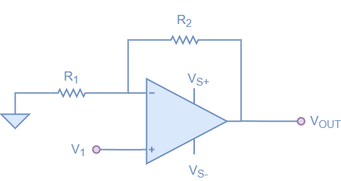
fig 2: Inverting Op amp
Similar to the multivibrator tutorial, the monostable op-amp circuit is based around a Schmitt comparator. To revise how a Schmitt comparator functions, it is set up similarly to an inverting op-amp, but instead of the resistor divider feeding back into the negative input, it is fed back into the positive. This provides a form of hysteresis, where the threshold changes depending on which state it is in.
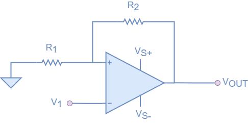
fig 3: Schmitt comparator
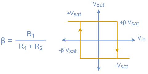
The op-amp Schmitt comparator can be seen as a bistable circuit, as it has two stable states, with Vout only being stable at Vs+ or Vs-. The hysteresis is defined by the resistor network but has the opposite effect to the inverting op-amp. Instead of the op-amp output forcing the op-amp inputs together, in this configuration, it continues to amplify until it hits the supply rail. So when Vout is saturated towards Vs+ supply rail, the voltage at the positive input is positive with respect to ground. Similarly, when Vout is saturated to Vs- supply rail, the voltage at the positive input is negative with respect to ground. As with all resistor feedback networks, it uses the feedback equation shown below, and this feedback value has an impact on how the hysteresis functions, and defines the point that the input needs to reach for the comparator to switch.
fig 4: equation used to calculate feedback, and the graph that the Schmitt comparator produces.
Note that with the above circuit, it is a bad idea to have very low values for hysteresis, as it will likely cause instability and unexpected switching. A similar circuit is used all of the time for inputs to microcontrollers, logic, and CPU’s. If you want to experiment with the circuit at home, you can always use a potentiometer in place of the two resistors, so you can change the feedback point, but it is a good idea to put it in series with a fixed resistor to stop the switching characteristic.
Basic Monostable Op-amp Circuit
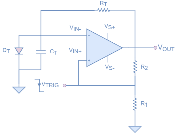
fig 5: basic monostable op-amp circuit
Figure 5 shows the basic monostable op-amp circuit, which we will use to describe the functionality and how it works. The circuit is controlled by a single input Vtrigand has a single output Vout and just a single active component, the op-amp.
For the setup above, with the diode in that direction, the stable state for the circuit is for Vout to be positive (Vsat+). Even with no input on Vtrig, Vout will likely swing high (after some instability). At that point, the feedback of R1 and R2, will create a potential of Vsat+*β where β is the feedback fraction described above. With Vout being forced to Vsat+, Vin- experiences a positive voltage, which is being clamped to 0.7V due to the diode being in the conducting direction (0.7V is the forward voltage of a standard diode). With Vin- being 0.7V, it is much lower than Vin+, which is why Vout is forced high. At this point, the capacitor in parallel with the diode is charging to 0.7V potential. At this point the circuit is stable.
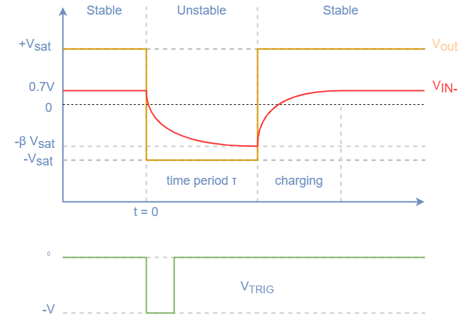
If at this point a negative voltage pulse is applied to Vtrig, Vin– at 0.7V is higher than the negative pulse at Vin+. As we saw with the Schmitt comparator, this switches the state of the circuit. This different state forces Vout negative to Vsat-. If we assume the pulse is very short (we can deal with this in the next session) the voltage at Vin+ is Vsat-*β. At the same time, Ct now experiences a negative voltage (via Rt) which is not being clamped by the diode. This voltage causes the capacitor to start charging via Rt down to Vsat-. The capacitor Ct will continue to charge towards Vsat- until it reaches the same potential as Vin+, which is being set by the feedback resistors, meaning Vin+ is Vsat-*β. When the capacitor reaches this value, the Schmitt comparator switches the state back to Vsat+, its original state. The process then reverts to its original state, with the capacitor charging back to 0.7V.
fig 6: The waveforms generated by different lines in the various states of the monostable op-amp
Some things should be noted about the above circuit that should be considered when designing it into your own circuitry. The capacitor Ct needs to recharge after the circuit returns to its stable state. This charging is through the same feedback resistor that it discharges through Rt. The other consideration is that the input pulse in Vtrig is assumed to be shorter than the time period of the charging part of the circuit. If this was not the case, and the pulse was longer, the circuit would remain unstable until the pulse returned positive.
Calculations
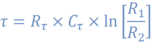
Fig 7: Calculation for monostable op-amp timing period
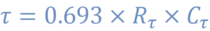
Figure 7 shows the equation used to calculate the time constant in the monostable op-amp circuit shown above, but to make it simpler, most engineers will use the same value for R1 and R2. This also makes the calculation simpler, producing the equation shown in figure 8. Now using this equation, the RC constant is directly proportional to the time constant, which makes the design simpler and easier to modify.
Fig 8: Simplified equation to calculate the timing constant
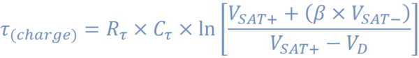
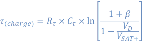
We can also calculate the time that it takes for the capacitor to charge from the switching point (Vsat-*β) and Vd (~0.7V). In this time where the circuit is recharging, it is important that a signal coming in is not expecting to make another pulse. So when programming into your circuit the minimum wait time, we can use the more complex equation shown in figure 9. In most cases, it is safer to just add a safe time, and not go through using the equation, but if your application requires fast pulses, you may need to optimize this time.
fig 9: Recharge period of the capacitor in the monostable op-amp
RC Differentiator Circuit
As discussed and shown above, this circuit will often need a particularly short pulse to trigger the mechanism, and depending on what is being used to trigger it, this pulse could have to be quite long (if you are using a microcontroller with a slow clock for instance), this is where the RC differentiator comes in. The basic form of this circuit utilizes the same RC phenomenon that the monostable op-amp uses to create the trigger, but this time in a slightly different format. Laid out similarly to a high pass filter, with a diode to only allow current in one direction.
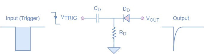
fig 10: Basic RC differentiator circuit
As we expect, the circuit triggers when the input goes from 0 to -Vs. At this point, the capacitor Cd begins to charge in the classic exponential capacitor charging curve. As the voltage across the capacitor is initially 0V, the output of the circuit immediately jumps to -Vs, which is seen as a spike on the output. As the capacitor charges, the output slowly returns back towards 0V in the classic capacitor curve. The diode is in a configuration where only a negative spike can pass through the circuit. If a positive trigger was applied, a spike would be produced by the capacitor, but blocked from the output by the diode.
There are some basic design rules that need to be considered when designing an RC differentiator like this. The first is to assume that the negative spike produced by the circuit will be less than or equal to the trigger voltage, which could impact a circuit that may need a larger spike. One other consideration is how to size the RC circuit. A well-followed rule, that should produce good quality spikes is to make sure the time constantτ is at least 10 times smaller than the expected input pulse width. If we use the calculation 5*Rd*Cd as the equation, if we had a pulse of 100ms, the outcome of 5RC should be less than 20ms (but closer to 10ms is better).
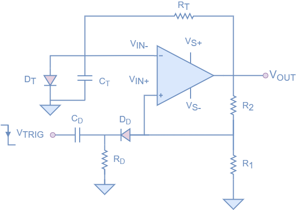
If we add the RC differentiator to the monostable op-amp circuit, we get the circuit shown in figure 11.
fig 11: The final Monostable op-amp circuit
Conclusion
As we have seen in this article, an op-amp can be usefully used as a monostable circuit, and it can be modified to make longer or shorter pulses based on the resistors and capacitors chosen. This is a useful circuit, and monostable circuits can be very useful in modern electronics. Equally, almost any op-amp can be used, making the circuit universal. When designing, keep in mind that this exact behavior can be found by using other common components, such as 555 timers. Depending on what you need to achieve in your circuit will define which part you use.
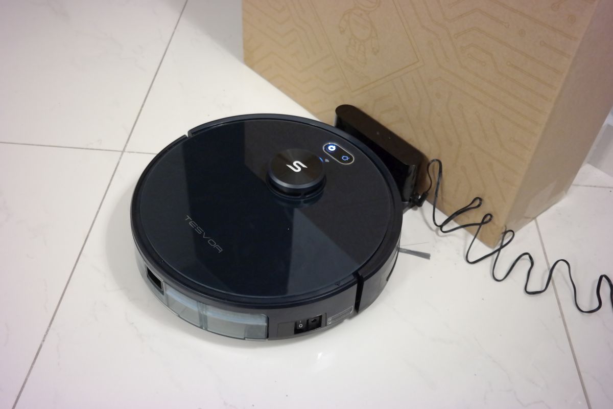
Tesvor S6 is a Laser Navigation 2700Pa Auto-Charging Robot Vacuum Cleaner which is Compatible with Alexa/App and it is Ideal for Pet Hair & Dust, Carpets & Hard Floors.
Tesvor S6 robot vacuum cleaner is a laser navigation 2700Pa auto-charging robot vacuum cleaner compatible with Alexa/App, and it is ideal for pet hair & dust, and it can vacuum multiple surfaces and debris types. The robot vacuum’s artificial intelligence laser LIDAR navigation technology enables the vacuum to pinpoint obstacles accurately but seems that some training is needed to avoid stalls. Unboxing the vacuum, you find a docking station, battery, clean roller brush,side brushes, and a dust box.
What’s in the box?
Tesvor S6 robot vacuum
Charging dock & power cord
Remote
Cleaning tool
Replacement left & right brushes
Replacement high-efficiency filter
User guide
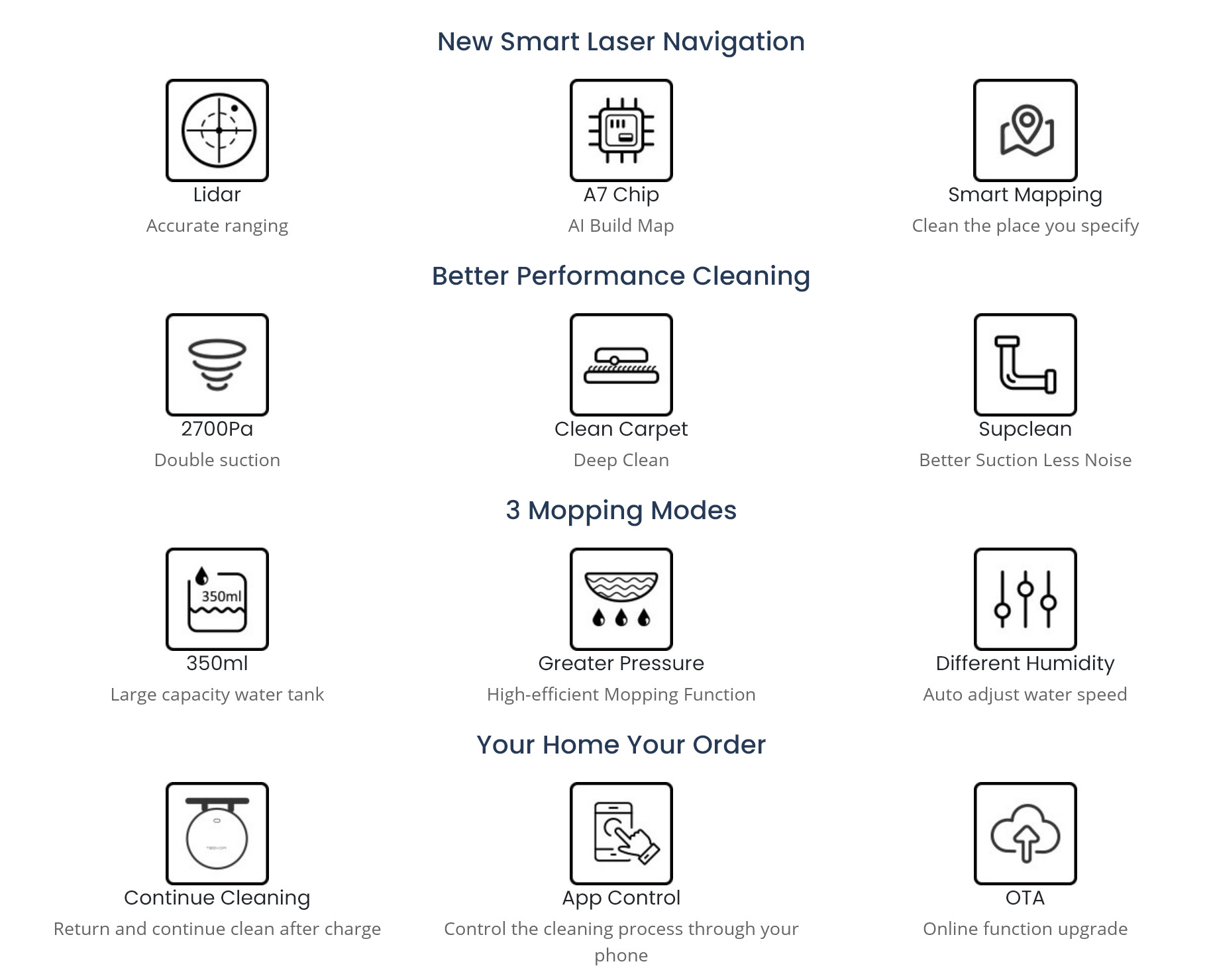
The AI technology enables the vacuum to record all areas where it needs to vacuum, making a room map to clean it properly. The laser navigation technology that the robot vacuum features enables it to navigate through all sorts of spaces that are filled with objects and obstacles. The use of its laser navigation systems can map out these spaces and what is within the spaces. Doing so allows the robot vacuum to develop plans for each space, ensuring that every space within your home is vacuumed thoroughly and efficiently.
The Tesvor S6 has many sensors to help it navigate through the house. It has a front bumper sensor as well as front scanning sensors which allows it to gently bump into things as it navigates around the house. The disk on top of the vacuum is a rotating scanning laser that maps the whole house as it runs and shows a projection on the mobile app. It is able to detect small protrusions and even where a door is open or closed. The map it creates is updated every time the vacuum is run which makes the map more and more detailed and accurate the longer the robot is running. This means that you need to give the robot some time to adapt to your environment and get to know it.
On the underside of the vacuum, there are two side sensors, which monitor the surface the vacuum is operating on. These sensors also detect if the robot is near a staircase and in danger to drop off. The charging points, match up to the charging dock while charging. If the robot doesn’t sense that both points are in contact with the dock, it will retry to dock correctly. In real-life experience, we found that sometimes it gets hard to dock itself on the charging station and needs several re-tries, even if it’s very close to the base. So you will need to allow some time to find its way to charge.
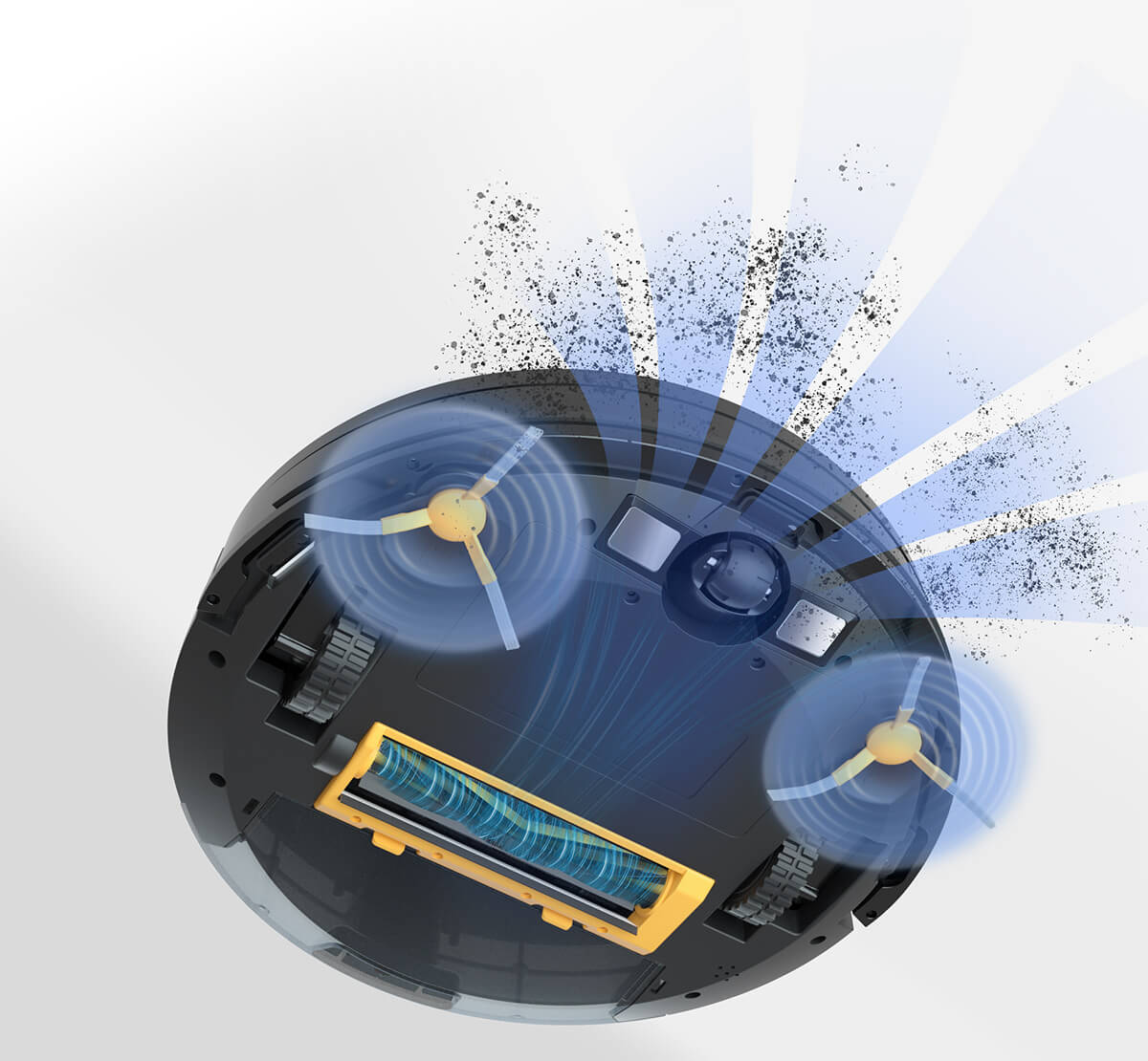
Another feature of the vacuum is that it has the option to switch between normal power mode, max power mode, and boost the power on both an automatic and manual basis. The vacuum detects the nature of the floor surface it needs to clean. For normal mode, a normal cleaning can be completed in about 1 to 1.5 hours for an average house. You don’t have to move the vacuum after it is done with cleaning, the vacuum automatically returns to the charging base after cleaning is completed, or the battery power is insufficient. Its powerful turbofan combined with the dust collection effect of bilateral brushes, and efficient air duct design to achieve a strong single cleaning ability. No need to clean again manually.
The Tesvor S6 vacuum comes with a large-capacity dust bin, remote control, and option to be paired with a mopping stick. There is also a precision micro-control water pump that cooperates with the high-performance chip to precisely control the water output. 3 levels of water outlet speed adjustment to adapt to different home environments. However, you have to purchase the water tank separately.
Since it is a WiFi-connected vacuum cleaner, it can work with Alexa and Google Home and you can also connect it to your smartphone. This enables you to access the robot vacuum just about anywhere, and give it direction through those devices or you can use the free app from the vacuum cleaner company. One feature you get access to if you choose to use a smart home device to access and control the robot vacuum is the various voice control features. The voice control features include turning on the vacuum with your voice and activating a vacuum mode with your voice. This feature enables an extremely convenient vacuuming experience.
The reason for the Tesvor S6’s efficiency is the 2700Pa of suction power it offers. This enables it thoroughly vacuum and clean just about any surface. Vacuuming with the Tesvor S6 on hard floors is very easy, and likewise vacuuming on soft floors, such as rugs and carpets. So, regardless of the nature of your floor, you can use the robot vacuum to clean your floors thoroughly. If you are using a smartphone, or the smart home app that the robot vacuum offers, there is a feature called the “zone cleaning” feature which you can access. The zone cleaning feature enables you to choose selected spaces that you want the robot vacuum to clean. This feature enables you to direct the robot vacuum to clean only the area you need to be cleaned. This helps tailor the cleaning to your need and expectations.
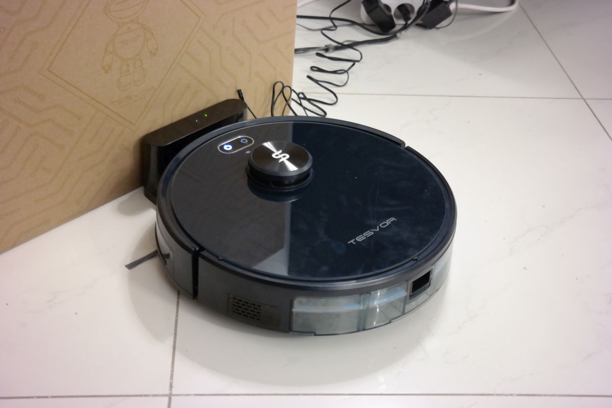
Tesvor S6 returning home
Mobile App
The first-time configuration of the Android app took us ~10 min to complete, as you will need to register an account and add the vacuum as a new device on the app by scanning a QR code and connecting to the Wifi of your home. Once this is done the app shows the status of the vacuum and the charge level on the screen. On our first try to command the vacuum to start cleaning there were some connection issues that we couldn’t overcome. So we waited to see if this resolves. It seems it often loses the wifi connection with the router even if we used a WiFi repeater in the center of the house. In order to get it to connect, you have to turn it off while it’s on the charging dock, then pull it off of it so the vacuum no longer charging. After about five minutes, push it back onto the dock while still off then turn it on once the robot is charging again. This could be an issue, especially if you are remotely controlling the vacuum through the internet.
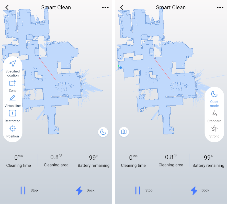
In order to assist the robot in cleaning the app provides options to send the robot to a specified location, set a zone to clean, create a virtual line, indicate restricted zones, and locate where the robot position is. All these indicate you will need some time to spend to get familiarize with the device even if it considered a smart one. Also, we didn’t find a way to change the voice language of the vacuum to English as it seems it’s in German by default.
Live Mapping
Pros
Powerful suction for a robot vacuum which is also adjustable (three running levels, quiet, standard, and strong)
Intelligently maps your house through the mobile app
Smart features + Wifi connectivity
Live updating laser mapping
Washable filter
Cons
Pricey
Loss of Wifi Connection
Configuration issues
~1.5hr battery life in normal mode
The Tesvor S6 robot vacuum is efficient, durable, and will do the hard work for you, but you will first need to configure it and allow it to know your space .
The robot vacuum is available for $320 on Tesvor’s product page or $299.99 on Amazon. Promo code: US$20 OFF with Code: TCS610
We saw the launch of Arduino Porenta H7 last year, it features programming in high-level languages and AI and at the same time, it performs low-latency operations on its customizable hardware. However, the board supported an inbuilt module dedicated to professional and industrial applications, apart from its popularity amongst the hobbyists.
Arduino also launched a Vision Shield add-on for enabling edge computer vision on Arduino Porenta H7 in late 2020. The Vision Shield add-on was a significant enhancement, as it allowed the computer vision and “always-on voice capabilities” supporting the additional hardware needed for on-device computing.
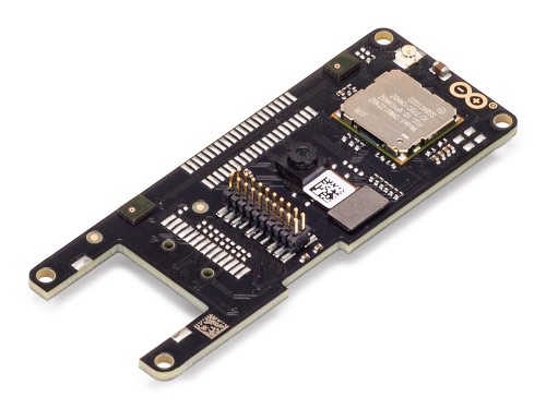
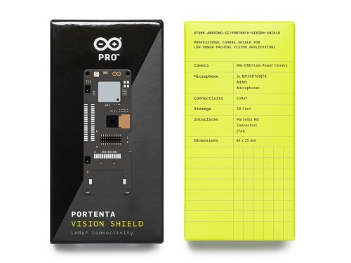
Portenta Vision Shield LoRa is another variant in the edge AI vision board that features LoRa wireless connectivity. It comes with a Himax HM-01B0 low-power camera sensor and an all-directional pair of microphones. Additionally, it has a new LoRa radio module capable of enabling long-range communication links.
Arduino says
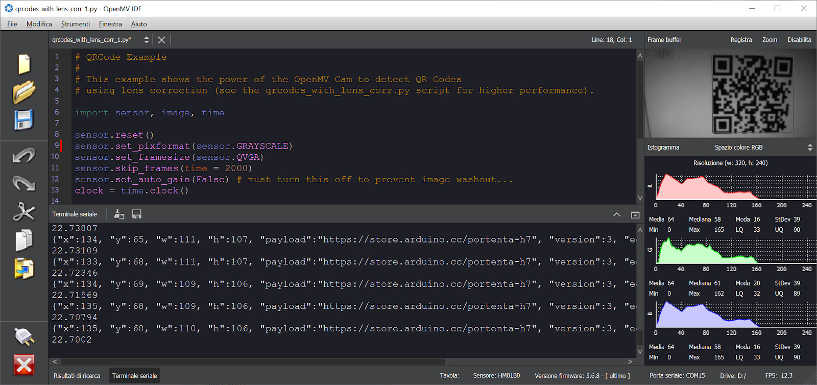
“Both the video and audio data can be stored on an SD card and transmitted through the LoRa module to the Arduino IoT Cloud or your own infrastructure. Also, Companies across the whole world are already building their commercial products based on this simple-yet-powerful approach to detect, filter, and classify images, QR codes, and others. “
Technical Specifications of Arduino Portenta Vision Shield LoRa
Himax HM-01B0 camera module for computer vision applications
Resolution of 320 x 320 active pixel resolution with support for QVGA
Image sensor features high sensitivity 3.6μ BrightSense pixel technology
2x MP34DT05 microphones capable of detecting acoustic waves
868/915MHz ABZ-093 LoRa Module with ARM Cortex-M0+ for connectivity
Length: 66 mm and Width: 25 mm
Weight 8 grams
Portenta Vision Shield LoRa features a camera sensor that works on the core to perform image recognition algorithms. The device uses the OpenMV framework for the Arduino editor. It supports a long-range 868/915MHz LoRa wireless connectivity for Portenta H7 for interfacing IoT with low power consumption. It also comes with a pair of on-board microphones for directional sound detection. This enables real-time sound capturing and analysis. Also, the JTAG connector functions low-level debugging of the device using an external programmer.
Talking more about the OpenMV framework, it provides a free license to the OpenMV IDE. The environment is simple to integrate computer vision functionalities using the MicroPython as a programming medium. One can download the OpenMV for Arduino Editor from the professional tutorials site and browse through the examples that the company has created on the platform itself.
Hackster’s post has brought to our attention that the LoRa connectivity allows the
“new Portenta Vision Shield to connect with The Things Network, a community-driven worldwide network of LoRaWAN gateways designed to offer ultra-low-cost high-performance connectivity for a range of IoT applications.”
The Arduino Portenta Vision Shield LoRa is available at a price of $63 from the Arduino Store. For more information visit the official product page. Images and technical specifications have also been taken from the product page.
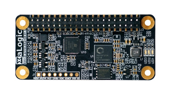
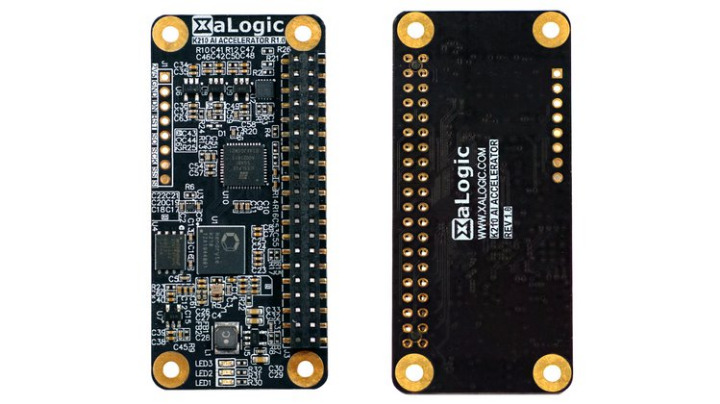
XaLogic had launched a campaign on Crowdsupply for a Kendryte K210 based HAT. The K210 AI Accelerator is a compact Raspberry Pi HAT that utilizes the Kendryte K210 AI processor to enable 0.5 TOPs (Tera Operations Per Second) of processing power. Kendryte K210 is a dual-core RISC-V AI processor that was launched in 2018, and you can find it in several smart audio and computer vision solutions. The HAT also supplies a Trust-M security chip. The 65 x 30mm HAT is designed to be compatible with any 40-pin Raspberry Pi equipped with an RPi camera add-on. The HAT enables you to add AI features to your RPi based camera even if you don’t know how to train your model. The plugin module, as well as the pre-trained models, will make your camera AI-enabled in minutes with a few Python API calls. Its Kendryte K210 SoC provides 0.5-TOPS NPU performance and can run at as low as 0.3W. This is in contrast to Coral Edge TPU which clocks at 2W, and 1.5W for Intel’s Myriad X powered Neural Compute Stick 2, with both of them running at about 4 TOPS.
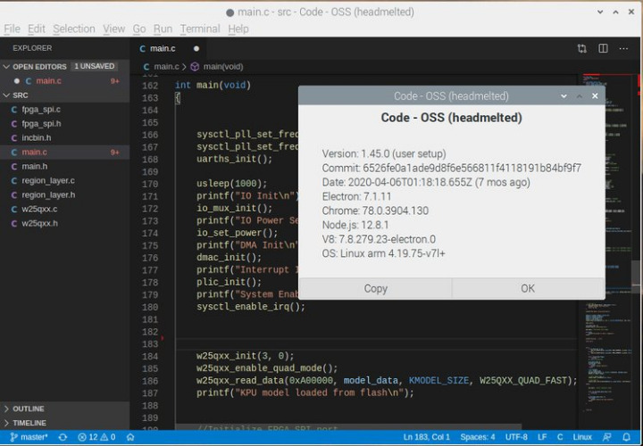
K210 firmware
XaLogic K210 AI Accelerator functions best with Raspberry Pi Zero and camera and enables you to make use of pre-trained models for evaluation such as object detection, face detection, age, and gender estimation, simple voice commands, and vibration abnormally detection. You can also train your own model using a more powerful host machine. You can make use of an NVIDIA GPU, with TensorFlow. You can make use of TFLite, Caffe, and even ONNX format through the aid of conversion tools. You can make use of Visual Studio Code, which is recommended by XaLogic to modify K210 C code directly on Raspberry Pi if need be. With the aid of the Visual Studio Code for Raspberry Pi and the pivotal toolchain for the K210, you can develop all the K210 firmware on the Pi itself. The K210 AI Accelerator features an Infineon Trust-M onboard which enables you to establish a secure connection to AWS through MQTT without exposing the private key. This feature is important for your privacy when you are deploying your IoT devices in the field.
The K210 is open source, and the company says:
“Schematics, C code in the K210, and all code running on the Raspberry Pi will be open-sourced. Pre-trained models are provided in binary form. Also, sample Caffe and Tensorflow projects are available to help you create your own custom neural network.”
The company plans to manufacture the K210 AI Accelerator in China. They have also carried out a trial run of a small batch to iron out any manufacturing issues. Regarding Logistics, Crowd Supply will fulfill your pledges via their logistics partner, Mouser Electronics. The K210 AI Accelerator HAT is over halfway toward its $3,000 goal. The module will ship in late May. Available also is a 40-pin extender for $3 which enables connection with the Raspberry Pi 3B+ or 4B to avoid an obstruction conflict with the PoE header.
K210 AI Accelerator board specifications:
SoC – Kendryte K210 dual-core 64-bit RISC-V processor @ 400 MHz with 8MB on-chip RAM, various low-power AI accelerators delivering up to 0.5 TOPS,
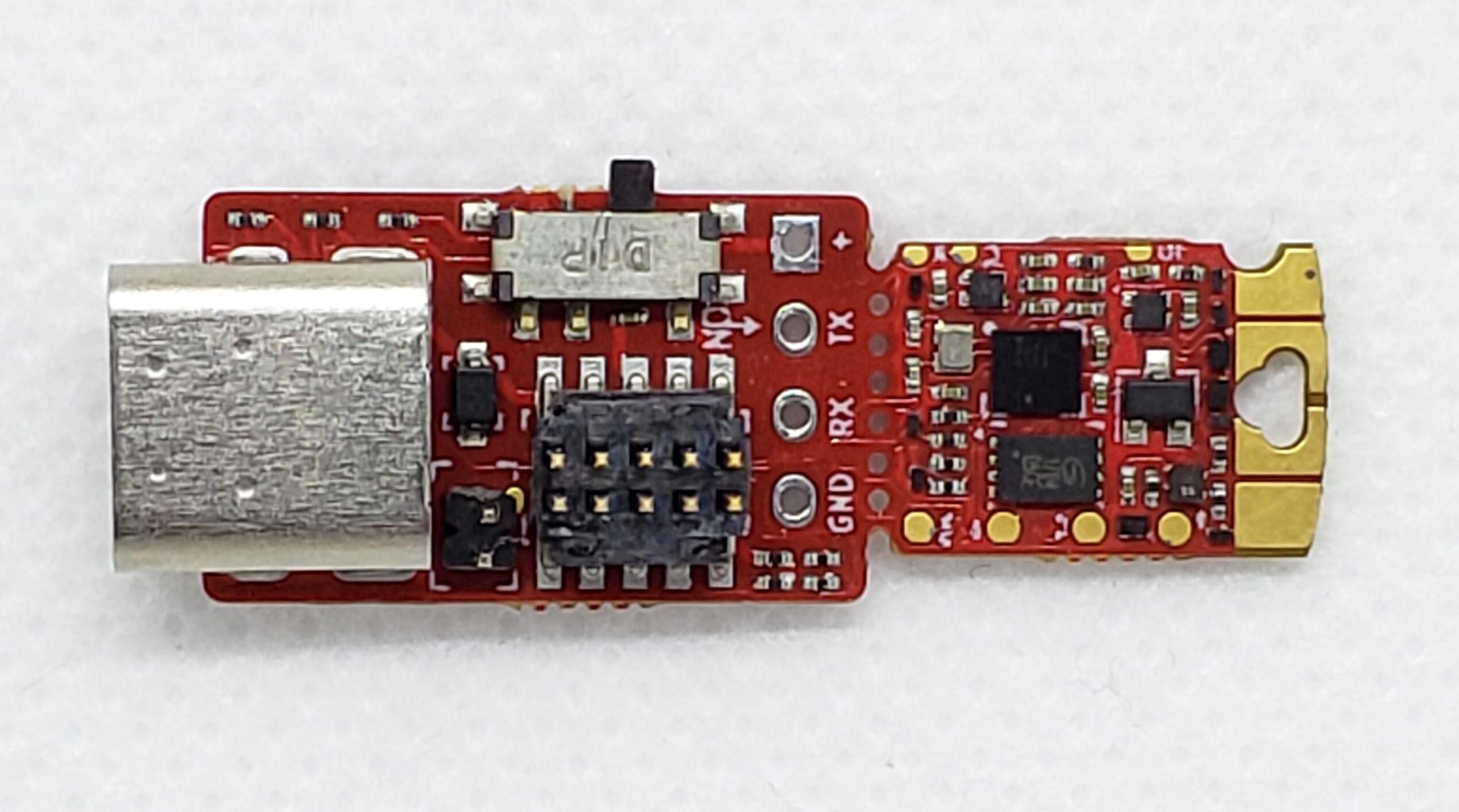
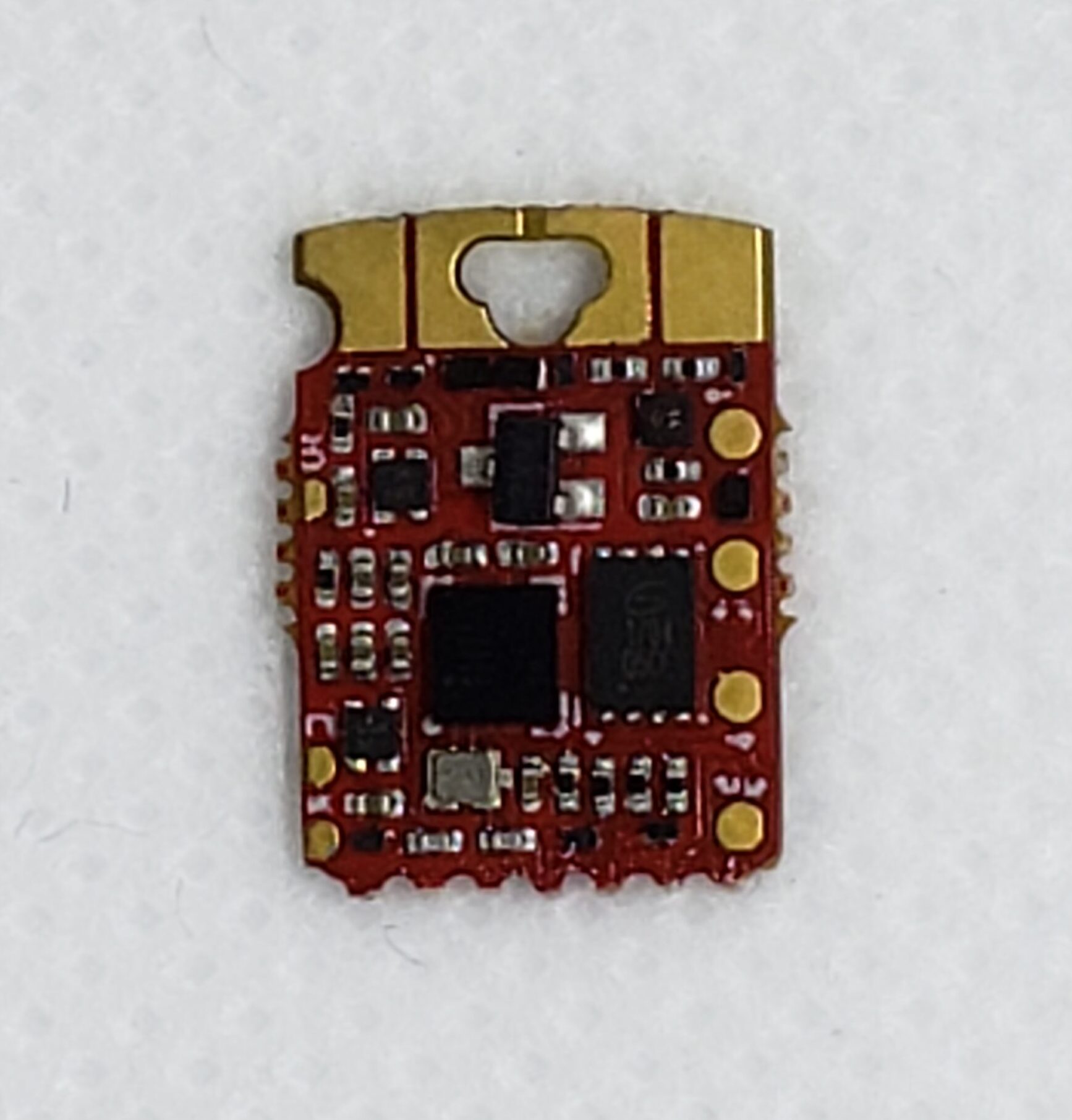
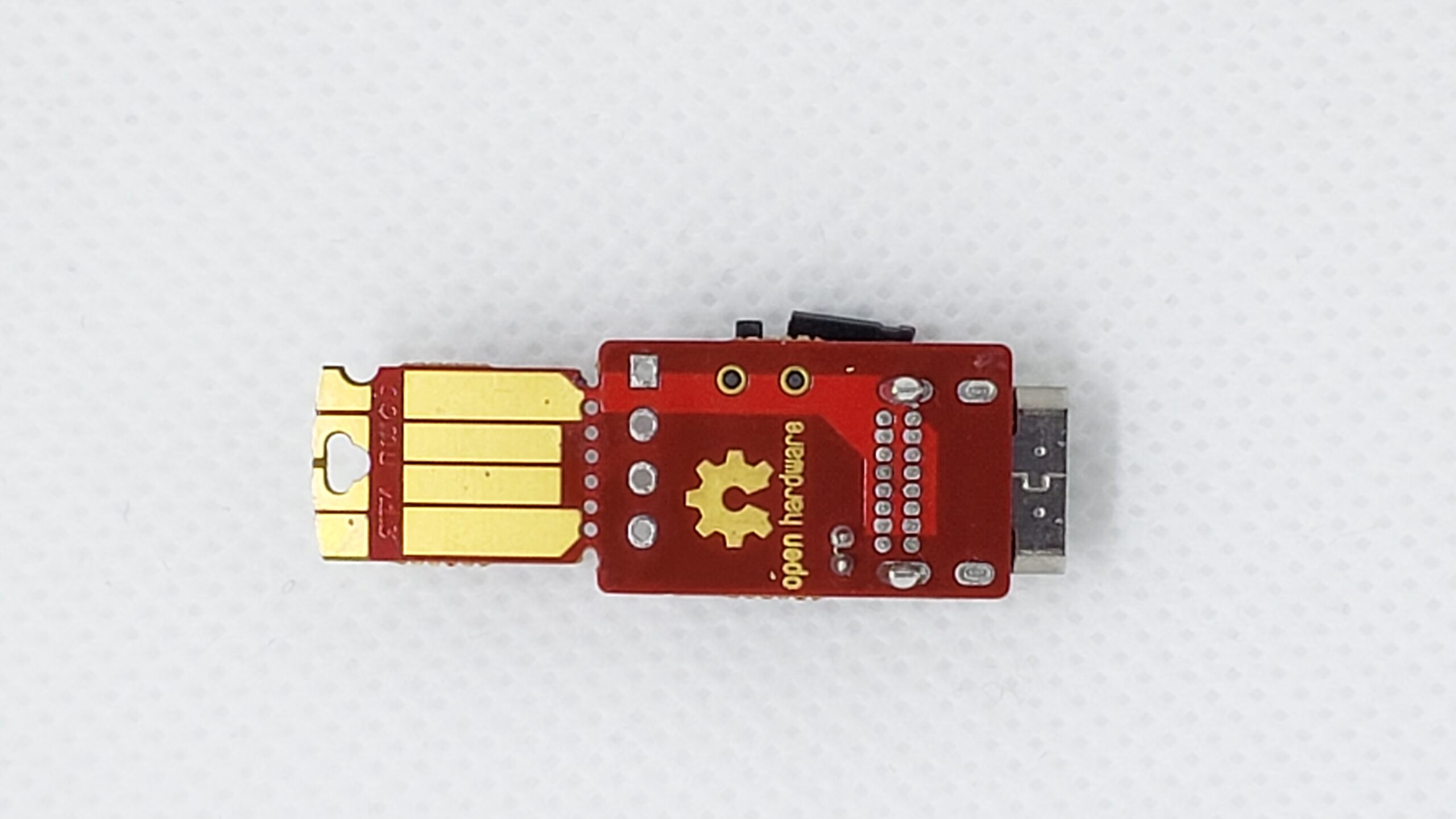
QuickLogic Corporation, a developer of ultra-low power multi-core voice-enabled SoCs, embedded FPGA IP, and endpoint AI solutions, today announced the introduction of its new Qomu development kit, a tiny form factor Arm® Cortex®-M4F MCU + eFPGA combination that fits into a USB Type A port. Optimized for the QuickLogic Open Reconfigurable Computing (QORC) initiative, the kit is supported by a wide variety of vendor-supported open source development tools, including Zephyr, FreeRTOS, SymbiFlow and Renode, which broadens access and enables designers to develop applications virtually anywhere.
Highlights:
Tiny form factor fits in USB Type A port found on almost every computer, enabling portability and development anywhere
Supported by 100% open source hardware and software tools for the MCU and embedded FPGA core
The Qomu development kit contains QuickLogic’s EOS S3 MCU + eFPGA SoC, which enables an incredible amount of processing capability for such a tiny development kit. The MCU enables seamless software development while the embedded FPGA (eFPGA) can be used to accelerate or offload algorithms from the MCU, or to simply implement custom IP or provide glue logic. While the kit can implement a wide range of functionality for a broad set of market segments, it is especially well-suited to edge IoT applications – especially those requiring ultra-low power consumption and artificial intelligence or machine learning capabilities.
QuickLogic’s QORC initiative has led to a completely open source, vendor supported development tool environment for the Qomu development kit. Open source development tools include SymbiFlow synthesis, place & route, and bitstream generation. Many example applications and gateware are readily available for free. In addition to standard Verilog support with SymbiFlow, Qomu supports nMigen for a Python-to-FPGA design flow. Additional open source tools include Zephyr, FreeRTOS and Renode.
“The Qomu dev kit is a milestone for the industry in many ways. It packs an incredible amount of functionality in the size of a USB port,” said Mao Wang, senior director of marketing at QuickLogic. “More importantly, this open source dev kit was designed in close collaboration with one of the most respected designers in the open source community,Sean Cross.”