65V Input -12Vdc Output 1A synchronous buck DC/DC converter using LM5164

This is a step-down DC-DC converter mainly designed for applications such as high-cell-count battery packs, power tools, garden tools, and electric scooters, drones. Some of the features of the project is precision enable, input voltage UVLO, internal soft-start etc. The project operates over a wide input voltage range of 15V to 65V to provide a regulated 12V-1A output at 300Khz working frequency. D1 is the power LED, and 4 Pin male header connectors provided for input and output. The full-load efficiency of the project is 90% @ nominal input voltage of 48 V and an output voltage of 12 V. The switching frequency is set by resistor R4 at 300 kHz. The output voltage soft-start time is 3 msec.

65V Input -12Vdc Output 1A synchronous buck DC/DC converter using LM5164 – [Link]

Glo – Multiple LED strip controller that is Arduino-compatible

Light-emitting diodes (LEDs) are simple components that are used as visual indicators or LED lighting. Controlling just one strip of LEDs with an Arduino Uno and the likes is not so much of a big deal for most embedded designers but installing and controlling multiple strips of LEDs, especially where they’ll be jostled around, can really be a task to handle.

Well, there are currently a number of low-cost RGB strip drivers in the market but the majority of them are not flexible and do not have external I/O. The option of using an Arduino Uno or a similar microcontroller too is not all that suitable when you’re working with rugged or compact projects.

It is to this effect that Om Anavekar designed Glo – a simple and hackable Arduino-compatible board that can help you control up to 4x independent strips with screw terminals.

“The board is smaller than an Arduino UNO and contains all the ports needed to run multiple LED strips, eliminating the need for extra wires. Additionally, it uses heavy-duty terminal blocks for the LED and power connections, ensuring that the wires won’t come unplugged in more rugged applications,” writes Anavekar. “Glo can also be powered via a power bank or smartphone wall adapter, or via a terminal block for LEDs with voltages over 5V.”

The board includes:

  • Open source Atmega328p
  • FT232 USB to Serial converter chip. (Commonly used on official Arduino boards and does not contain driver issues usually found in clones
  • Hall effect sensor. (Detects the presence of nearby magnets)
  • AMS1117 Voltage Regulator for microcontroller
  • Four addressable RGB LED channels
  • One Digital pin (D2), Eight Analog Pins (A0-A7), and Serial Transmission Pins (TX & RX). (You can use the analog pins as digital pins if needed).
  • Three GND pins, Two 3.3V pins, Two 5V, One VIN (voltage supplied by power supply) pin, and One RESET pin.
  • Mini USB serial programming port
  • Mini USB 5V power port
  • 5V screw terminal power port, and,
  • Two-mode buttons for changing settings.

The ATmega328P microcontroller in the board means countless possibilities for your lighting projects because the board can be interfaced with external modules, sensors, or processors. The board also comes with two USB ports: one for programming the processor while LEDs are plugged in while the other is for powering the LED strips. A thermal fuse was also added to prevent damages since the USB has a maximum current tolerance of 1 A.

The board was also designed to be powered through a 5V screw terminal power port that can also accept voltages between 5-12V, meaning you can use it to control LEDs with higher voltages.

Anavekar also claims that Glo can control up to 240 x WS2812B LEDs at once and should be able to handle more but he wouldn’t advise it is handled that way because “too many LEDs can cause the controller to overheat, damaging both the controller and the LED strip.” He also said it is not advisable to run all 240 LEDs at “maximum brightness continuously’ since it will take about 14.4 amps for all red, green, and blue sectors to go on full and it’s recommended to keep current usage at 10A or below. The amount of LEDs also largely depends on the power supply being used, so you have to be sure that the power supply you are using is capable of supplying the required current for your project before turning the lights on.

Glo supports an improved version of Adafruit’s strandtest program and all the test codes can be found on the project’s GitHub.

If you are interested in building one yourself, you can visit the developer’s page on instructables.com, where you will find a lot of useful resources including board design, fabrication processes, and even a nice 3D-printed case design.

You can also check Omni Labs for the WiFi-enabled Glo Rev 2 version of the board which is due to be launched on Kickstarter in March.

More flexibility and higher I/O speeds? Meet the new USB2IO interface explorer

USB2IO is a high-tech interface device that is fully powered by USB and totally dependent on STMicro STM32H7 MCU and Intel Cyclone 10 FPGA. It is an FPGA-based multi-I/O device that offers ease of working with various electronic devices using common interfaces. It is designed towards helping engineers and embedded developers communicate with various breakout boards and functional hardware blocks.

USB2IO comes with an I/O speed of 300 MHz, I/O voltage level support of 1.8V – 3.3V, 32MB RAM, 64MB ROM, a 20-pin I/O port (single I/O or 8-differential high-speed pairs), and a USB 2.0 high-speed port.

USB2IO is a USB to IO interface that combines the functionality of a protocol analyzer, a data logger, a communication interface, an embedded functional test platform, and a basic signal generator.

KEY FEATURES:

  • Upgradable FPGA and MCU firmware for control modules
  • Failsafe bootloader for safe firmware upgrade
  • Python and C++ SDKs for developer’s support (invade you need to implement automated testing for instance)

SPECIFICATIONS:

  • STMicro STM32H743 Arm Cortex-M7 clocked @ 480MHz
  • Intel Cyclone 10LP (10CL040) FPGA with 40k logic elements, 1,134 Mbit embedded memory and 126 DSP blocks
  • External 64MB QSPI flash for extra FPGA code storage
  • 32MB SDRAM for MCU and FPGA (64MB in total)
  • High-speed USB 2.0 Type-C port
  • 50 MHz oscillator
  • I/Os via 20-pin header
    • 16x GPIO single-ended mode, 8x LVDS pair mode or a mix of 2 modes depending on firmware configuration
    • 1.8V – 3.3V, LVDS 2.5V
    • 300 MHz I/O speed
    • Si570 Programmable PLL with frequency range of 10 MHz to 250 MHz
  • Power Supply
    • 5V/1.5A using USB-C interface
    • 1A max programmable LDO with voltage range 1.8V – 3.3V designed for powering external (customer’s) device
  • Operating System: Microsoft Windows OS, MacOS and Linux
  • Dimensions: 100 mm x 65 mm x 20 mm
  • Weight: 80 g
  • Certification: CE

The device is a very good lab/production tool that can be used for the following applications:

  • Communication with other electronics using I2C, SPI, I2S, PDM microphone interface, USART, RS485, CAN 2.0B bus, MDIO, and other interfaces.
  • 16-channel pattern generator via 16-pin GPIO interface
  • 8-LVDS pairs available (up to 300MHz)
  • Powering an external device with it’s 1A max programmable LDO with voltage range 1.8V – 3.3V
  • Automatic electronic functional testing
  • Data Transmission using ASCII or RAW protocol
  • Communication with Host PC using USB HID device (Virtual COM port)
  • Capture monochrome/color pictures/videos from CMOS / CCD sensors

If this interests you and you’re probably considering getting one for yourself, you can check the official website for further details on the USB2IO interface explorer including documentation, user guide, and programming guide, or better still visit Amazon.co.uk where the board sells for about $520.

Broadcom’s BCM4389 Chip with Wi-Fi 6E Technology and Bluetooth 5

Broadcom’s BCM4389 chip is a client-side device supporting Wi-Fi 6E and Bluetooth 5 combo dedicated to mobile handset applications. The Wi-Fi 6E technology can operate on the 6 GHz band with 160MHz wide channels which is a progressive version of the Wi-Fi 6 technology. Hence, it enables speeds over 2 Gbps for faster communications than the Wi-Fi 6 that supports from 2.4GHz to 5GHz radio bands.

BCM4389 chip

The BCM4389 chip is a low-power design with multi-radio Bluetooth 5 architecture compatible for BT Xstream Dual Bluetooth and Tri-Band Simultaneous (TBS) connectivity that enhances the Wi-Fi and Bluetooth functionalities for optimized battery utilization. The chip features low power consumption and small solution size. Hence, making it suitable for mobile applications with high performance and low latency requirements.

Broadcom’s BCM4389 will power the world’s first Wi-Fi 6E smartphone that is Samsung Galaxy S21 Ultra. The phone comes with the BCM4389 chip featuring a glitch-free audio experience and enhanced location accuracy. The chip comes with a power management unit that eases the system power topology. This supports the direct operation from a mobile platform battery, hence maximizing the battery life.

Low Power Robust Indoor Applications of BCM4389 Chip

Key Features of BCM4389 Chip

  • Seven Wi-Fi and Bluetooth radios
  • Support for 2 streams of Wi-Fi 6E
  • Multi-Radio Bluetooth 5 with antenna beamforming
  • Tri-Band Simultaneous (TBS) architecture including a dedicated background scan radio for Wi-Fi and Bluetooth
  • Simultaneous dual-band operation
  • 2.63 Gbps PHY rate
  • Operation in 2.4 GHz and 5.1-7.125 GHz unlicensed bands
  • 160 MHz channel bandwidth
  • 1024-QAM modulation
  • OFDMA
  • MU-MIMO

BCM4389 chip comes with a TBS connectivity architecture that supports improved Wi-Fi QoS and five times better battery utilization. Its Bluetooth 5 architecture creates robust links to audio headsets even in highly crowded areas like subway stations. The multiple input multiple output feature of the Bluetooth 5 allows body blocking immunity and solution for interference in communication.

CEO of Wi-Fi Alliance says:

“Broadcom’s chipset, among the first Wi-Fi 6E certified devices in our interoperability testbed, that powers Samsung’s Wi-Fi 6E smartphone demonstrates the industry’s rapid momentum to deliver Wi-Fi 6E benefits securely and reliably to Wi-Fi users. Hence, Wi-Fi Alliance members have mobilized around Wi-Fi 6E for recognizing the tremendous latency and performance benefits devices can deliver to Wi-Fi users”

The chip is expected to be used for AR/VR applications as it reduces latency by working at higher data rates. So, it can support UHD video streaming with a 4K resolution (3840 x 2160 pixels). It features secured connectivity for mobile hotspots for high-speed tethering use cases. It also enables robust low-power indoor use cases like homes, apartments, offices, and indoor public venues.

Applications of BCM4389 Chip

For information visit the official product page of BCM24389. Images and technical specifications have also been taken from the product page and announcement.

Ruggedized Compact Industrial PC with NXP i.MX 8M Processor

IBASE Technology Inc., a leading provider of industrial motherboards and versatile embedded solutions, is pleased to announce its ISR301 ruggedized compact computing system. Built for both industrial and commercial applications including factory automation, machine vision, edge computing, POS and digital signage, the ISR301 is powered by a quad-core NXP Cortex™ A53 i.MX 8M processor in 1.3GHz frequency. The i.MX 8M processor offers unprecedented media processing capabilities, allowing the ISR301 to deliver 4K immersive multimedia content in signage for transportation hubs, shopping malls, hotels and event venues.

The ISR301’s industrial-grade design ensures a 24/7 operation in a wide operating temperature range between -10°C and 60°C. Additionally, the fanless mini box PC with its side brackets makes it easy to securely fit in any space-constrained environments. Measuring 172mm x 162mm x 36mm (WxDxH), it has 3GB LPDDR4 system memory, 16GB eMMC flash memory, and rich connectivity via the front panel with 1x GbE RJ45, 2x USB 3.0, 1x USB OTG, 1x HDMI and 1x serial port, as well two serial ports and GPIO at the rear side. Other features include a 12V~24VDC power input and expansions slots for M.2 Key-E modules and mPCIe cards.

ISR301 FEATURES:

  • NXP Cortex™ A53, i.MX 8M Quad 1.3GHz processor
  • 3GB LPDDR4, 16GB eMMC & SD socket for expansion
  • Embedded I/O for COM, GPIO, USB, HDMI and Ethernet
  • Supports M.2 Key-E (2230) and Mini PCI-E with SIM socket for wireless/4G/LTE connectivity
  • Ruggedized and fanless design

To help customers reduce time to market and development costs, IBASE provides Board Support Package (BSP) for Android 9 and Yocto Linux v2.5 operating systems. For more information, please visit www.ibase.com.tw

u-blox – Zero compromises on cellular and GNSS performance

u-blox, a global provider of leading positioning and wireless communication technologies and services, has announced the ALEX-R5, a miniature cellular module that integrates low power wide area (LPWA) connectivity and global navigation satellite system (GNSS) technology into an ultra-small system-in-package (SiP) form factor. Comprising hardware components designed fully in-house, ALEX-R5 is based on the secure UBX-R5 LTE-M / NB-IoT chipset platform with out-of-the-box Secure Cloud functionality and the u-blox M8 GNSS chip for world-class location accuracy.

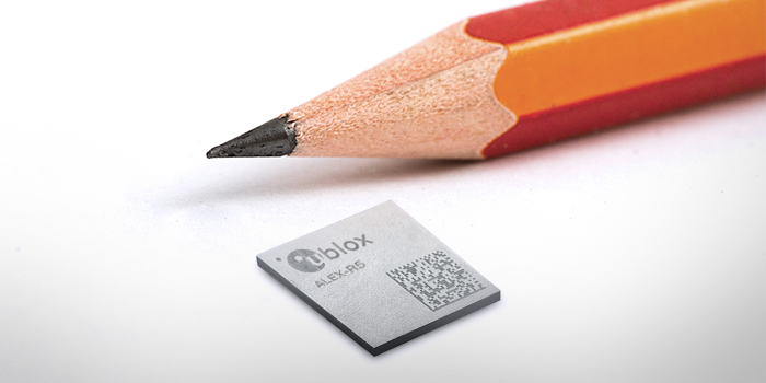
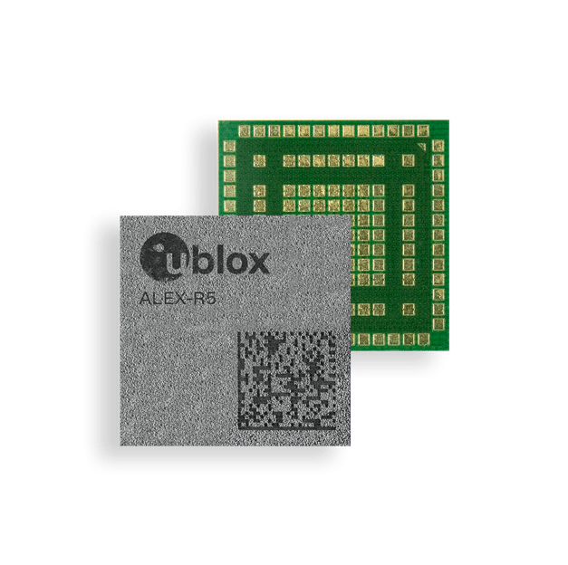
ALEX-R5 stands out for its miniature 14×14 mm footprint, achieved thanks to its SiP design, reducing its size compared to the functionally equivalent u-blox SARA-R5 module by half. Its tiny dimensions make it a perfect fit for size constrained applications.

Zero compromises on cellular and GNSS performance

ALEX-R5 makes zero performance compromises in terms of the technologies it features. Its 23 dBm cellular transmission power guarantees that end devices operate effectively in all signal conditions, even at cell edges, underground, or in other challenging scenarios. And a dedicated GNSS antenna interface enables fully independent, simultaneous operation of the u-blox M8 GNSS chip, matching the performance of a stand-alone u-blox M8 module. u-blox IoT Location-as-a-Service with CellLocate® and AssistNow (online, offline, and autonomous) further enhance positioning performance.

Optimized for power-sensitive and battery-dependent applications

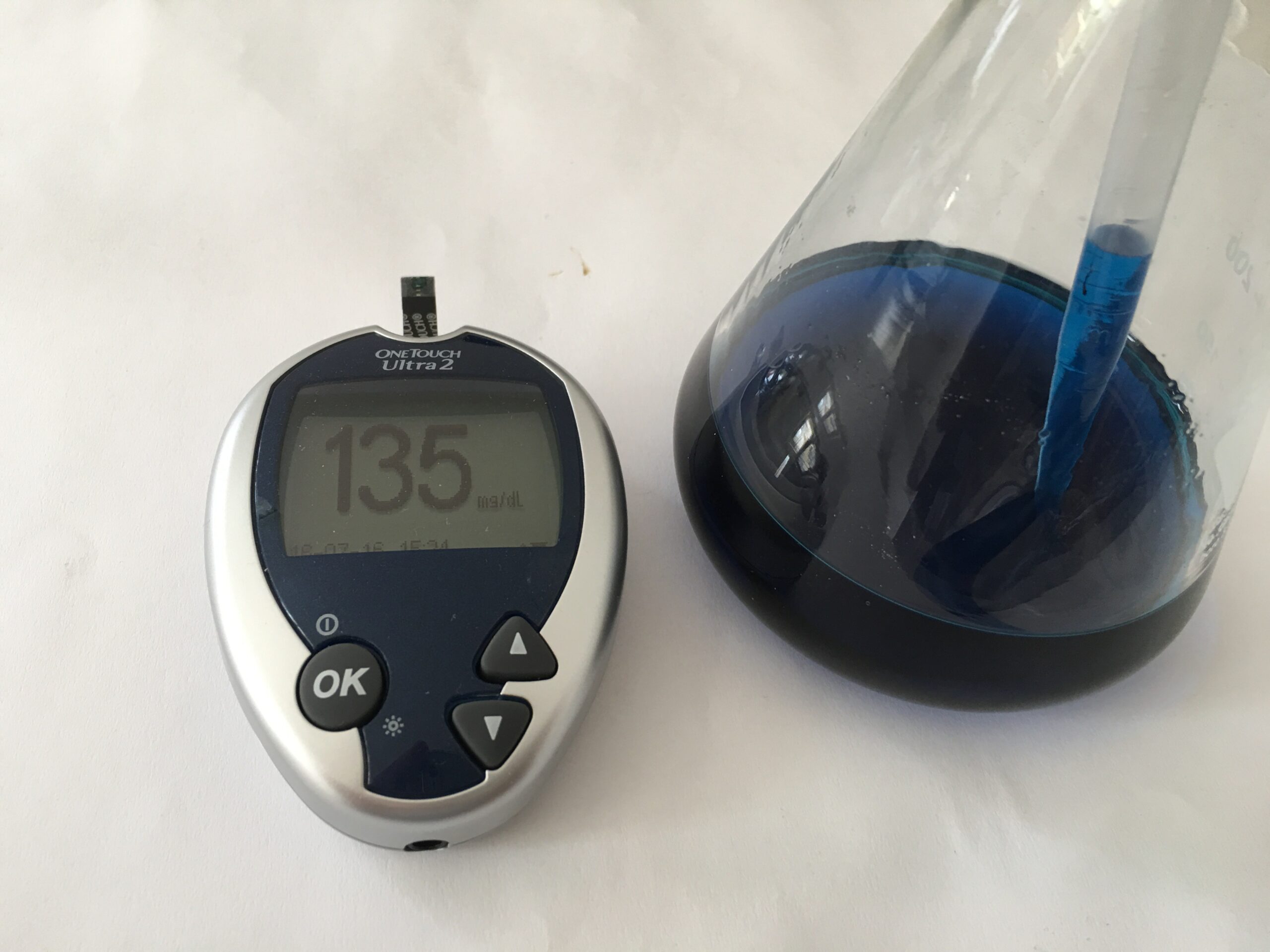
ALEX-R5 is optimized for power-sensitive and battery-dependent applications, addressing common pain points of size-constrained applications such as wearables and connected medical devices. It achieves this by leveraging the lower power modes of the u-blox UBX-R5 and UBX-M8 chipsets and giving users options to further balance power consumption and performance using GNSS Super-E mode.

Its rugged SiP construction makes it a perfect fit for harsh environments, where moisture or vibration would be a concern for conventional modules. ALEX-R5 is rated at moisture sensitivity level 3 (MSL 3), offering reduced handling and device production complexity.

Designed to last an IoT lifetime and 5G-ready

By bringing all technology building blocks in house and having full hardware and software ownership, u-blox can guarantee long-term device availability and provide lifetime support for the entire platform, down to the chipset level. Secure Cloud functionality supporting IoT-Security-as-a-Service based on an internal, hardware-based secure element enables a lightweight pre-shared key management system specifically designed for LPWA devices.

ALEX-R5 future-proofs IoT devices and solutions by enabling customers to software upgrade deployed devices for compatibility with 5G networks, offering a seamless transition to the next generation of cellular technology as 5G networks are rolled out by mobile operators.

Engineering samples of the ALEX-R5 SiP will be available by Q1, 2021.

Meet the $4 Raspberry Pi Pico Board with RP2040 Dual-Core Cortex-M0+ microcontroller

After we saw the launch of the Raspberry Pi 4 from the Raspberry Pi Foundation back in 2019, we are pleased to announce that the company has not rested on their oars as they have created their own microcontroller board called Raspberry Pi Pico, designed for not only the educationist or hobbyist but also for commercial products. The most interesting thing about this new board is that it is powered by an RP2040 dual-core Cortex-M0+ microcontroller designed by the foundation itself.

Let’s quickly talk about the RP2040 microcontroller. The name “RP2040” microcontroller is quite a unique one:

  • RP is short for Raspberry Pi,
  • 2 – the number of cores
  • 0 – the MCU core used (Cortex-M0+)
  • 4 – floor(log2(ram/16k)) formula to calculate a number representing the SRAM
  • 0 – floor(log2(non-volatile/16k)) formula for non-volatile storage capacity inside the chip.

The Raspberry Pi Foundation probably decided to create a custom MCU to prevent people from copying the hardware too easily and using their software. It could also be that they wanted to sell the RP2040 microcontroller to makers who are looking to design their own boards/projects with it because from updates being received, third party RP2040 boards have been announced by Arduino, Sparkfun, Adafruit, and Pimoroni already.

Now, to the Raspberry Pi Pico board itself. As we mentioned earlier, the Raspberry Pi Pico is based on the RP2040 microcontroller. It is a low-cost, high-performance microcontroller board with 2x ARM Cortex-M0+ cores run up to 133MHz, 256KB RAM, 30 GPIO pins, 2MB of onboard QSPI Flash memory for code and data storage, and a broad range of interfacing options. The only downside to this board is that the pins support only 3.3V, and there’s no 5V tolerance.

Raspberry Pi Pico Specifications:

  • Raspberry Pi RP2040 dual-core Cortex-M0+ MCU @ 48 MHz (maximum of 133 MHz) with:
    • 264 kB of embedded SRAM in 6 banks
    • 30x multifunction GPIO
    • 6x dedicated IO for SPI Flash
    • Dedicated hardware for commonly used peripherals
    • Programmable IO for extended peripheral support
    • 4 channel ADC with an internal temperature sensor, 0.5 MSa/s, 12-bit conversion
    • USB 1.1 Host/Device
    • SWD Debug interface
    • Package: QFN56 7x7mm
  • 2MB QSPI flash
  • 1x Micro USB 1.1 port (for power and programming)
  • 2x 20-pin 2.54mm pitch header and castellated holes with 26x GPIOs, 3x 12-bit ADC, 2x UART, 2x I2C, 2x SPI, 16x PWM and 2x programmable high-speed I/O
  • 3.3V I/O voltage
  • 12-bit temperature sensor
  • 3-pin Arm SWD port
  • BOOTSEL button
  • User LED
  • 1x Timer with 4x alarms
  • RTC
  • 5V via Micro USB port or 2V – 5V DC via VSYS pin
  • Dimensions: 51 mm x 21mm

The board doesn’t come with headers so you might have to solder them yourself or better still, buy the version with soldered headers.

Software support for the board is MicroPython and C/C++ programming with the command line or Visual Studio Code. Both the MicroPython and C/C++ SDK as well as hardware and software details are all available on the company’s Github. You’ll also find a “Get Started with MicroPython on Raspberry Pi Pico” manual provided by the company to help younger makers in their development journey.

Raspberry Pi Pico is currently selling for $4 without shipping. You can also choose to buy the version of the board with pre-soldered headers or the Basic kit that has a Pico board or the one that doesn’t. All versions of the board are available on RS Components, Cytron (ASEAN only), and Seeed Studio.

PICAN-M: NMEA 2000 on the Raspberry Pi for Marine Applications Made Possible

If you ever worked with a GPS location module in close proximity with the hardware, you might have an idea about the direction we are taking today, as you had to deal with NMEA strings. NMEA 2000 (or NMEA2K or even N2K) is something among those lines but emphasizes a bit more on the hardware than the former. It intends to be a plug-and-play protocol to connect devices inside marine vehicles, including sensors and display units. Electrically, it is compatible with the CAN protocol. Typical data exchanges within the NMEA 2000 protocol include position, GPS status, steering commands with autopilots, wind sensor data, among other important variables in the aquatic environment. Now that you have a vague idea of what it is, let us introduce you to an interesting HAT for the Raspberry Pi, the PICAN-M.

The PICAN-M is a Raspberry Pi HAT for location, which can be connected through NMEA 2000 or NMEA 0813. Along with the expected location functionalities, it provides you with a 3 A switch-mode PSU, so that you can power both the HAT and the Raspberry Pi from an on-board 12 V power source. Now, if you know anything about the Raspberry Pi hardware, your first question (like mine) is going to be: “how do I communicate with the HAT?”, because the communication on the Raspberry Pi is limited to UART, I2C, and SPI. There is no CAN. The easy answer is they added a CAN controller to the HAT (more specifically, the MCP2515 part) which communicates via SPI, so all you need is the CAN utils package and you are good to go. But you are not limited there, the NMEA 0183 allows communication via UART. It requires some extra effort, but if your application requirements leave you with no choice, you can still use it.

The PICAN-M all plugged in through CAN

Let us take a look at its specifications:

  • CAN bus connection via Micro-C connector
  • SocketCAN driver (appears as can0 to application)
  • NMEA 0183 (RS422) connection via 5-way screw terminal (appears as ttyS0 to application)
  • Qwiic (I2C) connector for extra sensors
  • 3A Switch Mode Power Supply
  • Compatible with OpenCPN, OpenPlotter, SignalK, and CANBoat

Now, we will take a look at the module in action. Of course, we will not go crazy and drive a boat. Firstly, we cannot, lockdown. Then, we have no module or boat license (or boat). So, we dove through its manual. It is not a bad experience, does not give you nausea from the sea and the documentation is actually pretty good. The image you are seeing is of the OpenCPN. There are more options, and the module only shines further if you put the I2C port to good use (by plugging a barometric pressure, humidity, and temperature sensor, like the BME280, from SparkFun). Lastly, the pricing of $98.85 is acceptable, considering the functionalities it provides you with.

OpenCPN interface powered by the HAT

PICAN-M link: https://copperhilltech.com/pican-m-nmea-0183-nmea-2000-hat-for-raspberry-pi/

DC Electronic Load to Banana Adaptor

DC Electronic Load to banana cable adaptor

This product is a multi-purpose DC load terminal to banana cable adaptor. It includes solder pads for direct soldering of harnesses to the DC load output (convenient to add voltage sensing wires or wires from a power supply for battery emulation). Additionally, it has a fully integrated low-side shunt current sense circuit, locally filtered and outputted on a BNC connector. This allows viewing of the current waveform directly on your scope with extremely low noise.

This product is ideal for anyone that works with fast load or current transients and would like to observe those on an oscilloscope.

Options

This product can be sold in two options:

  • [Adaptor only] The adaptor board is shipped only with banana connector mounted. The board can be used out of the box as a DC load terminal to banana cable adaptor and solder pads. The current monitor circuit (BNC connector, shunt resistor and low pass filter) are left unmounted. The buyer is free to mount his own BNC connector (J3: 5-1634503-1) and preferred shunt resistor (R1: LVK24) and low pass (C1, R2: 0805 size).
  • [Adaptor with current monitor] The adaptor board is shipped fully mounted with a 20mOhm/1W shunt resistor, 16kHz low-pass filter (1kOhm, 10nF) and the BNC connector installed. This corresponds to 20mV/A rated for 7A. This is the ideal option if you would like to observe load or current transients on an oscilloscope.

You can buy the adaptor on Tindie for 5.00 + shipping.

Open source Arduino blood glucose meter shield uses electrochemical test strips

Diabetes is a serious disease that affects millions of people around the world today. Diabetes affects the body’s ability to produce insulin, a hormone that enables the body to turn glucose into sugar which has resulted to a large number of deaths, an estimate of 1.6 million deaths yearly caused by the illness. This is why it is very important such illness should be diagnosed early for effective management, because if left untreated, it can lead to heart disease, kidney damage, nerve damage, and stroke. This has led Markus Bindhammer to embark on an open source blood glucose meter shield project. This project competed and won an award at the Assistive Technologies category of the 2016 Hackaday prize. The glucose meter plays a large part in effective control, as this provide patients with the ability to monitor blood glucose levels from the comfort of their homes. You can obtain the glucose meter at your local val pharmacy. It is easy to use, the patient insert one of the disposable test strips into the meter, prick their finger, load a droplet of blood into the test strip, wait a few seconds and get an instant reading of the current blood glucose level. .

Designed by M.Bindhammar, the aim of the project is to measure blood glucose level using electrochemical test strips. The glucose meter shield functions by receiving blood sample through a one touch Ultra test strip and output the results on the Arduino IDE serial monitor window. The test strip features three electrodes which are printed into the test strips. They include: a reference electrode, a counter electrode and a working electrode. A fixed voltage is supplied, and the resulting current after the blood is added is monitored. The response it give is then measured to the glucose concentration through calibration. You should note that some models requires a user to manually enter a code found on a chip that comes with the test strip since test strips can vary from batch to batch. This code enables the meter to be calibrated to a particular batch of test strips. The brand of test strips used is the ONE-TOUCH which has standardized test strips around a single code number so for a particular set there is no need to change code in their older meters and some of their newer meters.

The electrodes of the strips are coated enabling an enzymatic chemical reaction to take place on the surface of the electrode, and this reaction determines the resulting current. We find little details about electrochemistry, and details available can be quite complex. Also some companies do not release detailed data about their particular test strips operation. But some devices functions by watching the current after a short initial transient (the current will level out to some degree) and then report the current after a fixed time. Others examine the total amount of a reaction that has occurred and thus integrates the current with regard to time in order to obtain the total amount of chemical reaction that has occurred. However, the Open source Arduino blood glucose meter functions by making two measurements to determinate which relates more strongly to the glucose level: one is the current after a fixed time and the other is the total integrated current.

Markus Bindhammer owns all of the design’s intellectual property rights and is responsible for end-user support. About production and sales, Seeed says

“If the Groupbuy meets the target quantity within the allotted timeframe, the Groupbuy is deemed a success, and Seeed will initiate the production and delivery of the goods after payment is made.If the Groupbuy fails Seeed will refund all buyers within 10 working days.”

You can find more information about glucose meter shield on Seeedstudio, and Hackaday.

Video

TOP PCB Companies