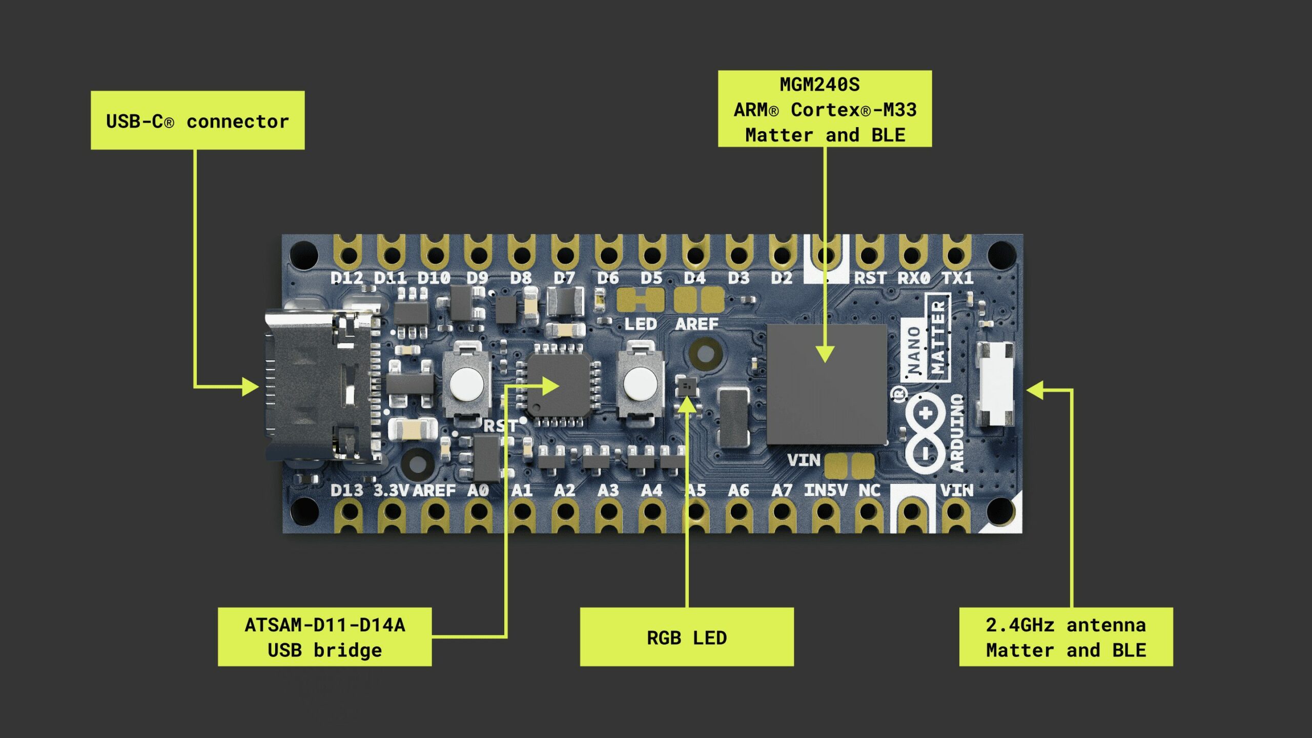
Arduino has just announced their new Arduino Nano Matter Board, powered by a SiLabs MGM240SD22VNA MPU. The MPU features a 32-bit Arm Cortex-M33 core with DSP and FPU, enhancing its performance.
The board supports various connectivity options, including Matter, OpenThread, BLE, and Bluetooth Mesh. Additionally, it features 12-bit ADCs, two DACs, I2C, UART, SPI, and PWM channels. The design includes castellated pins for easy SMD soldering onto custom carriers.
The Arduino Nano Matter features a USB-C port for power and data, with additional IN5V and VIN pins to provide external power. it also includes a JTAG/SWD debug port for troubleshooting.
Arduino Nano Matter Board Specifications:
MPU: SiLabs MGM240SD22VNA
MCU Core: 32-bit Arm Cortex-M33 with DSP and FPU, clocked at 78 MHz
Users can program using the Arduino Desktop IDE, Web Editor, or Arduino Cloud, with tutorials and sketches available for easy setup and to explore the board’s capabilities.
Arduino provides comprehensive documentation for the Nano Matter Board, including a user manual available on the Arduino Docs website. For more detailed information about the board’s specifications, you can explore the documentation further.
You can find the board listed at $25.00 on the Arduino products page but it’s not available right now and you have to join the waitlist.
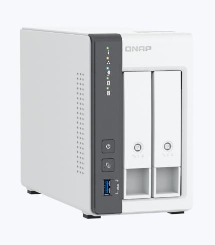
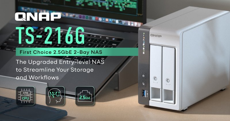
The QNAP TS-216G NAS, by QNAP Systems, Inc., features both a GbE port and a 2.5GbE port with hot-swap functionality. It promises efficient data management and enhanced reliability.
The NAS is built around a 64-bit Arm quad-core processor, with 4 GB RAM and an NPU for AI tasks. The company is utilizing this NPU to enhance image recognition capabilities in the QuMagie photo management system.
The TS-216G supports centralized file management, can use the 2.5GbE port for sharing and syncing, and runs media streaming and surveillance systems. This makes it a versatile private cloud solution.
We have written about many different NAS systems in our previous articles, including the TerraMaster, FriendlyELEC CM3588 NAS Kit, and ZimaCube NAS. Feel free to check those out if you are looking for a NAS.
The TS-216G, running on QTS 5.1, offers applications like File Station, Hybrid Backup Sync, and Qsync for easy management, backup, and synchronization. It handles multimedia content and is energy-efficient, consuming 4.973W in sleep mode and 13.907W in operation, with a 120mm fan for temperature stability.
QNAP TS-216G NAS Specifications
Processor: 64-bit Arm quad-core
Memory: 4GB on board (non-expandable)
Storage:
2x 3.5” SATA 6Gb/s, 3Gb/s HDD or SSD
Connectivity:
1x 2.5G/1G/100M LAN port
USB Ports:
2x USB 2.0 port
1x USB 3.2 Gen 1
Features:
Hot-swappable HDDs
Wake-on-LAN
1x Fan 120mm, 12VDC
Power: Minimum 65W adapter (12VDC), 100-240VAC
Operating Temperature: 0℃ to 40℃
Dimensions: 6.5 × 4.02 × 8.69 inches
Weight: 3.2 lbs
Form Factor: Tower
At the time of writing the company has not provided any pricing information about the product yet you can check out the product announcement page or the product page.
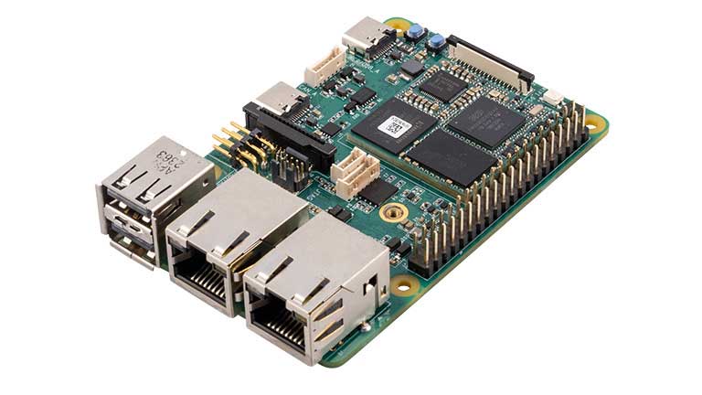
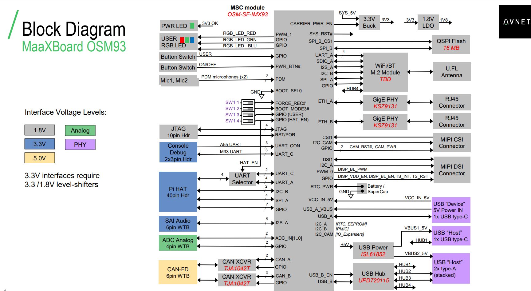
Avnet MaaXBoard OSM93 is a NXP i.MX 93 Cortex-M55/M33 AI SoC powered SBC in a Raspberry Pi from factor. The SBC is built around a Size-S OSM module and supports different Raspberry Pi HATs.
This SBC is equipped with 2GB LDDR4 and 16GB eMMC flash, and MIPI CSI and DSI interfaces for the camera and display modules. It also includes dual gigabit Ethernet ports and offers WiFi 6, Bluetooth 5.3, and 802.15.4 connectivity options. Additionally, the board features three USB 2.0 ports and two CAN FD interfaces, complete with onboard transceivers.
The NXP i.MX 93 is a Cortex-A55 and Cortex-M33-based SoC manufactured with a 16/12nm FinFET class process. This SoC includes “Energy Flex” which can optimize power by turning on/off specific blocks in the processor. The Cortex-A55 acts as a main CPU and is used to run Linux, the Arm Cortex-M33 processor handles all real-time operations and control and it can run FreeRTOS if programmed.
This is not the first SBC from Avnet, In 2019 Avent released their first MaaXBoard after that we saw they released the MaaXBoard 8ULP, MaaXBoard Nano, NXP i.MX 8M Mini, feel free to check those out if you are interested in the topic.
To get started with this board, Avnet provides support through a Yocto-based Linux board support package (BSP) and a range of example designs. The company also offers MIPI-DSI LCD touch panels, a 5V/3A USB-C power supply, and an M.2 wireless module.
At the time of writing, the Avnet MaaXBoard OSM93 (part number AES-MAAXB-OSM93-DK-G) is not yet available and is expected to be launched in Q2 2024. For more details, you can check out the product page or press releases page.
Developer Rop Gonggrijp has developed an “unofficial library” specifically for Heltec Automation’s popular development boards based on the Espressif ESP32-S3 chip, addressing the challenges developers face with the original software.
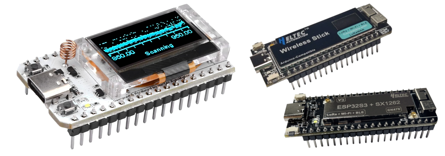
According to Heltec documentation, this board is internally known as HTIT-WB32LA and commercially as WiFi LoRa 32(V3) or ESP32 LoRa v3. It’s a very versatile board and features Wi-Fi and Bluetooth connectivity, a 128×64 pixel OLED display, and an SX1262 863-928MHz LoRa Radio. But even with all this hardware’s features, Gonggrijp found the provided software lacking in clarity, organization, and documentation, with some parts requiring significant adjustment.
In his GitHub Repository, he mentions –
The hardware is cool, but the software that comes with it is not so much to my taste. There are multiple GitHub repositories, and it’s initially unclear what is what, they use some radio stack of unknown origin, code-quality, and documentation varies, some examples need tinkering and what could be a cool toy could easily become a very long weekend of frustration before things sort of work.
Gonggrijp’s library incorporates a modified version of RadioLib for the HTIT-WB32LA and its Wireless Stick(V3) variant which has a smaller 64×32 OLED display. It facilitates easy management of the display, buttons, onboard LED, battery charging functionality, and the CPU’s deep-sleep modes.
Heltec ESP32 LoRa Dev Board Specifications:
Heltec ESP32 LoRa v3 Board: Features Espressif ESP32-S3, WiFi, Bluetooth, 128×64 OLED, and SX1262 radio.
Variants: Wireless Stick(V3) with 64×32 OLED and Wireless Stick Lite(V3) without display.
Connectivity: USB-C, CP2102 USB serial chip, Semtech SX1262 transceiver.
Power: 3.7V LiPo battery charging circuit.
Rop Gonggrijp’s Library: Unofficial library with tested sample code for easier development.
RadioLib Fork: Includes RadioLib for radio control, display, buttons, LED, and power management.
Custom Board Definitions: Simplifies Arduino IDE setup with correct partition table configurations.
Energy Efficient: Deep sleep modes and LED brightness control for power saving.
Developer Support: Installation guide, examples, and GitHub repository for support and updates.
Gonggrijp notes, however, that his library for the Heltec ESP32 LoRa Dev Board is tailored for these specific boards and might not be directly compatible with other devices, even those from Heltec. Nevertheless, developers could adapt the library or use parts of its code for other projects. The library is freely available on GitHub under the MIT license, offering a resource for developers, to quickly get started with these boards without the initial frustration.
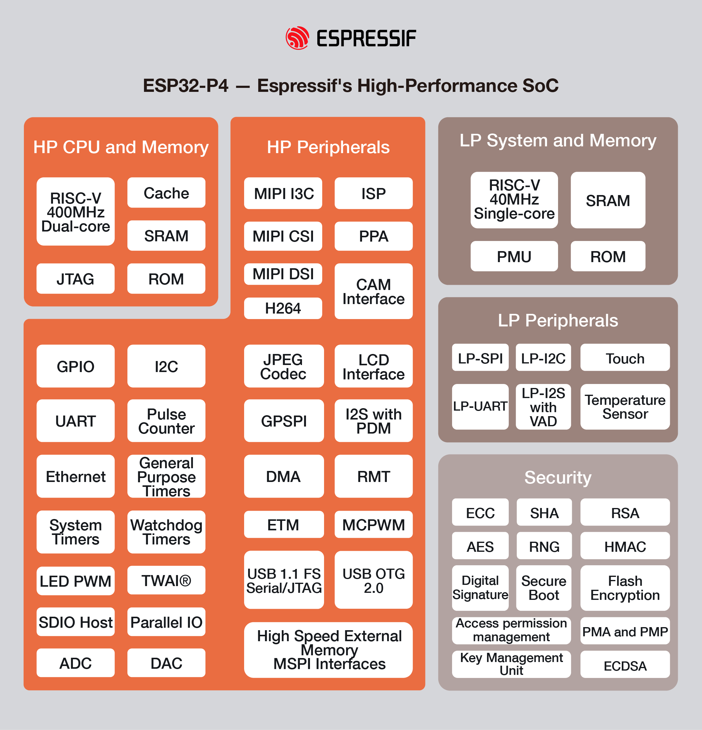
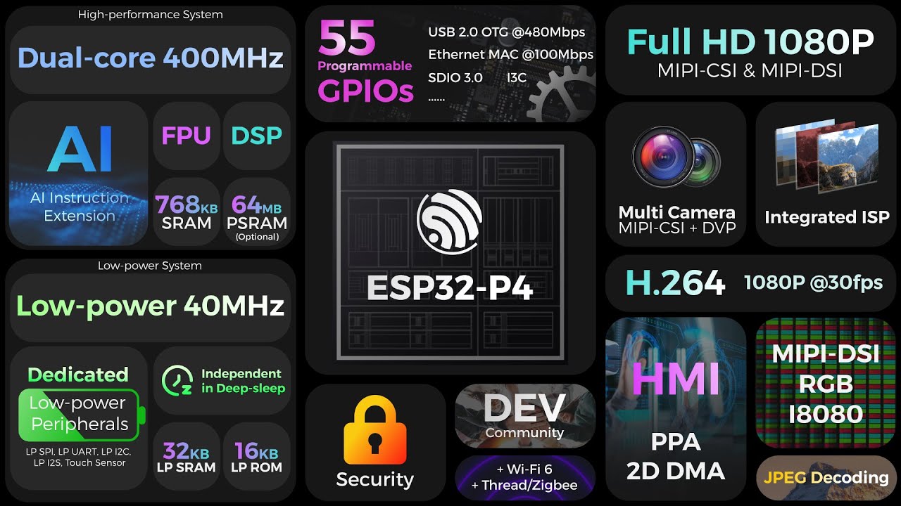
Espressif Systems just announced their latest and greatest module the ESP32-P4. The most interesting thing about this SoC is that it doesn’t have a Radio Module built-in, meaning No Wi-Fi or Bluetooth capabilities. Other than that it features a new RISC-V dual-core CPU clock at 400MHz with a newly designed AI instructions extension, an advanced memory subsystem, and integrated high-speed peripherals designed for edge computing and AI tasks.
Just last year in 2023 we saw Espresif launched SoCs like ESP32-C3 and ESP32-C6 and after that initial launch, we saw many different development boards getting built on top of those new modules. Then, in January this year, they launched ESP32-C61 A powerful SoC with advanced wireless capabilities.
Since the launch of ESP8266, this is the first time we have seen an ESP module without a Radio Module built in. But they make up for those with a ton more added features like MIPI-CSI and MIPI-DSI for camera and display interfaces, dedicated LP-Core for ultra-low-power applications, Flash Encryption, cryptographic accelerators, and a Digital Signature Peripheral with a dedicated Key Management Unit and to top thing off it has 50 Programmable GPIO and many more…
Espressif ESP32-P4 SoC Specification:
CPU: Dual-core RISC-V, up to 400MHz with AI instruction extensions and an additional LP-Core for low-power operations up to 40MHz
Memory:
768KB on-chip SRAM, expandable with external PSRAM
8KB zero-wait TCM RAM for critical data processing
Security:
Secure Boot, Flash Encryption
Cryptographic accelerators (SHA, ECC, TRNG)
Digital Signature Peripheral with Key Management Unit for enhanced security
Hardware access protection with Access Permission Management and Privilege Separation
Connectivity:
Over 50 programmable GPIOs
Supports SPI, I2S, I2C, LED PWM, MCPWM, RMT, ADC, DAC, UART, and TWAITM
USB OTG 2.0 HS, Ethernet, SDIO Host 3.0
Capable of wireless connection as a companion chip or Host MCU for various solutions
Human-Machine Interface (HMI):
MIPI-CSI with integrated ISP for camera interface
MIPI-DSI for display interface, along with parallel display and camera interfaces
Capacitive touch inputs and speech recognition
Media Support:
Hardware accelerators for media encoding (including H.264 support)
Integrated Pixel Processing Accelerator (PPA) for GUI development
Espressif recommends using their ESP-IDF programming framework for development with this module. Currently, there is no Arduino support, but it may be introduced soon, given the comprehensive documentation available for this new module.
Espressif has also launched a development board based on this new chip. Interestingly, in my search for more details about this new IC, I came across a Chinese manufacturer showcasing both the new ESP32-P4 chip and its associated development board. The video is attached below.
At the time of writing, there is not much information available for purchase but more details about this product can be found on Espressifs press release page.
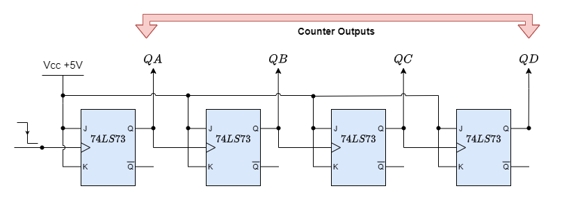
“Asynchronous counters” are those counters in which where various flip-flops are driven by various clock signals at their clock inputs. Only the first flip-flop in an asynchronous counter is externally synchronized using a clock pulse; all subsequent flip-flops in the counter use the output of the preceding flip-flop as their clock input. Asynchronous counters employ flip-flops wired in series to give the impression of a ripple in the input clock pulse.
Fig-1: Asynchronous Counter
An asynchronous counter is perfect for use in frequency division applications since it may have 2n-1 different counting states, such as MOD-16 is a 4-bit counter, which counts from (0-15). However, the fundamental asynchronous counter setup may also be used to create unique counters with counting states that are less than their maximum output number, and they are termed as MOD counters or modulo.
An asynchronous counter with truncated sequences may be created by forcing the counter to reset itself to zero at a predefined value. Then, an n-bit counter with a modulus less than the maximum value is referred to as a truncated counter, while an n-bit counter that counts to its maximum modulus (2n) is termed a complete sequence counter.
However, why would we wish to construct an asynchronous truncated counter that isn’t a MOD-4, MOD-8, or another modulus raised to the power of two? The answer is that we can by utilizing combinational logic take advantage of the asynchronous inputs on the flip-flop.
It is possible to create a decade (divide-by-10) counter output for use in common decimal counting and arithmetic circuits by modifying the modulo-16 asynchronous counter with extra logic gates.
More precisely, these counters are called “Decade Counters.” When the output count hits the decimal value of 10, or when DCBA = 1010, a decade counter must be reset to zero. To accomplish this, we must send this condition back into the reset input. Although binary decade counters are more frequent, a counter with a count sequence ranging from binary “0000” (BCD = “0”) to “1001” (BCD = “9”) is commonly referred to as a BCD binary-coded-decimal counter since its ten-state sequence is that of a BCD code.
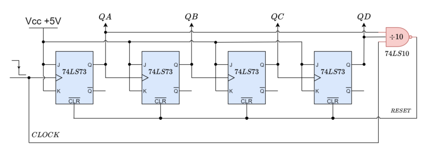
Asynchronous Decade Counter
Fig-2: Decade Counter
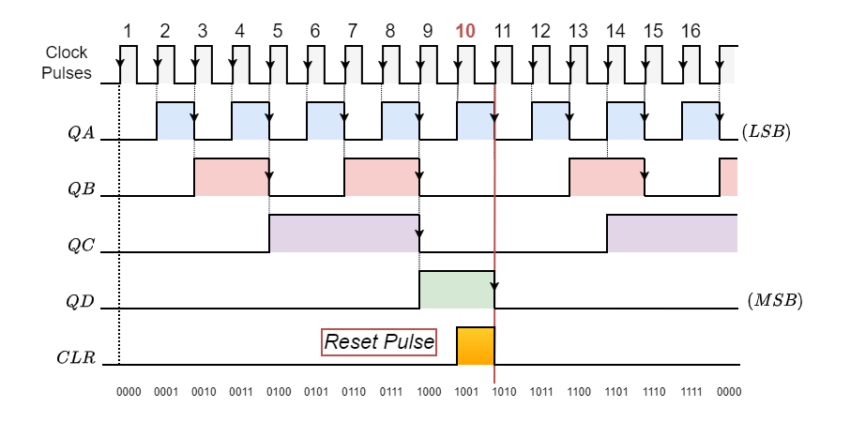
Starting from 0000 and counting higher on each trailing edge of the input clock signal, this kind of asynchronous counter continues until it reaches an output of 1001 (decimal 9). QA and QD’s outputs are now equivalent to logic “1”. When the subsequent clock pulse is applied, the 74LS10 NAND gate’s output switches from a logic “1” level to a logic “0” level.
This signal resets all the Q outputs to binary 0000 on a count of ten since the output of the NAND gate is linked to the CLEAR (CLR bar) inputs of each 74LS73 J-K Flip-flop. The NAND gate’s output goes back to a logic level of “1,” since outputs QA and QD are now both equal to logic “0” due to the flip-flops having just been reset and the counter resumes at 0000. Now, we have a Modulo-10 up-counter or a decade.
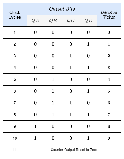
Decade Counter Truth Table
Fig-3: Decade Counter Truth Table
Decade Counter Timing Diagram
Fig-4: Decade Counter Timing Diagram
The above circuit might be readily modified to accommodate other counting cycles by utilizing the same concept of truncating counter-output sequences and altering the connections to the NAND gate’s inputs or by utilizing different logic gate combinations.
For instance, a scale of twelve (modulo-12) may be created with ease by only feeding the NAND gate’s inputs from the outputs at “QC” and “QD,” keeping in mind that output “QA” is the least significant bit (LSB) and that 1100 is the binary equivalent of 12.
Since 2n is the greatest modulus that can be achieved with n flip-flops, you should choose the lowest power of two that is larger than or equal to your desired modulus when creating truncated asynchronous counters.
Suppose we want to count from 0 to 39, or mod-40. Then, six flip-flops would be the maximum number needed (n = 6), which would result in a maximum MOD of 64. Five flip-flops would not be sufficient since this would only provide a MOD-32, we can verify the same by using the 2n formula.
Assuming we were to construct a “divide-by-128” counter for frequency division, we would require seven flip-flops to cascade since 128 equals 27. Even with twin flip-flops like the 74LS74, four integrated circuits would still be required to furnish the circuit.
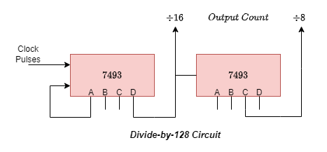
Fig-5: Divide-by-128 Circuit
Making a four-bit ripple counter by using two TTL 7493S would be a simple substitute technique. TTL 7493S is a 1:16 counter which can be split into 1:2 and 1:8. One 7493 might be set up as a “divide-by-16” counter and the other as a “divide-by-8” counter because 128 = 16 x 8. As indicated, the two integrated circuits would be cascaded together to provide a “divide-by-128” frequency divider.
Naturally, there are conventional integrated circuit asynchronous counters out there. For example, the TTL 74LS90 programmable ripple counter/divider may be set up to divide by two, divide by five, or in any combination of the two. There are several “divide-by” choices available for the 74LS390, an extremely versatile dual-decade driver integrated circuit. These combinations include divide-by-2, 4, 5, 10, 20, 25, 50, and 100.
Frequency Dividers
Because ripple counters may truncate sequences to create a “divide-by-n” output, they are particularly useful as frequency dividers, bringing a high clock frequency down to a more manageable number for use in timing and digital clock applications. Let’s take an example where we need to run a digital clock on an exact 1Hz timing signal.
With a standard 555 timer chip set up as an Astable-Multivibrator, we could easily generate a 1Hz square wave signal. However, the manufacturer’s data sheet informs us that the 555 timer typically has a 1-2% timing error, depending on the manufacturer, and that this 2% timing error is not good at low frequencies like 1Hz.
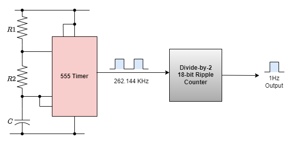
The data sheet also states that the 555 timer’s highest working frequency is around 300 kHz, and at this high frequency—which is still rather significant at a maximum of 6 kHz—a 2% inaccuracy would be acceptable. Therefore, we may simply create a precise 1Hz timing signal as shown below by using a higher timing frequency, such as 262.144kHz, and an 18-bit ripple (Modulo-18) counter.
1Hz timing signal from an 18-bit asynchronous ripple counter
Fig-6: 18-Bit Ripple Counter
Naturally, this is a very basic example of how to create precise timing frequencies. However, precision frequency generators can be created for a wide range of uses, including watches, clocks, event timing, electronic pianos and synthesizers, and music-related applications, by utilizing high-frequency crystal oscillators and multi-bit frequency dividers.
Unfortunately, one of the primary drawbacks of asynchronous counters is that, because of the internal circuitry of the gate, there is a slight delay between the arrival of the clock pulse at its input and its presence at its output.
The term “propagation counter” refers to this delay in asynchronous circuits, and in certain high-frequency scenarios, it might result in erroneous output for the asynchronous ripple counter.
A significant time gap may occur between the input signal and the counted output signal in big bit ripple counter circuits if the delays of the individual stages are combined up to produce a summed delay at the end of the counter chain. Hence, in high-frequency counting circuits involving many bits, the asynchronous counter is typically not utilized.
Additionally, because of its clocking sequence, the counter’s outputs do not occur at the same instant in time or have a set temporal connection with one another. Stated differently, there is a cascading effect of output frequencies becoming accessible one after the other. To ensure accurate counting, the maximum operating frequency of an asynchronous counter chain decreases with the number of flip-flops added to it. A solution to the propagation delay issue was the development of synchronous counters.
A Ring counter is another application of an asynchronous counter, in which the input of the subsequent flip flop in a ring is coupled to the output of the previous one. When using n flip-flops, a single-bit pattern is typically cycled to repeat the state of every n-clock cycle. It started with only one flip-flop in the state one and the rest in the zero state.
A Johnson counter is a type of modified ring counter in which the final stage’s output is fed back into the initial flip-flop after being inverted. For an endless period, the register cycles through a set of bit patterns whose length is double that of the shift register. It is frequently encountered in converters that convert digital to analog.
Advantages of Asynchronous Counters:
It is simple to create Asynchronous Counters using D-type or toggle flip-flops.
The primary feature of a synchronous counter is that all the flip-flops in the chain have a clock input attached to it, allowing all the flip-flops to be timed concurrently.
Every output in the chain is dependent on how the state of the preceding flip-flop output has changed.
The reason asynchronous counters are frequently referred to as ripple counters is that the data seems to “ripple” from one flip-flop’s output to the next input.
To implement them, “divide-by-n” counter-circuits can be used.
Any modulus number count may be generated using truncated counters.
These are utilized in situations where minimal power consumption is necessary.
Disadvantages of Asynchronous Counters:
It might be necessary to add another “re-synchronizing” output flip-flop.
Additional feedback logic is needed to count a shortened sequence that is not equal to 2n.
When many bits are being counted, the propagation delay caused by the subsequent phases may increase unnecessarily.
They are referred to as “Propagation Counters” because of this delay.
When clocking frequencies are high, counting mistakes happen.
Since synchronous counters employ a single clock signal to drive every flip-flop, they are more dependable and quicker.
Conclusion
The main application of an asynchronous counter is to produce a shorter sequence that can be created by forcing the counter to reset itself to zero at a predefined value. Therefore, an n-bit counter whose modulus is less than the maximum value is referred to as a “truncated counter”.
“Decade Counters.” A decade counter resets to zero when the output count reaches the decimal value of 10, or when DCBA = 1010. Binary decade counters are increasingly prevalent; a BCD binary-coded-decimal counter is a counter having a count sequence that goes from binary “0000” (BCD = “0”) to “1001” (BCD = “9”).
It would take seven flip-flops to construct a “divide-by-128” counter for frequency division, i.e. 128 = 27. An easy workaround would be to use two TTL 7493s to create a four-bit ripple counter. One 7493 might be configured as a “divide-by-16” counter and the other as a “divide-by-8” counter, resulting in 128 = 16 x 8.
By employing multi-bit frequency dividers made of asynchronous counters and high-frequency crystal oscillators, frequency generators may be made for a variety of applications, such as watches, clocks, and event timing.
A propagation counter is a large time interval that may appear in several bits ripple counter circuits, its the delay between input signal and the counted output signal, when the delays of the different stages add up to cumulative delay at the end of the counter chain. Because of this, the asynchronous counter is rarely used in high-frequency counting circuits with several bits.
Asynchronous counters are also utilized in Johnson counters, Ring counters, and frequency divider circuits.
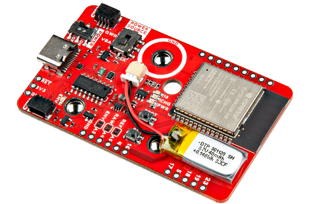
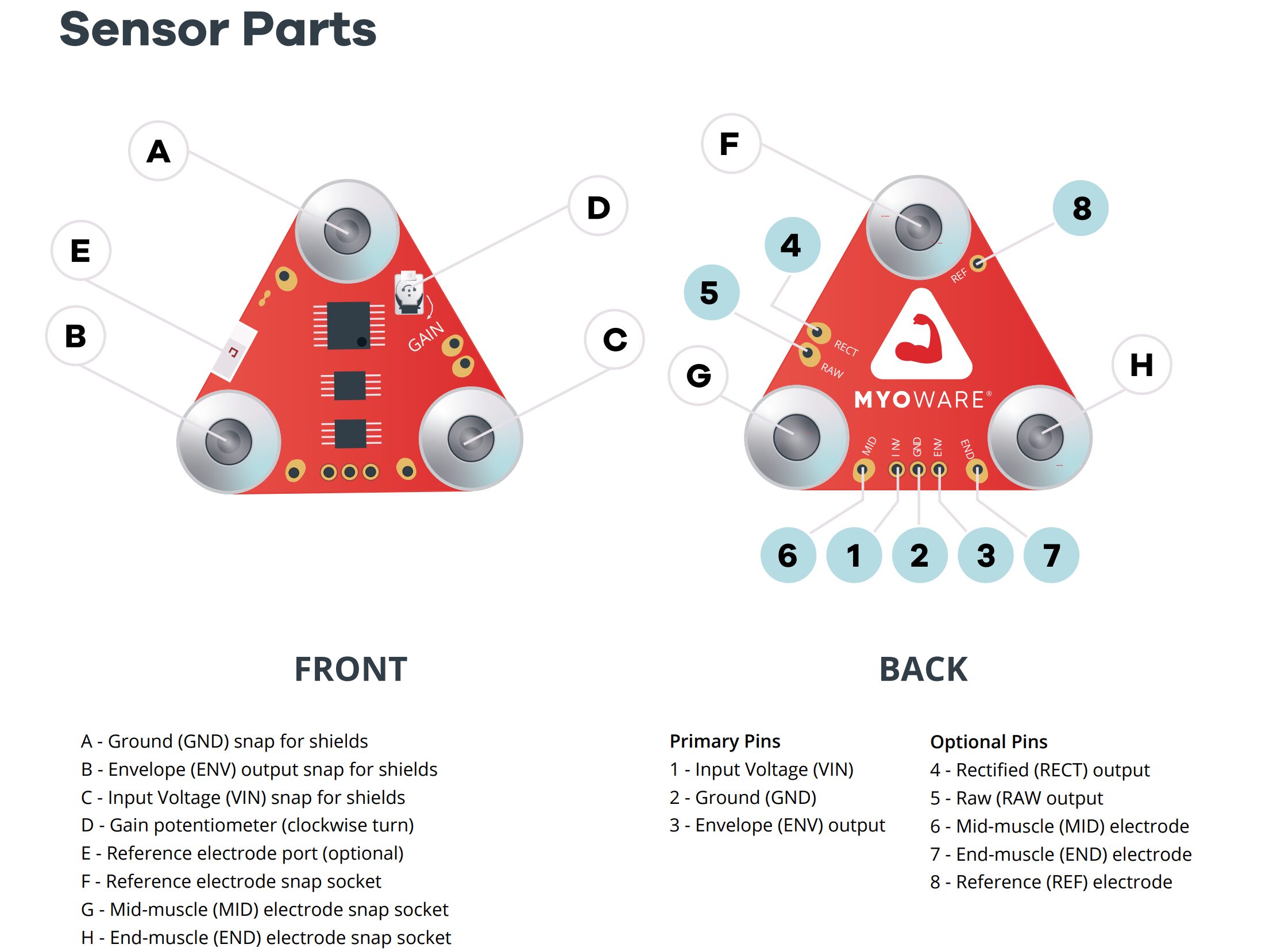
The SparkFun MyoWare 2.0 Wireless Shield can be called an accessory designed to work seamlessly with the MyoWare 2.0 Muscle Sensor. The module is built around an ESP32-WROOM module and houses a built-in 40mAh LiPo battery for wearable applications. Application includes Prosthetics and Assistive Devices, Educational Projects, Wearable, and Robotics.
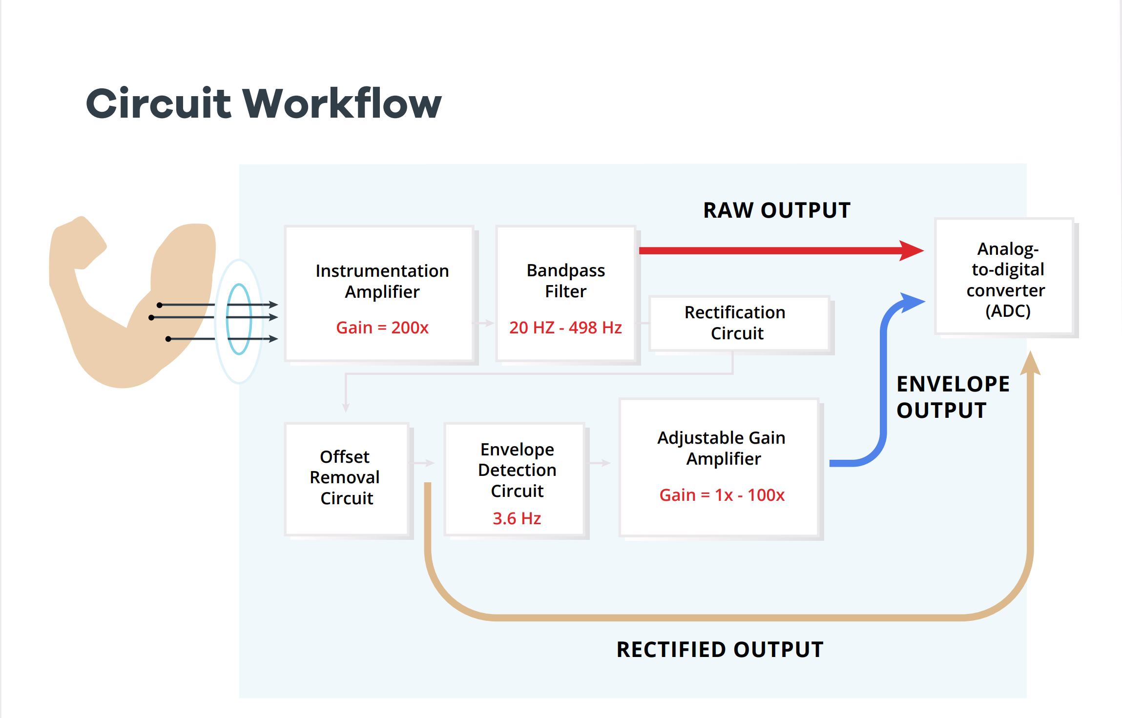
The MyoWare sensor measures muscle activity using surface electromyography (sEMG) by detecting the electrical potential of muscle fibers. When muscles flex, they activate more fibers, increasing electrical activity. The MyoWare converts this into an analog signal, where stronger contractions produce higher voltages.
MyoWare circuit workflow
The MyoWare sensor measures muscle activity using surface electromyography (sEMG), detecting the electrical potential when muscles flex and activate more fibers, thus increasing their electrical activity. It then translates this into an analog signal that directly corresponds to the muscle contraction’s intensity: stronger contractions yield higher output voltages.
As an interface, the board has a USB Type-C port, and on the PCB, there is a CH340 USB to UART converter for programming. Additionally, it features snap connectors for easy integration with the MyoWare 2.0 Muscle Sensor and offers Qwiic connectivity, status LEDs, protection circuits, a bootloader, and general-purpose buttons, making it suitable for educational and wearable tech projects.
SparkFun MyoWare Wireless Shield Specifications:
Processor & Core Features:
Espressif ESP32-WROOM Module: Central processing unit with robust performance for Wi-Fi and Bluetooth functionalities.
MCP73831 Single Cell LiPo Charge IC: Manages charging of the built-in LiPo battery with a charge rate set to ~40mA.
RT9080 Voltage Regulator: Provides stable 3.3V output from input voltages, ensuring reliable operation of the device and its components.
CH340 USB-to-Serial Converter: Facilitates communication between the microcontroller and a computer for programming and data transfer.
Power Management:
Input Voltage: 5V via USB Type-C Connector.
Output Voltage: 3.3V via voltage regulator and Qwiic Connector.
Built-in LiPo Battery: 40mAh capacity, 3.7V nominal voltage, with a max charge current of 1C (40mA).
Power Source Switches: For Power ON/OFF and selection between power sources.
Protection Components:
ESD Protection Diodes for USB Data Lines.
Ideal Diodes for protection on the VBATT and VUSB nets.
Resettable PTC Fuse rated at 6V/500mA.
Connectivity & Expansion:
2x Qwiic Connectors: For easy daisy-chaining of I2C devices without soldering.
General Purpose I/O: Including 3x female snap pins for power and EMG envelope output.
I2C Pull-Up Resistors: 2.2kΩ pull-up resistors for I2C communication.
Sensors & Indicators:
MyoWare® 2.0 Muscle Sensor Form Factor: For capturing muscle activity signals.
LEDs: PWR (Power), CHG (Charge Status), 13 (User), ENV (Envelope) for easy status indication.
Additional Features:
Jumpers: For custom configuration (PWR, SHLD, REF, RAW, ENV, I2C).
Buttons: For reset and general-purpose/bootloader actions.
Board Dimensions: 63.5mm x 38.0mm (2.50in. x 1.50in.), ensuring a compact form factor.
The MyoWare 2.0 Wireless Shield features a 40mAh LiPo battery, with a 40mA charge circuit powered by the onboard USB Type-C connector. Additionally, it offers Qwiic connectors and 2.2kΩ pull-up resistors for easy expansion, plus breakout pins for the ESP32 module. On top of that it has status LEDs and jumpers for enhanced user control and customization.
SparkFun provides comprehensive documentation for the MyoWare 2.0, including board dimensions, hookup guides, quickstart and advanced guides, patents, datasheets for the MCP73831 and the 40mAh LiPo battery, MSDS, the MyoWare Arduino library, and an ecosystem page for extended information and support.
The SparkFun MyoWare 2.0 Wireless Shield is available for $26.95 on SparkFun’s website, the Shield is not designed for medical diagnostics or treating diseases in humans or animals, as specified by the company.
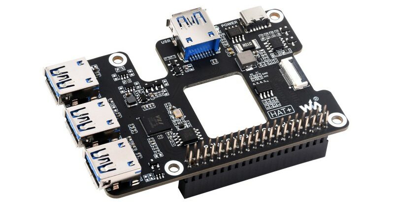
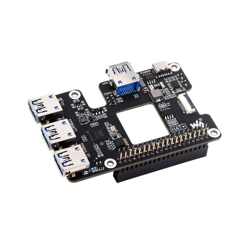
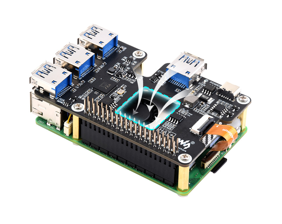
The Waveshare PCIe to USB HAT+ is designed to extend the capabilities of the Raspberry Pi 5 or the Rockchip Rock Pi boards by adding four more USB 3.2 high-speed USB ports.
The module will also feature real-time power status monitoring and allow USB power management through software. Additionally, the board has an EEPROM to store Pi IDs and other things and it features a vent to keep the Pi cool.
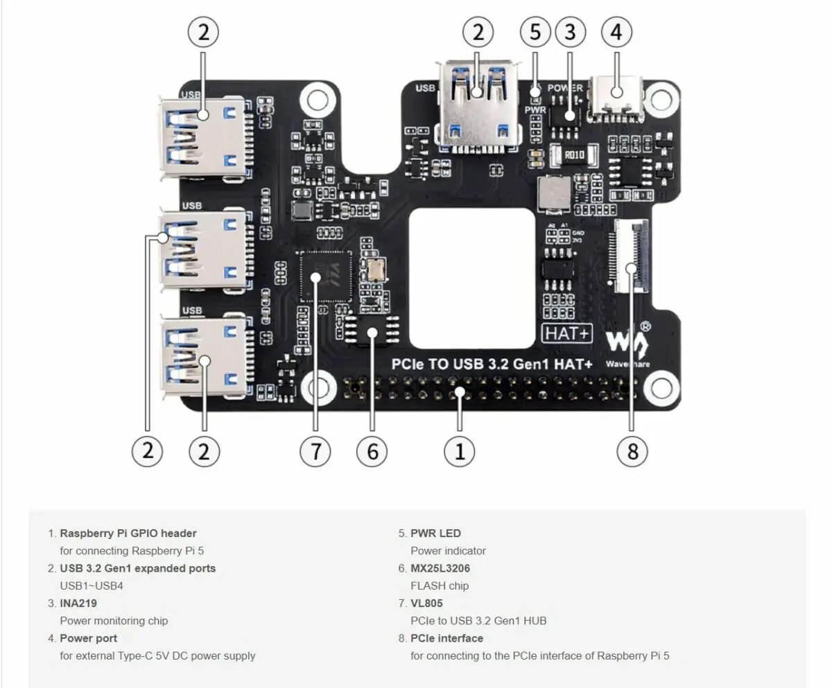
This device adds four USB 3.2 Gen1 ports to the Raspberry Pi 5, utilizing a VL805 PCIe to USB converter. It allows full access to the GPIO headers and monitors power through an INA219 chip, with external power supported via a Type-C port. It also includes a power indicator LED and an MX25L3206 flash chip, enhancing the Raspberry Pi 5’s capabilities. Waveshare states the device is ready to use out of the box and offers an installation guide and more on their wiki page. For GPIO control, soldering a 0R resistor is necessary, with instructions provided online.
Equipped with VL805 original high-performance main control chip
Reserved airflow vent for cooling fan to enable better cooling
Support USB power control
Dimension – 85 x 49mm
The company mentions the device’s plug-and-play nature and you don’t need extra software or hardware to run it properly. Installation and how-to guides are available on their Wiki Page. However, default GPIO control requires soldering a 0R resistor, with instructions also provided on the Wiki.
You can buy the PCIe to USB 3.2 HAT+ on Amazon for $27.99, or get it directly from the Waveshare store for $19.99, not including shipping costs.
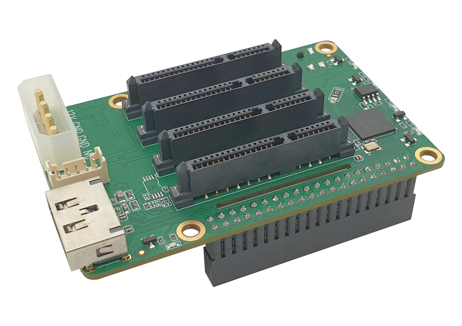
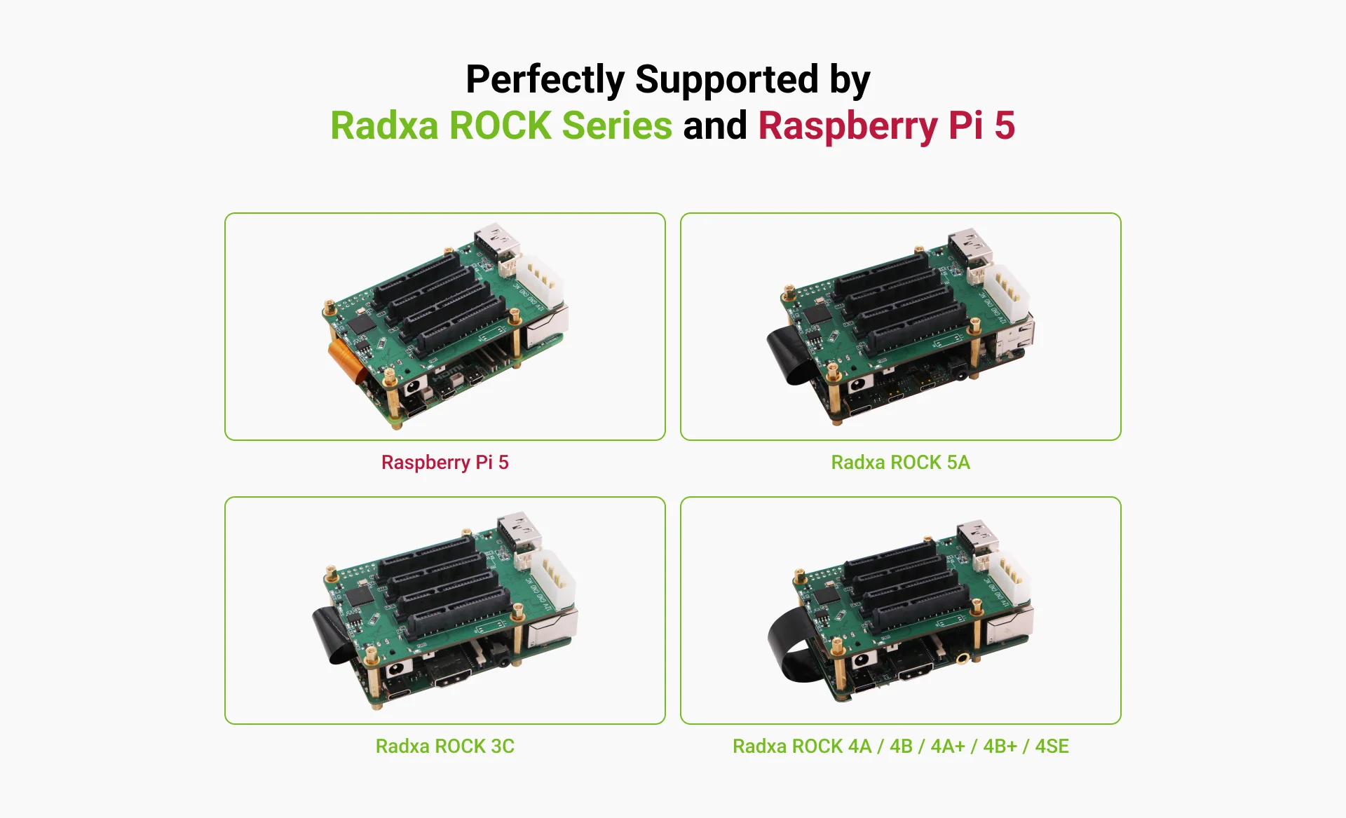
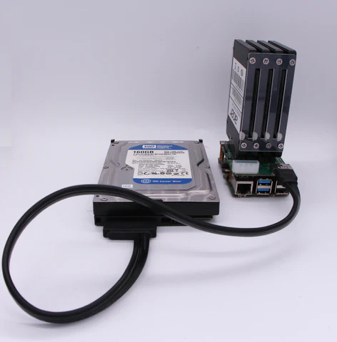
The Radxa Penta SATA HAT is a NAS board designed for RADXA’s Rock Pi and Raspberry Pi, enabling the connection of up to five HDD/SSD drives. This allows for the construction of powerful NAS systems with up to 100TB of storage.
The device supports up to five HDD/SSDs, four of which are connected to the top of the board, and the fifth is connected to an eSATA port at the front of the board. It can handle a total capacity of 100TB and supports RAID 0, 1, and 5 configurations. Additionally, it features HDD suspend mode, external standard ATX power supply support for 3.5-inch HDDs, an optional PWM control fan for HDD heat management, and an optional OLED display for IP/store information.
The Penta SATA HAT is compatible with both Rock Pi and Raspberry Pi 5, featuring an easy setup process detailed in Radxa’s guide. It utilizes a JMB585 controller across two PCIe 2.1 lanes to provide up to 10Gbps of bandwidth, enabling speeds of up to 803 MB/s with five SSDs configured in RAID 0.
Up to 100TB Storage: Supports 5 HDD/SSD drives for extensive storage options.
SATA & eSATA Ports: 4 internal SATA and 1 external eSATAp with power for flexible disk setups.
Fast Data Transfer: Utilizes PCIe 2.1 with 2 lanes for up to 10Gbps bandwidth.
Power Versatility: Supports DC and ATX power supplies, with special features for energy efficiency.
RAID & Cooling: Offers software RAID 0/1/5 and optional PWM fan for temperature control.
Display & Compatibility: Optional OLED for monitoring; compatible with Rock Pi 4, Rock 3, and Rock5 Model A.
High-Speed Performance: Achieves up to 803MB/s with SSDs in Raid0, powered by JMB585 chipset.
Inside the box, you will get the Penta SATA HAT board and the M.2 interface board with a high-speed Ribbon connector cable along with an eSATA cable. The Penta SATA HAT can be purchased from AllNetChina for $49.00, and it’s also available at a slightly lower price of $44.99 through Arace Tech’s online store.
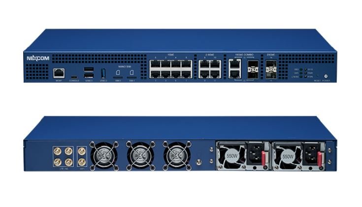
The NEXCOM TCA 6710 is a 1U rackmount PC/server/AI Edge computer thingy, also referred to as an accessory, powered by the Marvell OCTEON 10 COM-HPC module. It features an 8-core 2.5GHz Armv9 Neoverse N2 processor with 25GbE ports for enhanced computing. Designed for scalable solutions, it offers significant improvements in bandwidth and performance needs.
The TCA 6710 offers adaptability and high performance with support for the latest DDR5 memory and PCIe Gen5. Its design, based on the COM Express module, allows for easy upgrades tailored to your workload. The device provides a wide range of Ethernet options from 1GbE to 25GbE, along with wireless communications capabilities including Wi-Fi and LTE/5G, making it ideal for IoT, AI, and network security applications.
The TCA 6710 allows users to choose from different carrier boards, each made for specific requirements. This modular design simplifies software development and saves costs, making it a versatile choice for various applications.
NEXCOM TCA 6710 Specifications:
SoC/CPU:
Marvell OCTEON 10 CN10308: 8-core Armv9, 2.5GHz.
Memory & Storage:
DDR5-4800 ECC SO-DIMM slot (up to 32GB)
32GB TLC eMMC storage
Dual 512MB SPI Flash modules
Connectivity Options:
Two 25GbE SFP28 ports
Dual 10GbE RJ45/SFP+ combo ports
Four 2.5GbE RJ45 ports
Eight 1GbE RJ45 ports
RJ45 management port for RunBMC
Expansion Capabilities:
M.2 Key M socket (2232/2242/2260/2280/22110) for PCIe Gen5 x4
Two NANO SIM slots for cellular connectivity
Mini-PCIe socket for Wi-Fi (PCIe Gen3 x1)
M.2 Key B socket (3042/3052) for LTE/5G modules (USB signal)
I/O Interfaces:
Two RP-SMA connectors for Wi-Fi antennas (2.4/5/6GHz)
Four SMA connectors for LTE/5G antennas
Six indicator LEDs for system status, power, fan, SSD, Wi-Fi, and LTE/5G
Power and reset buttons
Additional Features:
Socket for NEXCOM TPM 2.0 module
USB Ports:
USB3.2 Gen1 Host (Type-A)
Two USB2.0 Host ports (Type A)
USB Console port (Type C)
Power Supply:
550W 1+1 CRPS redundant power
Operating Conditions:
Operating temperature range: 0℃ to 45℃
Physical Dimensions:
Chassis size: 430 x 299.8 x 44mm
The company has yet to reveal the pricing for this product. For more details, including specifications and availability, please refer to the official product page and the announcement page.