Piunora Carrier Board For Raspberry Pi Compute Module 4

Piunora Carrier Board

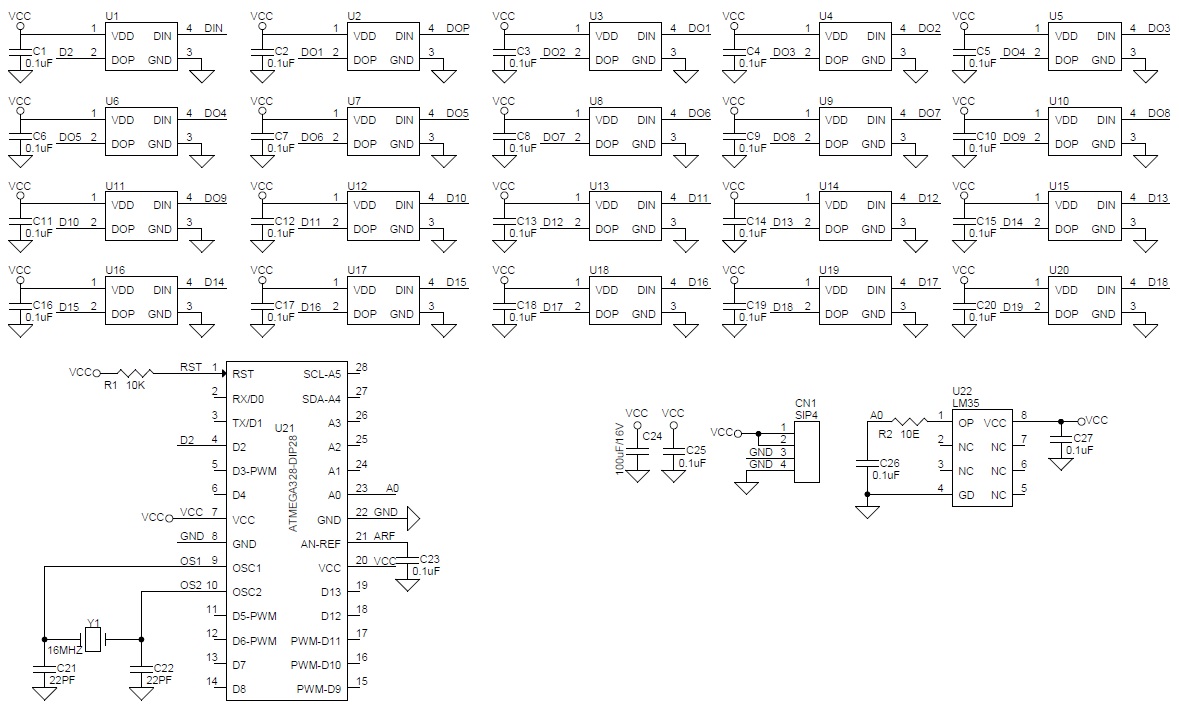
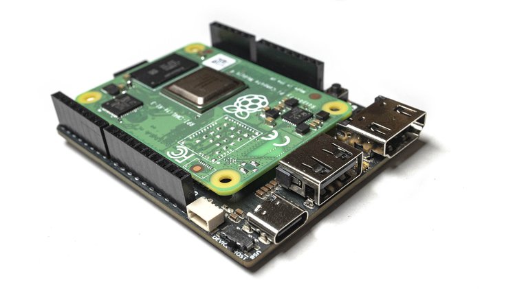
Piunora carrier board for Raspberry Pi CM4 is designed for rapid electronics prototyping in a Linux environment. The official carrier board of the Raspberry Pi CM4 is large as it covers all features required. Whereas, the Piunora carrier board comes with similar functionalities but with a smaller form factor similar to Arduino Uno or Adafruit Metro. It also features GPIO, HDMI, USB, and power connections from the Broadcom BCM2711 SoC as the PCle interface.

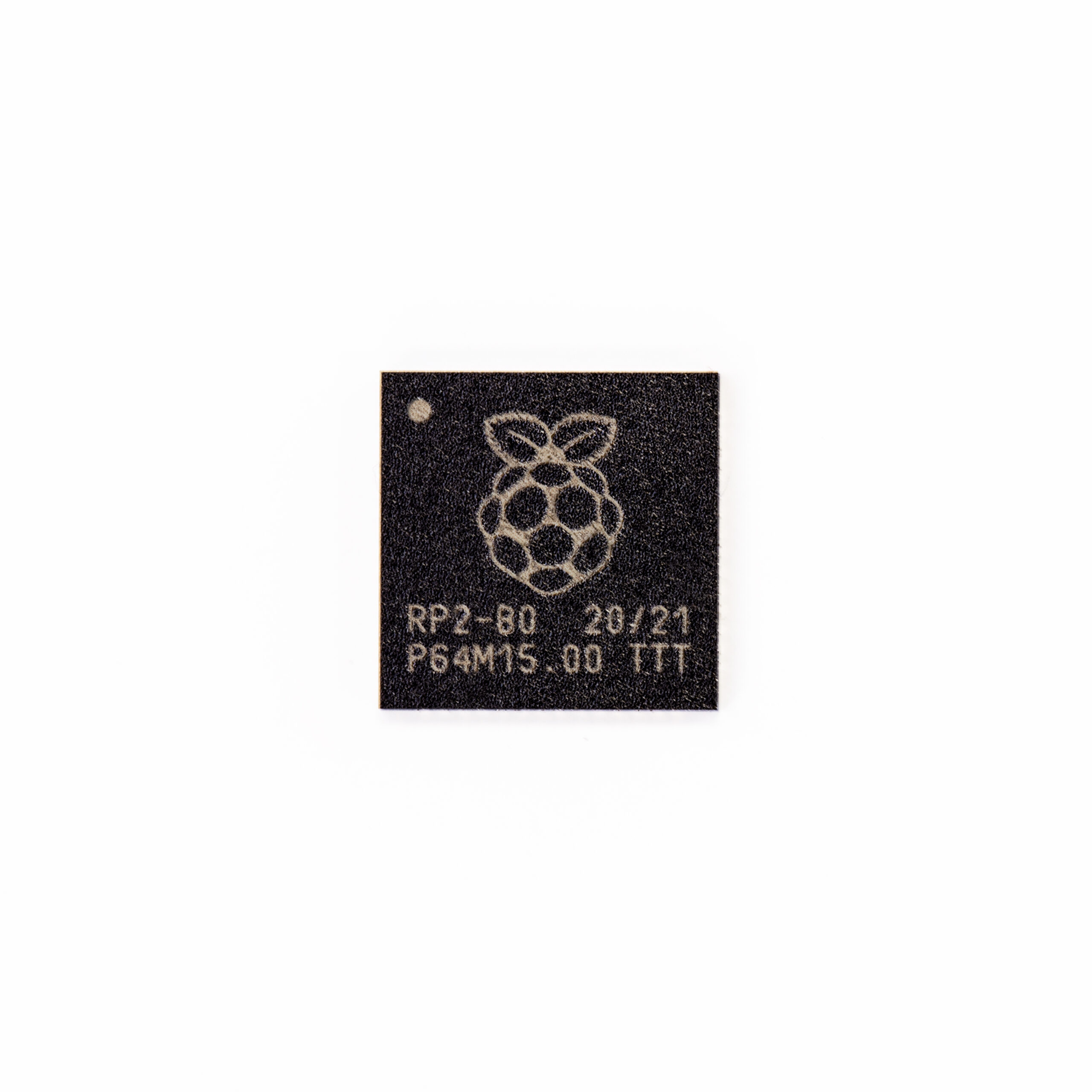
Timon’s Piunora carrier board has SoM compatibility for specific functionalities with a quad-core Cortex-A72 processor working at a frequency of 1.5 GHz. It offers RAM from 1GB to 8GB with an optional 4GB to 32GB eMMC flash memory. The carrier board comes with an optional wireless module with 802.11b/g/n/ac WiFi 5 and Bluetooth 5.0.

It has a MicroSD card socket for the operating system while working on Raspberry Pi CM4Lite as an SoM. The HDMI 2.0 port comes with a 4Kp60 feature for real-time video output. The camera interfaces with a MIPI connector to a USB 2.0 port or USB-C port with support for data and power using a host switch.

Backside of Piunora Carrier Board

Key Features

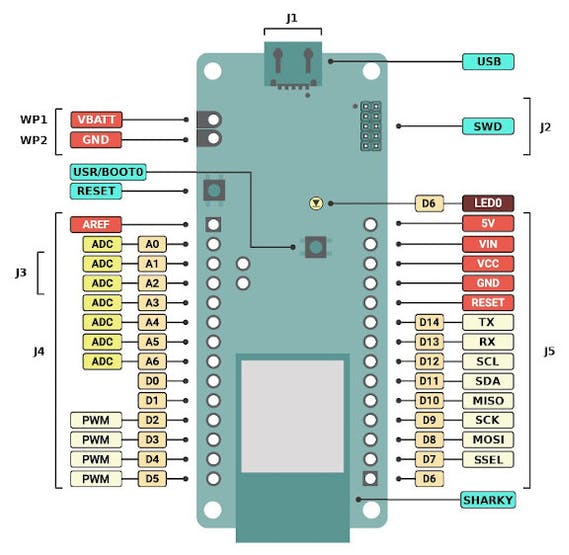
  • Arduino UNO R3 / Adafruit Metro compatible form factor (3.3 v logic)
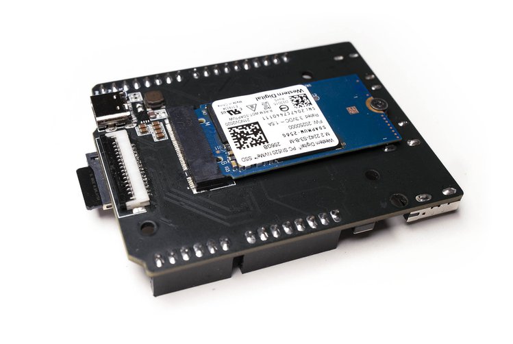
  • PCI-e through M.2 B-Key connector on the rear of the board
  • On-the-fly switching between USB host (USB Type-A) and device mode (USB Type-C)
  • A full-sized camera connector that supports all Pi-compatible cameras
  • 6x ADC Inputs (10 bits / 200k/s)
  • Full-sized HDMI port supporting high bandwidth of data
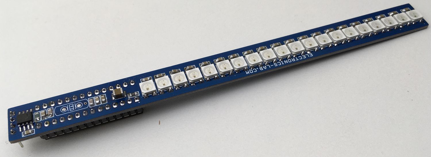
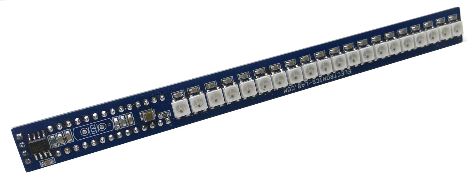
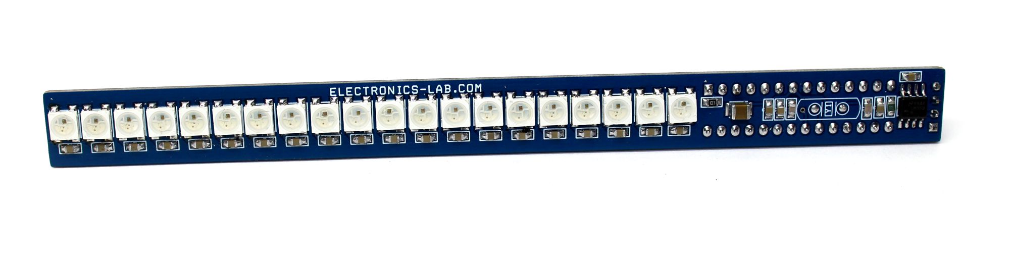
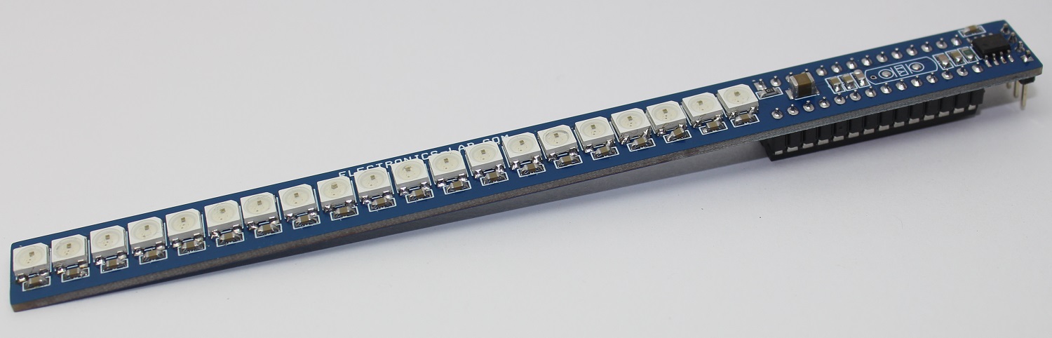
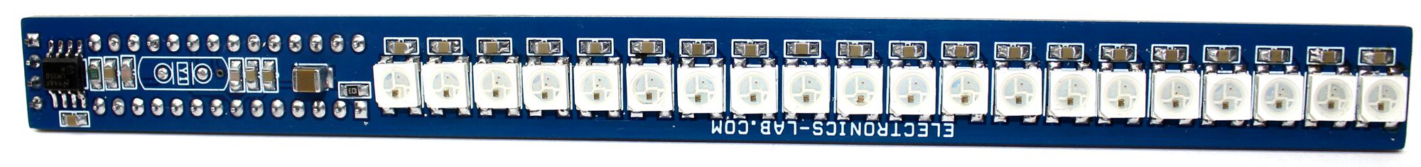
  • WS2812 Smart RGB LED for user status
  • One user-controllable button
  • CircuitPython compatibility with ease of programming by a plugin to computer

The official Raspberry Pi compute module provides more I/O ports than the normal Raspberry Pi additionally, it has the feature of designing hardware customized user-specific applications, rather than having general-purpose functionalities. But, an interface is needed for its functioning as the normal I/O ports are not available on the official Raspberry Pi CM4. Hence, the Pinuora carrier board designed by Timon solves the problem of prototyping.

The Piunora carrier board allows some additional features that are complex to implement using the official Raspberry Pi 4, like running the Pi as a USB gadget rather than as a host component. Hence, it simplifies certain types of development and allows quick implementation. This USB gadget mode functions through a virtual Ethernet connection or as a USB storage device. Adafruit Blinka a compatibility layer for CircuitPython on Linux SBCs allows the usage of the Piunora carrier board similar to any other CircuitPython dev board.

Timon’s Latest Tweet

The board features flexible connectivity with an Arduino-compatible header for various interfaces. This includes 6x ADC, digital I/Os, I2C, SPI, and UART. It also comes with a Stemma QT connector and an M.2 B-key socket for further expansion of the device.

There is no information about the price for the Piunora carrier board at this point in time. However, Timon’s latest tweet on 15 January 2021 says:

“Now up on Crowd Supply. No ETA yet when the campaign will start but be sure to sign-up to be notified.”

For more information visit the Crowd Supply’s product page for Piunora Carrier Board. The images and technical specifications have also been taken from the product page.

STM32WB5MMG Wireless Module supports Bluetooth LE, Zigbee, OpenThread, and More

STMicroelectronics has introduced their first STM32-based wireless module designed to accelerate the market introduction of new Bluetooth® LE and 802.15.4 based IoT devices: the STM32WB5MMG.

The compact and ultra-low-power STM32WB5MMG is:

“a complete ready-to-use subsystem in a single package; the STM32WB5MMG assures excellent radio performance out of the box and comes as a certified solution according to Bluetooth, Zigbee, and OpenThread specifications.”

said the company’s Group Vice President, Microcontroller Division.

The STM32-based module aims to reduce design complexities like tuning the antenna and optimizing the RF, thus allowing quicker implementation into customer designs. It has a good receiver sensitivity and a high output power that guarantees a best-in-class RF performance, and also supports BLE 5.0, Zigbee 3.0, OpenThread, 802.15.4 proprietary protocols and even static and dynamic concurrent modes.

Features and Specifications of the STM32WB5MMG wireless module include:

  • Arm® Cortex®-M4 CPU with FPU and ART; up to 64 MHz speed
  • Arm® Cortex®-M0+ for radio and security tasks; up to 32MHz speed
  • 1 Mbyte Flash memory
  • 256 Kbyte SRAM
  • Supports 2 Mbits/s
  • Fully integrated BOM, including 32 MHz radio and 32 kHz RTC crystals
  • Integrated SMPS
  • Two layers PCB compatible, using external raw pins only.
  • Up to 68x GPIOs
  • 2x ULP Comparators
  • Integrated IPD for reliable antenna matching
  • Ultra-low-power modes for battery longevity
  • Two watchdog timers
  • Integrated chip antenna
  • Bluetooth® Low Energy 5.0, Zigbee® 3.0, OpenThread certified
  • Dynamic and static concurrent modes
  • IEEE 802.15.4-2011 MAC PHY
  • 1.8 V to 3.6 V VDD range
  • TX output power: Up to +6 dBm
  • RX sensitivity: -96 dBm (Bluetooth® Low Energy at 1 Mbps), -100 dBm (802.15.4)
  • Range: Up to 75 meters
  • Security features: Secure firmware installation (SFI) for radio stack, Customer key storage/key management services, PKA, AES 256-bit, TRNG, PCROP, CRC, 96-bit UID, possibility to derive 802.15.4 and Bluetooth® Low Energy 48-bit UEI
  • Dimensions: 7 mm x 11.3 mm
  • Temperature Range: -40 ºC to 85 ºC
  • Certifications: CE, FCC, IC, JRF, SRRC, RoHS, GOST, KC, NCC, REACH

The STM32WB5MMG is suitable for a number of applications like home automation, smart locks, wireless audio devices, and healthcare personal trackers. Its ultra-low-power feature means an “extended battery lifetime, small coin-cell batteries or energy harvesting.”

The wireless module is expected to be a solution to common cost and design complexities, so the company is also making plans for an STM32WB55MMG-DK board which will include an external memory, LCD, sensors, and more features that will help developers explore all the functionalities of the module.

Video

The STM32WB5MMG wireless module is currently selling at $5.66 for orders of 10,000.

More details are available on the official product page and the Blog.

GRA115Q 3U VPX GPU Board for Intensive RADAR and AI Applications

GRA115Q GPU Board

The GRA115Q 3U VPX is a GPU board for applications like radar and video analysis. It is a good option for systems that require high-performance graphical computations with compatible advanced GPUs. The General Purpose GPU board is based on NVIDIA Turing architecture that comes with dedicated tensor cores for accelerating deep learning inferences. Hence, it could be a good fit for use cases in situational awareness and moving map applications

GRA115Q GPU board comes with two options for GPUs; NVIDIA Quadro RTX 5000 or Quadro RTX 3000 GPU that have 4 times increased performance efficiency over the NVIDIA Pascal class GPUs. The Quadro RTX5000 offers up to 9.49 TFLOPS of single-precision floating-point compute performance. It can also accelerate up to 448 GB/s memory bandwidth with its 256-bit 16 GB GDDR6 graphics memory for high-intensity data applications.

Output Configurations For GRA115Q GPU Board

  • Dual Display Port 1.4a + Dual SL-DVI outputs 2x DisplayPort 1.4a, 2x SL-DVI at 1920 x 1200 both working up to 60Hz.
  • Quad SL-DVI outputs have 4x SL-DVI at 1920 x 1200 works at 60Hz outputs.
  • Quad DisplayPort 1.4a at 4K functions up to a frequency of 60Hz.

The SL-DVI outputs are compatible with the GRA112D, GRA113D, GRA112Q, GRA113Q, and the GR5 3U VPX graphics boards. GRA115Q GPU board has a flexible range of operating system support including CUDA, Linux, NVIDIA CUDA, OpenCL, OpenGL, Windows 7, and Windows 10. It features a DVI (Digital Visual Interface) video output for connection to a display device and controllers. It also has an embedded PCle interface for connecting additional peripheral components.

Block Diagram

Block Diagram of GRA115Q GPU Board

Vice President of Product Management at Abaco Systems says:

“The GRA115Q provides a portfolio of quick solutions for mission-ready systems of all sizes and processing requirements. It is dedicated to being at the forefront of GPU technology. GPU and GPGPU functions are an important part of the ethos and capability of the mission-ready system.”

GRA115Q GPU board supports AXIS ImageFlex, which is an image processing and visualization toolkit. Hence, it allows quick implementation of advanced image processing and visualization applications aimed at the size, weight, and power (SWaP) sensitive platforms. It is for intensive graphical computations and GPU processing. It is compatible with dynamic programming frameworks including OpenGL, OpenCL, CUDA, and OpenCV.

The extended temperature range for the device is from -40° to +85°C. The GRA115Q GPU board has a rugged conduction-cooled architecture along with air cooling. Hence, it stabilizes the heat generated due to intensive graphical processing in the device. The board has a protective layer of thin polymeric conformal coating.

There is no information about the pricing and availability on the product page at this point in time. For more information visit the official product page. Images and technical specifications have also been taken from the product page.

Raspberry Pi moves into the microcontroller market with RP2040 MCU

Raspberry Pi Pico

We are very excited to introduce the all new Raspberry Pi Pico, a tiny, $4, MicroPython and C/C++ board with custom RP2040 silicon. This is the first product from the Raspberry Pi Foundation built with their in house designed RP2040. At $4 and available individually or even available on reels, this Raspberry Pi is the next step in home and industrial products. Looking at the edge of the PCB you can see the Raspberry Pi Pico has been designed to be used with header pins or soldered directly onto your products PCB.

James Adams, Chief Operating Officer, Raspberry Pi Trading, said:

“This is the start of an exciting new era for Raspberry Pi. With Raspberry Pi Pico, and RP2040, we have been able to draw on insights drawn from a decade of using other vendors’ microcontrollers, and to create an innovative silicon platform for our customers. People have used Raspberry Pi to create a broader spread of projects and products than we could have imagined a decade ago; we’re sure the same will be true of Raspberry Pi Pico.”

Front and Back photos

Raspberry Pi Pico Specifications:

  • GPIO and Debug Pins
  • RP2040 Microcontroller
  • Two cores clocked at 133MHz
  • 256KB RAM
  • 2MB of On-boars QSPI Flash Memory
  • Micro-USB B Port for Power, Data and Reprogramming of the Flash memory.

Raspberry Pi Pico Peripherals:

  • I2C x4
  • SPI x2
  • PWM x2
  • UART x2
  • Timer
  • RTC
  • ADC & TS

Raspberry Pi Pico Dimensions: 21mm (W) x 51.3mm (L) x 3.9mm (H)

Raspberry Pi Pico GPIO Pinout

The 40 pin 21×51 ‘DIP’ style 1mm thick PCB with 0.1″ through-hole pins also with edge castellations

  • Exposes 26 multi-function 3.3V General Purpose I/O (GPIO)
  • 23 GPIO are digital-only and 3 are ADC capable
  • Can be surface mounted as a module
  • 3-pin ARM Serial Wire Debug (SWD) port

First Product built on Raspberry Pi designed Silicon – Meet the RP2040

Raspberry Pi Pico is built around the brand-new Raspberry Pi RP2040 microcontroller, delivering a flexible, highly affordable development platform that can also be directly deployed into end products, reducing time-to-market. RP2040 offers high performance for integer workloads, a large on-chip memory, and a wide range of I/O options, making it a flexible solution for a wide range of microcontroller applications. Professional design engineers who are already comfortable working with Raspberry Pi will easily adopt the Raspberry Pi Pico and appreciate its ease of use and affordability.

RP2040 Microcontroller


RP2040 is a low-cost, high-performance microcontroller device with flexible digital interfaces. Key features:

  • Dual Cortex M0+ processors, up to 133 MHz
  • 264 kB of embedded SRAM in 6 banks
  • 30 multifunction GPIO
  • 6 dedicated IO for SPI Flash (supporting XIP)
  • Dedicated hardware for commonly used peripherals
  • Programmable IO for extended peripheral support
  • 4 channel ADC with internal temperature sensor, 0.5 MSa/s, 12 bit conversion
  • USB 1.1 Host/Device

Developer tools
Simple drag and drop programming via micro-USB. 3-pin Serial Wire Debug (SWD) for interactive debugging. Comprehensive C SDK, mature MicroPython port, and extensive examples and documentation.

Power
On-board power supply to generate 3.3V for RP2040 and external circuitry. Wide input voltage range, from 1.8V to 5.5V, giving designers the flexibility to select their preferred power source.

Temperature Controlled RGB LED Light Stick – Mood Light

The circuit presented here is a LED light stick which changes its color in respect with the room temperature. This is an Arduino compatible open source project consisting of 20 x WS2812B Addressable RGB LEDs, LM35 Temperature Sensor and ATmega328 microcontroller. Atmega328 microcontroller reads the LM35 temperature sensor and changes the RGB LEDs color as per sensor analog output. Multiple units of this board can be installed in the room to create full light color effects. Colors of this light will change as the atmosphere’s temperature changes. Placing the LED stick underneath a furniture or behind picture frames on the wall helps create a nice effect as well as improve the ambience of the room.

Features

  • Operating Supply 5V DC
  • Current Consumption 200mA (When all LEDs on)
  • 20 x WS2812 RGB Addressable LEDs
  • On Board LM35 Temperature Sensor
  • PCB dimensions: 159.86 x 13.81 mm

Arduino I/O Configuration (ATmega328 Chip)

  • WS2812 LEDs connected to Digital Pin D2
  • Temperature Sensor LM35 Connected to ADC Analog pin A0

Programing

Example Arduino Code is provided to test the board and the code and can be modified or re-written as per user requirements.

Read the following tutorial about Atmega328 microcontroller Programming using Arduino IDE: https://www.arduino.cc/en/Tutorial/BuiltInExamples/ArduinoToBreadboard

WS2812B LED

WS2812B is an intelligent control LED light source that the control circuit and RGB chip are integrated in a package of 5050 components. It internal include intelligent digital port data latch and signal reshaping amplification drive circuit. Also include a precision internal oscillator and a voltage programmable constant current control part, effectively ensuring the pixel point light color height consistent. The data transfer protocol uses single NZR communication mode. After the pixel power-on reset, the DIN port receive data from controller, the first pixel collects initial 24bit data then sent to the internal data latch, the other data which reshaping by the internal signal reshaping amplification circuit sent to the next cascade pixel through the DO port. After transmission for each pixel, the signal to reduce 24bit. pixel adopt auto reshaping transmit technology, making the pixel cascade number is not limited the signal transmission, only depend on the speed of signal transmission. RESET time>280μs, it won’t cause wrong reset while interruption, it supports the lower frequency and inexpensive MCU. Refresh Frequency updates to 2KHz, Low Frame Frequency and No Flicker appear in HD Video Camera, it improves excellent display effect. LED with low driving voltage, environmental protection and energy saving, high brightness, scattering angle is large, good consistency, low power, long life and other advantages. The control chip integrated in LED above becoming more simple circuit, small volume, convenient installation.

Schematic

Parts List

SR.QNTYREF.DESCVENDOR/DIGIKEY/MOUSER
11CN14 PIN MALE HEADER 2.54MM PITCHDIGIKEY S1011EC-40-ND
224C1 TO C20,C23,C25,C26,C270.1uF/50V SMD SIZE 0805YAGEO
32C21,C2222PF 50V SMD SIZE 0805YAGEO
41C24100uF/16V SDM SIZE 1210YAGEO
51R110K 5% SMD 0805YAGEO
61R210E 5% SMD SIZE 0805YAGEO
720U1 TO U20WS2812B LED 5050DIGIKEY 1528-1104-ND
81U21ATMEGA328-DIP28DIGIKEY ATMEGA328P-PU-ND
91U22LM35 SMD SOIC8DIGIKEY LM35DMX/NOPBCT-ND
101Y116MHZDIGIKEY X1103-ND

Connections

Gerber View

Photos

Video

WS2812B Datasheet

DBM10 – Low-power Edge Ml/AI SoC with DSP and Neural Network Engine

DSP Group, a leading global provider of wireless and voice-processing chipset solutions has introduced a low-power AI/ML-enabled dual-core SoC called DBM10.

According to the CEO of the company, almost all edge applications for AI require the ultimate as regards low power, small form factor, cost effectiveness, and fast time-to-market. So it’s with great enthusiasm that they bring DBM10 to the desk of their customers and partners.

“Our team has worked to make the absolute best use of available processing power and memory for low-power AI and ML at the edge—including developing our own patent-pending weight compression scheme—while also emphasizing ease of deployment. We look forward to seeing how creatively developers apply the DBM10 platform.”

DBM10 AI SoC is a high-performance and low power chip with Digital Signal Processor and dedicated nNetLite Neural Network Engine. It is designed to improve voice and sensor processing and also ensure that consumption is low when working with sufficient-sized neural networks.

DBM10 is supported by an embedded memory along with serial and audio interfaces that make it easily compatible with many external devices, including  application processor, codecs, microphones, and sensors. It is well suited for wearables, tablets, smartphones, true wireless stereo headsets and smart home gadgets like remote controls.

Features of the DBM10 AI SoC include:

  • SPI and I2C serial interfaces
  • Universal Asynchronous Receiver Transmitter for serial communication
  • PDM and TDM audio interfaces
  • General Purpose IOs for MCUs and peripherals
  • 32-bit timer
  • Watchdog timer
  • Low-power ADCs for analog microphones
  • JTAG for debugging, and,
  • 48-pin Quad Flat No-leads package, and,
  • Suitable for AI voice-based applications.

Specifications of the neural network processor:

  • Has a compact form factor of about 4 mm x 4 mm
  • Has ~ 500 µW ultra-low-power inference consumption for voice NN algorithms
  • can run “Hello Edge 30-word detection” model @ 1 MHz (125 MHz available)
  • allows porting of large models, typical about 10s of megabytes, without significant accuracy loss using model optimization and compression.

The SoC offers “full flexibility of partitioning innovative algorithms between DSP and NN processor”, and allows machine learning, voice and sensing functions such as noise reduction, voice trigger, voice authentication, acoustic echo cancellation, wake-word detection, voice activity detection, and sensor data processing.

The SoC also offers a real-time software framework that has an internal host for communication with an external master processor running on Linux OS. The framework supports RTOS and provides drivers for processor peripherals and Android/Linux interface.

We don’t have any information on price, availability and shipment yet, but other relevant details about the SoC can be found either in the company’s press release page or the product page.

PD Micro – Breadboard-Friendly USB-C Power Supply Based on Arduino

We have all been there. Everytime we start adding new peripherals, sensors and actuators to our projects, we eventually will reach a point where the 3.3 and 5 V voltages from the microcontroller (when they are available) are not enough, either because we require more current than what the MCU pins can deliver, or we have different voltage requirements. A good example of this are motors and high power LED’s. But, if a microcontroller can’t deliver, then something else will. But what if the solution was already there, with your MCU and enabled you to have greater control over these voltages? Well, with the help of some USB Type-C magic and the new Arduino MCUs, you can!

The PD Micro is an innocent-looking Arduino at first, friendly enough for you to place it into a breadboard and start tinkering. But when you get to the nitty-gritty, you are going to find much more, something rather unique on this type of board. Through the use of a 30 V P-channel  MOSFET load switch controlled by an Arduino MCU and a library developed by Ryan Ma, you can safely enjoy USB Type-C’s promising USB PD (Power Delivery), which allows you to negotiate power of up to 100 W. The PD Micro adds some extra protection to your circuitry by only delivering the power required is ready and meets the target voltage and current levels. A really cool thing about it is that you can get away with not using another board. As you have already an Arduino at your disposal, all you might need for your project is already there.

Regarding specifications, you have at your disposal:

  • ATmega32U4 MCU, clocked at 16 MHz (Arduino Pro Micro)
  • I / O: 9x 10-bit ADC pins, 12x Digital I / O’s, 5x GND pins, 3x VBUS pins (USB Power Delivery) and 1x 5V pin
  • Power: USB PD grants negotiable 5 V, 9 V, 12 V, 15 V or 20 V at a maximum of 5 A (100 W at 20 V)
  • PD status LED’s: Tx / Rx activity, 5x for Power Delivery voltage level and 5x for current level
  • DC-DC converter for efficient 5 V 0.5 A output
  • Size: 1.6 x 0.7 inches (plus 0.3 inches for the power connector pins)
Pinout of the PD Micro

When it comes to the control of USB Power Delivery, this device has the unique feature of allowing you to control it with an Arduino. There are other boards that do this job, but I doubt you will find something nearly as convenient to use and with all the functionalities this one has. Lastly, this is still a CrowdSupply project, which already smashed its goal, while there are still some days left. You can get the cheapest kit, consisting of a PD Micro and the necessary headers and terminals for it at $28, with free US shipping.

PD Micro CrowdSupply link: https://www.crowdsupply.com/ryan-ma/pd-micro

Ambarella CV5 AI Vision SoC for Low Power Computer Vision Applications

CV5 AI Vision SoC

Ambarella announced the CV5 AI Vision SoC for AI applications using its specialized computer vision technology. The AI Vision SoC features 8K video or 4K video processing along with video encoding/decoding, and CVflow computer vision processing in a single, low-power design. The SoC is fabricated using 5nm technology and allows the development of intelligent automotive camera systems, consumer cameras (drone, action, and 360°), and robotic cameras.

Talking about its low power design, the SoC can function below 2W for 8K video recording at 30 fps, and below 5W for 8K video recording at 60 fps. The CVflow architecture of the device offers the DNN (Deep Neural Network) processing hence, compatible for intelligent cameras in numerous AI applications.

The target applications of the SoC include sports and robotics cameras. It also offers advanced image processing for VR cameras. It supports multi-channel drive recorders and data loggers. The SoC is expected to grow in the automobile industry for ADAS systems with multiple cameras for driver assistance. This includes lane departure warning, forward collision warning, and driver monitoring.

Key Features of CV5 AI Vision Processor

  • High-Efficiency Video Encoding with H.265 and H.264 video compression
  • Flexible multi-streaming capability and 8KP60 video performance
  • Multiple CBR and VBR bit rate control modes for encoding
  • CNN / DNN-based processing for detection and classification
  • Computer Vision engine for conventional CV operations
  • CNN toolkit for easy porting of neural networks implemented in Caffe, TensorFlow, PyTorch, or ONNX frameworks
  • Advanced image processing includes multi-exposure HDR and EIS
  • LED flicker mitigation and 3D motion-compensated temporal filtering (MCTF)
  • RGGB / RCCB / RCCC / RGB-IR / monochrome sensor support

Block Diagram of CV5 AI Vision SoC

The image signal processor (ISP) of the SoC can perform imaging in low-light conditions. Also, the high dynamic range (HDR) processing functions for optimized withdrawal of image details in high contrast conditions. “The CV5’s CVflow architecture provides computer vision processing at full 8K, enabling image recognition over long distances, with high accuracy.”

“The SoC also combines Ambarella’s powerful CVflow AI engine with dual Arm A76 CPUs to provide the performance necessary for a wide range of AI-based algorithms. CV5’s CVflow AI engine can accelerate simultaneous localization and mapping (SLAM), path planning, and obstacle detection, and avoidance algorithms for navigation and autonomous operation.”

For using customized neural networks for dedicated use cases there on the CV5 AI Vision SoC, Ambarella’s software development kit offers a complete set of tools for software and AI implementation. This development kit is also compatible with the company’s previous version CV28M SoC. The software ecosystem includes a compiler, debugger, and support for various ML frameworks, such as PyTorch, ONNX, Caffe, and TensorFlow.

For more information visit the official company page. Currently, the pricing information of the SoC is not available. Images and technical specifications have also been taken from the company page and announcement.

MKR SharkyPro Boards Packs STMicroelectronics’ STM32WB55CG into an Arduino MKR Form Factor

In the midst of discovering wireless modules that simplify Bluetooth LE, Zigbee, OpenThread connectivity, it turned out that Midatronics also has a SharkyPro module based on STM32WB55, and they have launched a pair of Arduino MKR form factor development boards called MKR SharkyPro I & II.

The Sharky MKR boards are built around the SharkyPro module that has STMicroelectronics’ STM32WB55CG/CE MCU with a 64 MHz Arm® Cortex®-M4 core serving as the application processor and a 32 MHz Arm® Cortex®-M0+ core as the network processor. They are also Bluetooth 5.0-certified with support for Mesh 1.0 software, proprietary BLE stacks, OpenThread software, and other IEEE 802.15.4 proprietary stacks like ZigBee ® , or proprietary protocols.

Key Features and Specifications SharkyPro I & II include:

  • SharkyPro Wireless Modules
    • STMicro STM32WB55CG/CE wireless MCU with an Arm Cortex-M4 core @ 64 MHz and an Arm Cortex-M0+ core @ 32 MHz; 512KB flash; 256KB SRAM
    • 2.4 GHz – RF transceiver
    • Bluetooth 5.0 Low Energy, Bluetooth Mesh 1.0, OpenThread, Zigbee, General IEEE 802.15.4 protocol stacks
    • Onboard chip antenna (for SharkyPro I)
    • SMA antenna connector (for SharkyPro II)
    • 3.3V supply voltage
    • 13 nA consumption in shutdown mode
    • 600 nA consumption in Standby mode + RTC + 32 KB RAM
    • Operating temperature: -40 °C to 85 °C
    • RX Sensitivity: -96 dBm
    • Dimensions: 23 mm x 14.6 mm
  • 1x Micro USB port for power and programming
  • 2x 14-pin headers compatible with Arduino MKR pinout and featuring USART, ADC, SPI, I2C, QSPI
  • 1x 8-pin SWD connector
  • 1x Reset button
  • 1x User-programmable input button
  • User LED
  • Power Supply: 5V via Micro USB port, 2.5 to 5.5V via Vin pin, 2.0 to 5V via Vbatt pin (battery)
  • Dimensions:
    • MKR SharkyPro I – 63 mm x 25 mm
    • MKR SharkyPro II – 72.5 mm x 25mm

SharkyPro I & II have the same specifications but can be distinguished by whether they have an on-board chip antenna or an SMA connector for an external header. If it’s the former, it is the MKR SharkyPro I but if it is the latter, it is the MKR SharkyPro II. Also, when it comes to size, SharkyPro II is also a little bigger than the SharkyPro I.

The two boards are breadboard-friendly and are designed to be pin-compatible with Arduino’s MKR boards. You can use Arduino IDE to program the boards or the SWD header alternatively, via an STLink in-circuit debugger and programmer alongside SW4STM32, Atollic, IAR, or Keil IDE.

The boards and the module are currently available but nothing about their prices has been disclosed publicly. Other details however are available on the product pages for the development board and the module.

I2C Detective identifies the I2C devices connected to your microcontroller

The I2C Detective identifies the I2C devices connected to your microcontroller from a database of the most popular I2C sensors and other devices. It lists each device on the I2C bus, and can distinguish between multiple candidates at a particular address by reading the device IDs. by David Johnson-Davies

In the above example, although there are other possible sensors with addresses 0x1C, 0x39, 0x6A, and 0x77, the I2C Detective eliminates these as possibilities by reading the registers corresponding to the sensor device IDs to identify them. If a sensor doesn’t provide a device ID, such as with the SHT30 on address 0x44, the I2C Detective lists all the popular sensors that support this address.

The I2C Detective will run on any Arduino-compatible board, from the Arduino Uno upwards.

I2C Detective identifies the I2C devices connected to your microcontroller – [Link]

TOP PCB Companies