Eta Compute’s ECM3532 AI Sensor Board with TENSAI SoC for TinyML

ECM3532 AI Sensor Board

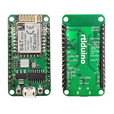
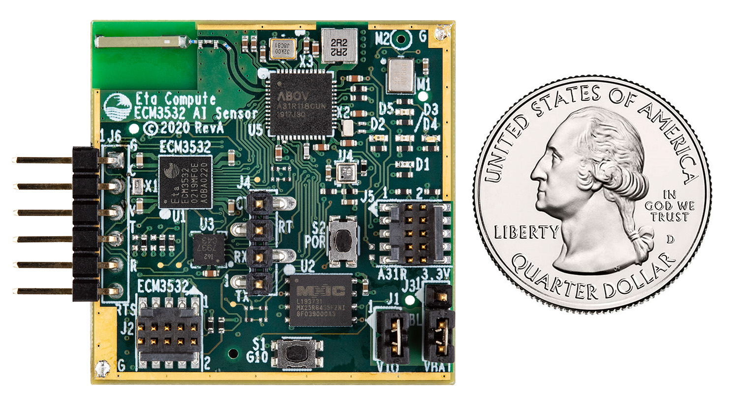
Eta Compute’s ECM3532 AI Sensor board is a low-power AI development platform with advanced sensors, compatible with sound classification, keyword spotting, activity classification, context awareness, and defect detection. It has an embedded Cortex-M3 microcontroller that functions up to a frequency of 100 Mhz, and NXP CoolFlux 16-bit DSP dedicated for machine learning using TinyML technology.

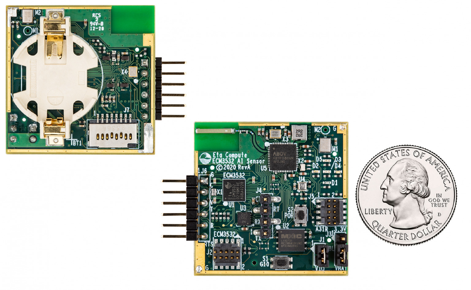
The AI sensor board integrates two microphones, one pressure and temperature sensor, and one 6-axis MEMS accelerometer and gyroscope. The ECM3532 AI sensor board also comes with small form factor with 1.4” x 1.4” dimensions, a built-in battery socket, and flexible Bluetooth connectivity with the A31R118 chip, this makes it suitable for IoT deployment and experimentation of application prototypes. The AI sensor board also has an expansion connector that simplifies the addition of other RF interfaces.

Key Features

  • Arm Cortex-M3 core works up to 100 MHz with less than 5μA/MHz run mode
  • Integrated 512KB FLASH, 256KB SRAM, and 8KB BootROM
  • NXP CoolFlux 16-bit DSP with 32KB program memory, 64KB data memory
  • 2 x PDM MEMS Microphones: TDK-Invensense ICS-41350
  • 1 x Pressure/Temperature sensor: BOSCH BMP388
  • 1 x 6-axis MEMS Accel/Gyro: TDK-Invensense ICM-20602
  • Battery cradle for a CR2032 battery
  • Bluetooth Low Energy on board: BLE v4.2: ABOV A31R118 and antenna
  • Extension for other types of RF through Micro SD card slot
  • 6 pin UART and power port
  • 64Mbit serial Flash for data logging
  • 5 LEDs and push-button

It performs efficiently with Neural Networks due to ECM3532 Neural Sensor Processor built with unique self-timed continuous voltage and frequency scaling at the run time using Eta Compute’s CVFS technology. This produces optimized energy for inference of machine learning and deep learning algorithms. It also supports Edge Impulse for data sampling, building models, and deploying trained ML models.

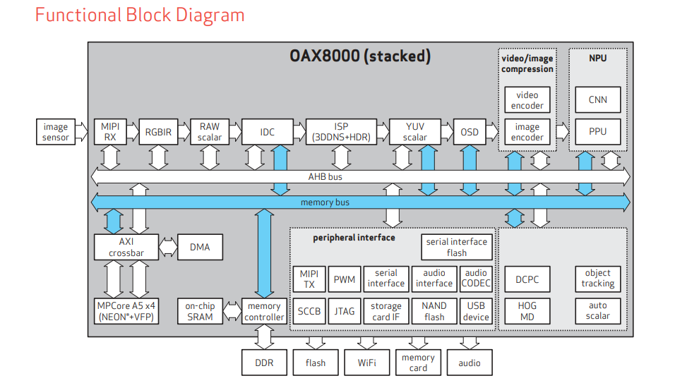
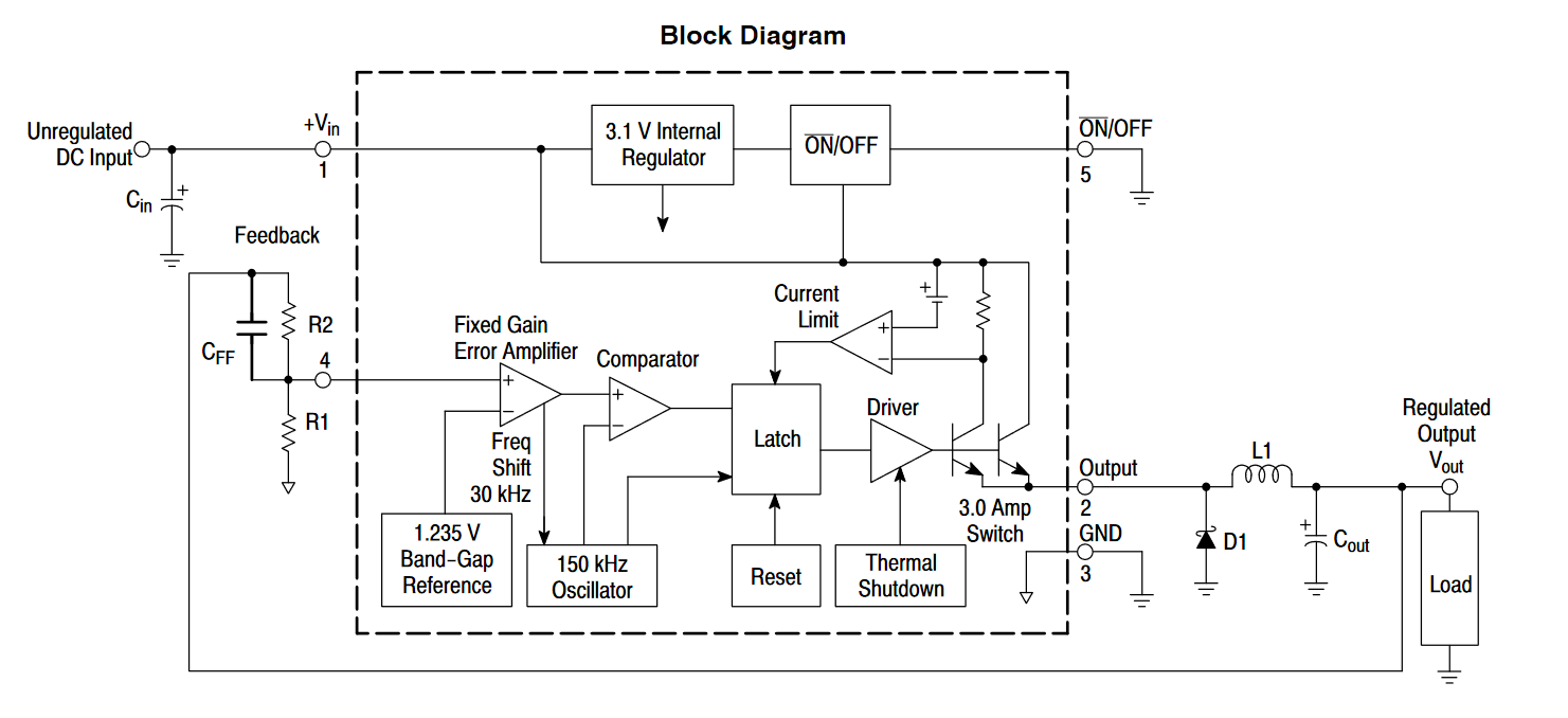
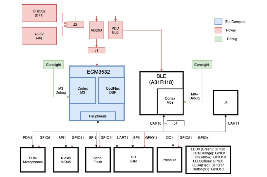
Block Diagram of  AI Sensor Board

Block Diagram of ECM3532 AI Sensor Board

Developing applications on the board requires Node.js version 12 or above, along with the Edge Impulse CLI version 1.7.0 or above as its dependencies. ECM3532 AI Sensor board includes a SparkFun FTDI Basic Breakout – 3.3V board in the box. This can be used to program the AI sensor and to relay serial messages back to the computer source. The FTDI cable can also be used for USB to serial TTL level conversion, by ensuring 3.3 V outputs as the sensors are not 5V tolerant.

ECM3532 AI Sensor board is versatile and features quick usage by Edge Impulse’s TinyML development pipeline and the 6 pin UART port. The board also comes with serial wire debug (SWD) CoreSight connectors for both the ECM3532 and the A31R118 for debugging. For this, a separate JLink or Ulink probe is needed.

The Edge Impulse firmware for the sensor board is open source and hosted on GitHub. For more information, you can visit the official product page. The ECM3532 AI sensor board is available on Digikey for $99. Images and technical specifications have been taken from the official product page and datasheet.

OAX8000 ASIC AI-enabled Processor for Driver Monitoring Systems

OAX8000 is an automotive ASIC optimized for dedicated DMS (Driver Monitoring Systems). The ASIC comes with a stacked-die architecture with multiple layers of ICs that offers on-chip DDR3 SDRAM memory (1GB). It also features a fast AI video processor with CNN (Convolutional Neural Network) accelerator and works as a low-power device. The automotive image sensors have a power rating of 1 watt.

The AI-enabled OAX8000 ASIC integrates an NPU and ISP (Image Signal Processor), which performs up to 1.1 TOPS for eye gaze and eye tracking algorithms. This integration also reduces the board area for the ECU (Engine Control Unit) by optimization of DMS systems. OAX8000 ASIC has a quick boot-up time that minimizes the delay between ignition and activation of the DMS camera. It also comes with secured boot functionalities for cybersecurity.

Technical Specifications of OAX8000 ASIC

  • Power Supply: Core 0.9V, Analog 1.8V, DDR I/O 1.35V, PLL 1.8V
  • Operational from -40°C to 105°C ambient temperature
  • Operational from -40°C to 125°C junction temperature
  • Dimensions: 10mm x 10mm

OAX8000 ASIC has a built-in NPU that has flexible support of almost all deep learning frameworks and tools like TensorFlow, Caffe, MXNet, and ONNX. It also integrates quad Arm Cortex A5 CPU cores with Neon technology for enhanced video encoding and decoding with advanced video analytics algorithms. It also comes with hardware for image processing and RGB/IR processing.

The ASIC has a flexible input processing capacity that allows the sensing of widely contrasting bright and dark images, due to its HDR processing feature. Hence, the applications are dynamic that can function in the day as well as at night. The embedded video encoder allows up to 5 megapixels of captured data from automotive image sensors and outputs up to 2K resolution video at 30 frames per second.

Functional Block Diagram of OAX000 ASIC

Functional Diagram of OAX8000

The storage interface includes an I/O peripheral interface, that can be used with an external WiFi module. It also comes with a storage card peripheral interface with NAND flash parallel interface for 8-bit and 16-bit, with up to 8-bit BCH ECC. This flash serial interface can function with or without the ECC engine.

OAX8000 ASIC has a built-in 16-bit ADC and 16-bit mono DAC, with full-duplex audio, AGC, and noise cancellation. It also integrates an audio engine for audio recording and playback. The full-duplex audio serial interface supports left/right 16-bit data mode and various audio formats. The security engine supports AES, DES, and 3DES-based encryption/decryption. It also features secured booting of the device.

The new OAX8000 ASIC is integrated into a BGA196 package. For more information visit the official product page. The pricing and availability of the ASIC can be inquired on the region-based sales section on the website. Images and technical specifications have been also taken from the product page and datasheet.

Mezza-pede 1.0mm pitch SMT Connectors from Advanced Interconnections Corp

Mezza-pede® 1.0mm pitch SMT Connectors from Advanced Interconnections Corp. are designed for low profile board-to-board or flex cable-to-board applications where long-term reliability and a compact size are required. With Advanced’s enclosed screw-machined socket, 6-finger contact, and heavy gold plating, Mezza-pede® Connectors pass the 20-day mixed flowing gas (MFG) test required in many telecoms and other severe environment and long-life applications.

Our over-molded lead frame seals the surface mount leads to prevent solder wicking, ensuring a secure solder joint. The low stack height makes it ideal for tight mezzanine packaging applications.

Typical Applications

  • Tunable Laser power connector (flex cable to board)
  • Tunable Laser connector (board to board)
  • Transponder Board connector
  • Signal connector (flex cable to board)
  • Low profile board to board connector

Features

  • Low profile – board to board stack height (z-axis) options ranging from 2.9mm to 4.0mm (nom.).
  • Robust design features screw-machined terminals and multi-finger contacts with a per contact current rating of greater than 1 Amp at 80°C ambient.
  • Dual row configurations include 8, 14, 20, 30, or 36 total positions with other pin counts available on a customized basis.
  • Fits within existing board layouts.
  • Unique SMT lead frame and pin design prevent solder wicking, providing the highest quality solder joint at the PCB level.
  • SMT and thru-hole designs available.
  • Passed 20-Day MFG test with heavy Gold terminal plating (GH).
  • Qualified for use in telecommunications applications.
  • RoHS Compliant
  • Request a sample, watch a video, or build a part number online at www.advanced.com

more information: www.advanced.com

ASRock Industrial Announces the IMB-V2000 Mini-ITX Motherboard Powering the Edge

ASRock Industrial Computer, the world leader in industrial motherboards and systems launches the new IMB-V2000 Mini-ITX motherboard, powered by AMD Ryzen™ Embedded V2000 Series Processors for a generational leap in performance. Featuring quad-displays with AMD multi-display Eyefinity technology, IMB-V2000 supports ECC memory, dual LAN ports up to 2.5GbE along with Dash and Teaming function as well as longevity support. It is well suited for a wide range of Edge applications, such as video walls, digital signage, the gateway in automation, automotive, and many more.

IMB-V2000 with AMD Ryzen™ Embedded V2000 to Power the Edge

The newly released IMB-V2000 Mini-ITX motherboard offers a new class of performance in a compact size. Available models include IMB-V2000P, IMB-V2000S, IMB-V2000M, and IMB-V2000V powered by AMD Ryzen™ Embedded V2748/ V2546/ V2718/ V2516 processors, up to 54W to project towards the future of optimal performance in Edge computing. AMD Ryzen™ Embedded V2000’s longevity support also enables the IMB-V2000 to provide customers with solutions designed for long-lifecycles. Moreover, for high-demand computing capabilities, the IMB-V2000 supports two 260-pin ECC/non-ECC SO-DIMM DDR4 3200 MHz up to 64GB of memory, and dual storages with one M.2 (Key M, 2242/2260/2280) with SATA3 and PCle x4 for SSD and two SATA3 for SSD/HDD, making it easy to carry out necessary upgrades.

Quad-displays with AMD Eyefinity technology for video wall and digital signage

Built to meet the ever-growing demands for Edge computing in the video wall, digital signage, gateway in automation, and automotive, the IMB-V2000 offers quad-displays with one LVDS, one eDP, three DP1.2, one DP1.4 plus the AMD multi-display Eyefinity technology to beyond the boundaries of traditional displays for a phenomenal visual experience. The motherboard is equipped with one Realtek 2.5 Gigabit LAN and one Realtek 1 Gigabit LAN high-speed connectivity, supporting Dash and Teaming function. Moreover, with feature-rich IOs and expansion slots, it provides four USB 3.2 Gen1, four USB 2.0, one M.2 Key E for wireless, one M.2 Key B for 4G/5G, one PCle x8, and five COM ports. With 12~28V DC-in lockable DC jack/ ATX PWR power input for versatile and wide-voltage Edge applications.

With the rapid growth of Edge computing platforms, ASRock Industrial works with AMD and effectively merges key features of the AMD Ryzen™ Embedded V2000 processors on AMD multi-display Eyefinity technology, ECC memory, and longevity support to bring in new product series in form factors of IMB-V2000 Mini-ITX Motherboard, 4X4-V2000 Motherboard, and iBOX-V2000 Series Mini PCs for a new class of performance with 7nm technology, extended scalability, and support that is strong in integration and enablement for Edge, embedded and industrial applications.

Features:

  • AMD Ryzen™ Embedded V2000 SoC processors
  • 2 x 260-pin ECC/non-ECC SO-DIMM DDR4 3200 MHz, up to 64GB (32GB per DIMM)
  • 4 x USB 3.2 Gen1, 4 x USB 2.0, 1 x M.2 Key E, 1 x M.2 Key M, 1 x M.2 Key B, 1 x PCIe x8, 5 x COM, 2 x SATA3
  • 1 x Realtek 1 Gigabit LAN (Support DASH), 1 x Realtek 2.5 Gigabit LAN
  • Support Quad display, 1 x LVDS, 1 x eDP, 3 x DP 1.2, 1 x DP 1.4
  • TPM header
  • Support DASH, Teaming funciton
  • 12~28V DC-In (Lockable DC Jack)/ ATX PWR

more information: https://www.asrockind.com/IMB-V2000

1.2V to 35V @ 3A Adjustable Step-down Regulator using LM2596

This is a highly efficient and compact project that is capable of driving a 3A load with excellent line and load regulation and adjustable output of 1.2V to 35V DC.  The project is built around the LM2596-ADJ regulator which is ideally suited for easy and convenient design of step-down switching regulator using buck converter topology. The adjustable output version of LM2596 is internally compensated to minimize the number of external components to simplify the power supply design.

LM2596 – 3.0 A, Step-Down Switching Regulator

The LM2596 regulator is a monolithic integrated circuit ideally suited for easy and convenient design of a step−down switching regulator (buck converter). It is capable of driving a 3.0 A load with excellent line and load regulation. This device is available in adjustable output version and it is internally compensated to minimize the number of external components to simplify the power supply design. Since LM2596 converter is a switch−mode power supply, its efficiency is significantly higher in comparison with popular three−terminal linear regulators, especially with higher input voltages. The LM2596 operates at a switching frequency of 150 kHz thus allowing smaller sized filter components than what would be needed with lower frequency switching regulators. Available in a standard5−lead TO−220 package with several different lead bend options, and D2PAK surface-mount package. The other features include a guaranteed 4% tolerance on output voltage within specified input voltages and output load conditions, and +/-15% on the oscillator frequency. External shutdown is included, featuring 80 uA (typical) standby current. Self-protection features include switch cycle−by−cycle current limit for the output switch, as well as thermal shutdown for complete protection under fault conditions.

Features

  • Adjustable Output Voltage Range 1.23 V to 35 V
  • Guaranteed 3 A Output Load Current
  • Wide Input Voltage Range 3.2V to 40 V
  • Input must be >1.5V higher than the output
  • High Efficiency Up to 92%
  • 150 kHz Fixed Frequency Internal Oscillator
  • Thermal Shutdown and Current Limit Protection
  • Internal Loop Compensation
  • Precise potentiometer for voltage adjustment
  • Output Ripple: ≤100mV
  • PCB dimensions 57.15 x 44.34 mm

Schematic

Block Diagram

Pin Out

Parts List

PartValuePackageLCSC.com
R150k ±10% Precision PotTHC118911
R21.21K 1%SMD 0805C228373
R34k7SMD 0805C229219
L133uH/5ASMD 12MM INDUCTORC439422
C2 C3220uF/50VSMD ELECTROLYTICC3358
C1100uF/50VSMD ELECTROLYTICC249588
IC1LM2596-ADJTO263 SMDC29781
D1MBRS340T3SMCC40326
D2RED LEDSMD 0805C192318
CN1 CN22 PIN SCREW TERMINALSTHC409161

Connections

Gerber View

Measurements

CH1: Output Voltage ripple with 30V Input and 12V @ 1A output – 277 mVpp
CH1: Output Voltage ripple with 30V Input and 12V @ 1A output – 277mVpp – CH2: Output at PIN 2 of IC – 156kHz switching frequency
CH1: Output Voltage ripple with 30V Input and 12V @ 3A output – 233 mVpp
CH1: Output Voltage ripple with 30V Input and 12V @ 3A output – CH2: Output at PIN 2 of IC – 147kHz switching frequency


Thermal Performance

30V Input and 12V @ 1A output -reaches close to 50 Celsius
30V Input and 12V @ 3A output – reaches close to 90 Celsius

Photos


Video

LM2596-ADJ Datasheet

TinyDecoder – Cool IR Receiver and NEC Decoder with Arduino

Infrared has been around for a long while. It has proven to be reliable enough so that basically almost everything remote and short range, that came before home automation was cool enough to be considered a thing, and battled its place fairly with RF technologies, so it deserves some love and affection from us. Besides that, it still has its own place, because our remotes and (specially) the old devices we like to hack still use it as a means for communication. Hence, understanding its internals is very useful, even to this day, and can be a good gateway for you into the IR world. Today, we will take a small glance at one of the most popular IR communication protocols and a device that will help you hack the IR devices all around you, the TinyDecoder!

Starting with the NEC, it is a standard protocol for sending and receiving data, used in IR remotes. It consists of 32-bit messages, with the address, its complement, the command and its complement, with each occupying 8 bits. Each message sent has the following sequence: 13.5 ms pulse, a 4.5 ms space and the message, with a 562.5 us pulse in the end of the transmission. The logical ‘0’ is represented by a 562.5 us pulse and another 562.5 us space, and the logical ‘1’ by a 562.5 us pulse and a 1.6875 ms space. Lastly, there are already tabulated values for the usual remote functions (changing channels, play, pause, numbers, etc).

NEC protocol message format

Now that you know how it works, let us have a look at the star of the show, the TinyDecoder. It consists of an IR remote receiver and decoder for the NEC protocol, using the ATtiny13A. On Wagiminator’s project (hosted on GitHub), which receives an IR signal via the TSOP4838 IR sensor, decodes the NEC protocol (including its extended version) and displays its address and command in an SSD1306 OLED display. It is powered by a small coin cell battery and everything about it is open-source, so you have access to the PCB files and the Arduino code. It can be a very useful tool if you intend to hack some devices.

The TinyDecoder in action

Lastly, there is a small limitation: NEC is not the only IR protocol you may want to tap into. There are other major protocols, such as the SIRC (Sony Infrared Remote Control) and RC-5, that you should learn about, and the 1 kB of Flash is deemed too small for that experience. So, you can switch to another ATtiny in the same package (such as the ATtiny85) and tap into them too, and there is already software support for it. So, why not give it all a try?

TinyDecoder GitHub link: https://github.com/wagiminator/ATtiny13-TinyDecoder

Downsize Your Bench Power Supply With the R4K-36 Series

In a time where we spend all our time at home, we start looking for ways to enhance our productivity. You may believe that nothing will ever beat your lab at work or college, and let me tell you, you are dead wrong! Today we will take a look at a very convenient palm-sized variable DC power supply, which has the potential to make your work at home more enjoyable!

The R4K-36 product, developed by Matsusada Precision, is a lab bench power supply series with the features you expect from one, but with a simple characteristic that makes a world of difference: it is incredibly compact. If you recall, these power supplies usually take up more space than almost any other appliance in the lab, and with this one, the space problem simply goes away, you can just tuck it anywhere and it will blend with the environment. 

But of course, a power supply is not just made of its size, so what is there that may deserve my attention (and money)? We will see:

  • Multi setting function, to memorize 3 different voltage and current settings
  • Delay trigger function, to delay the output in a range of 0.0 to 99.9 seconds
  • Two different locking modes, to avoid mis-operation and those accidental knob-bumbs
  • Sink current + sink current prevention function
  • Connection of up to 16 PSU’s in series (if you have them, you probably just need 2, one for positive and the other for negative rails)
  • Dual tracking, with multiple outputs
  • Digital interfaces available
  • Remote on-off control and remote sensing
  • Pulse and ramp sequences + master follow function (optional)

Besides these “nice to have” features, there are some technical details we should get into:

  • Voltage range from 2 to 40 V (with 1 mV resolution)
  • Maximum output power from 0.2 to 36 W
  • Maximum current from 0.1 to 4 A (with 0.1 mA resolution)
  • Four-digit meter
  • Dimensions: small enough to fit on your hand, do you need more detail?
The R4K-36 series (hand for reference)

A very important caveat, these features do not relate to all products in the series. There are many products in this series and they may not fill all the voltages, currents and power specifications stated here.

So, from what we have seen, we are looking at a small product capable of doing big things. It has most of the features you would need in a power supply for your lab and would suit you well. Regarding the price, it is only available through quote, which is a bummer, considering it is a critical factor when choosing a product. Just as a reminder, there are a lot of different variants to choose from, so if you go forward and actually buy one, take some time to analyze and choose the one that will work best for you.

Front and back of the R4K-36 series

R4K-36 series link: https://www.matsusada.com/product/dcps/handy/r4k36/

Rtlduino RTL8720DN Dual-Band WiFi Board With 2.4/5GHz Wireless MCU Sells for $6

Before now, most of the WiFi modules that we come across in the IoT space are the ones that work at only 2.4GHz. But things are fast-changing and we are beginning to see a number of them offering dual-band (2.4GHz and 5Ghz) WiFi, one of which is the B&T BW16 dual-band IoT module.

The B&T BW16 module is based on the Realtek RTL8720DN wireless MCU and sells for $3.90 minus shipping fees. If you like how cheap it is and you are interested in it but do not feel like soldering wires or creating your own baseboard, then you will be glad to further meet the new dual-band IoT board called Rtlduino RTL8720DN.

The Rtlduino RTL8720DN in a compact form factor is fitted with a B&T BW16 module and offers an easy way to evaluate the RTL8720DN dual-band WiFi and Bluetooth LE 5.0 microcontroller. The Rtlduino RTL8720DN board is also affordable and sells for only $6 plus shipping.

Here are some of the key features and specifications that the Rtlduino RTL8720DN board has:

  • B&T BW16 wireless module with:
    • Realtek RTL8720DN MCU with KM4 Arm Cortex-M4 core @ 200 MHz and KM0 Arm Cortex-M0 core @ 20 MHz
    • WiFi 2.4G and WiFi 5G with protocol 802.11 a/b/g/n 1×1 from 20/40 MHz up to MCS7
    • WiFi low power mode support
    • Bluetooth 5.0 LE support with a frequency range of 2.402GHz – 2.480GHz; Receiver sensitivity of -92 dBm; Transmit Power of +7 dBm
    • IPEX connector or PCB Antenna
    • 16x castellated holes with GPIO, 2x UART, 1x I2C, 1x SPI, 4x PWM, 1x ADC, 3.3V, GND, and,
    • 3.3 ±5% supply voltage.
    • Temperature Range: From -20°C to 85°C (operating);  from -40°C to 125°C (storage)
    • Relative Humidity: 10% ~ 90%
    • Dimensions: 24 mm x 16 mm x 3 mm
    • Certifications: FCC, CE, RoHS, and, SRRC
  • 1x Micro USB port
  • 2x 15-pin headers with BW16 I/Os
  • Reset button
  • Burn button
  • RGB LED
  • 5V power supply via Micro USB port
  • Dimensions: 49 mm x 26 mm

If you’re interested in getting one, the Rtlduino RTL8720DN board is currently available and can be purchased at $6 (with shipping) on Aliexpress.

You will find the SDK and a getting started guide that explains how to get started in Windows or Linux here, but if you want a detailed explanation on how to use the board with Arduino IDE plus sample codes for blinking an LED, you can check Arduino China forum or the ambd_arduino repo on Github if you prefer English. Thanks to the person nicknamed “a2302004040” for helping out with most of the explanations.

tKINO-ULT6: A Thin Mini-ITX Tiger Lake SBC With Dual 2.5GbE and USB 4.0

IEI has launched a thin Mini-ITX SBC with the latest 11th Gen Intel® Core™ processors that offer improved performance, power efficiency, and DDR4-3200 memory support.

The new board named tKINO-ULT6 seeks to break the boundaries of performance by bringing cutting edge features and ultimate performance to designs. It is among the first set of thin mini-ITX boards to be based on Intel’s 10nm fabricated 11th Gen Tiger Lake processors and also the second Tiger Lake SBC to come with a USB 4 port following Aaeon’s UP Xtreme i11.

The tKINO-ULT6 offers up to four simultaneous 4K displays, dual 2.5GbE ports, 10Gbps USB 3.2 Gen2 ports on the coastline, and a USB 4 that has a minimum of 20Gbps throughput and a maximum of 40Gbps.

The board also supports the more embedded Tiger Lake ULP “E” Core and Celeron variants. These “E” models are known to have an extended purchase availability and lower base and Turbo frequencies than other named ULP3 siblings without the “E” suffix.

tKINO-ULT6 can be used in a wide variety of applications like smart retail stores,  surveillance systems, digital signage, etc.

KEY FEATURES:

  • Has a thin Mini-ITX form factor with support for 11th Gen. Intel® Tiger Lake-UP3 processor
  • Supports a wide DC input range of 9V to 36V
  • Supports up to four independent displays (HDMI, DP, eDP/LVDS, USB4)
  • Has a dual Intel® 2.5GbE LAN
  • M.2 A key for WiFi+Bluetooth
  • M.2 M key for Storage (PCIe x2/SATA), and,
  • PCIe x8 Gen 4.0 slot

SPECIFICATIONS: 

  • CPU: 11th Gen. Intel® mobile Tiger Lake-UP3 on-board processor
  • 2x SO-DIMM DDR4 3200MHz up to 64GB
  • 1x M.2(NGFF)
  • 2x SATA
  • 1x CPU Cooler
  • 1x DisplayPort; 1x HDMI; 1x LVDS; Type-C DP
  • 2x 2.5GbE LAN powered by Intel I225V controllers
  • 1x Front Audio
  • Realtek ALC888S HD audio codec
  • 1 x M.2 2230 A key (PCIe x1/USB 2.0); 1 x M.2 2242/2280 M key (PCIe x2/SATA)
  • PCIe x8 Gen 4.0 slot (x4 signal)
  • 1x 8-bit Digital I/O
  • 5x External USB 3.2; 4x USB 3.2; 1x USB 4.0
  • 4x Internal RS-232; 1x Internal RS-232/422/485; 1x Internal RS-422/485
  • 4x Internal USB 2.0
  • 1x TPM 2.0 connector
  • Power Input: 9~36V DC input; 1x Internal power connector; Ø5.5mm External DC power Jack
  • Power Consumption: 12V @ 6.48A
  • Form Factor: Mini-ITX Motherboard
  • Dimensions: 170mm x 170mm
  • Operating Temperature: -20°C to 60°C
  • Storage Temperature: -30°C to 70°C
  • Humidity: 5% to 95% (non-condensing)
  • Certifications: CE/FCC compliant

The company did not say anything about the operating system but Linux and Windows will most likely be supported.

Further details including datasheet and file downloads may be found on their announcement page or product page.

+/-18V Isolated DC-DC Converter Dual Supply Output from USB 5V Power Input

This is a mini DC-DC converter with dual output from single 5V DC supply or USB power source (e.g., +/-18V from 5V/USB). The mini board will fit into small space and perform with high efficiency. Basically, the circuit transfers power from 5V/USB to the output side +/-18V with high isolation, without a direct connection between 5V/USB power and output. The power isolation prevents ground loops and provides high noise immunity between input and output. The project is based on SN6501 chip, which is oscillator/power-driver, is specifically designed for small factor devices. The device drives a low profile, center-tapped transformer primary from 5V/USB power and secondary side provides unregulated dual output which can be further regulated as per requirement (e.g., +/-5V, +/-12V). Project is a very easy and simple tool to test and run industrial, scientific project, PLC and I/O modules which require dual output from single input. D2 power LED, CN1 USB A type connector for USB power input, CN3 No isolated 3.3V and 5V DC output, CN2 unregulated dual 18V Output.

+/-18V Isolated DC-DC Converter Dual Supply Output from USB 5V Power Input – [Link]

TOP PCB Companies