uChip VGA 2.0 is an Open hardware DIY retro-gaming console

Itaca Innovation has launched a campaign on Crowdsupply for a DIY open hardware retro-gaming console called uSVC. The uSVC is a simple, DIY game console that enables you to create and play retro-style 8-bit games with standard USB controllers and keyboards. It comes as a kit, so you will need to assemble it, and you only need basic through-hole soldering skills to assemble it. The only thing you do not have to solder is the microSD card socket.

The uSVC can be viewed as:

  • A DIY soldering kit that is optimized for simplicity and fun
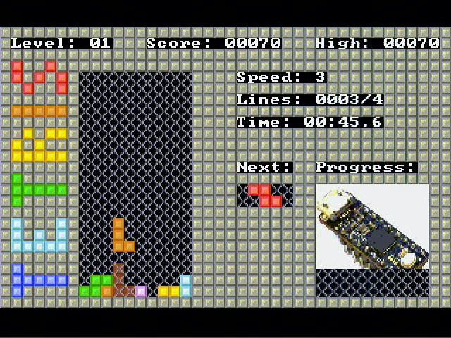
  • A retro-gaming console with three pre-installed games
  • An educational platform featuring a comprehensive Application Programming Interface (API), and a series of guides that will enable you design your own games in no time
  • A development framework that encompasses more than gaming use, but also with the expansion headers you can connect third-party peripherals, and you’ve got everything you need to design any number of low-cost devices that depend on USB connectivity and VGA output

The uSVC’s capabilities are a testament to the intricate technology that fuels both gaming consoles and digital entertainment platforms. It’s fascinating to think about how this technology parallels the complex systems that operate behind online gaming sites, like 빅토리카지노. It provides a rich, immersive experience with a vast array of games that cater to the preferences of diverse users, powered by similarly sophisticated software to ensure smooth and engaging gameplay. The dedication to delivering high-quality audiovisuals is paramount in both fields, ensuring that whether it’s gaming hardware or an online casino platform, users get the best experience possible.

Tiled modes support sprites with the following features:

  • Sprites up to 128 pixels in width or height are automatically handled by the graphics engine, so you don’t need to join smaller sprites to achieve larger ones
  • Up to 128 8×8 sprites can be drawn in one 256-color frame if they are 8-pixel aligned
  • For arbitrary alignment, up to 66 sprites can be displayed in one 256-color frame
  • All tiled modes support horizontal and vertical sprite flipping
  • The 256-color tiled mode supports 90°, 180°, and 270° sprite rotation and x/y swapping
  • By blending sprites and background graphics in 256-color mode, uSVC also supports partially transparent sprites that can be used to represent explosions, smoke, ghosts, and other lighting effects
  • Choose whether to give layer priority to sprites or tiles

The uSVC also features a smooth, full-screen, arbitrary-x/y scrolling in tiled modes. Its color-change engine for 16-color mode supports per-line changes to the entire palette or to any one of its 16 colors. Color-change also functions at high (400 line) resolution for smoother dithering effects and up to 256 on-screen colors. Its Per-line vertical row remapping feature enables you to produce reflection effects, such as water and split or flipped screens. Also, row remapping works at high (400 line) resolution. It also supports an optional, bottom- or top-fixed section to display status information such as a running score. About uSVC, the company says:

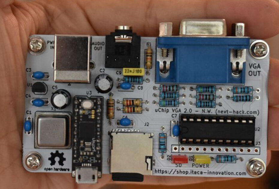
“uSVC is made up of a single chip and a handful of standard, through-hole components, so it’s perfect for beginning solderers. The only SMD component is the micro SD card reader, which we’ve pre-soldered onto the PCB. The tiny uChip that drives uSVC is, of course, fully assembled; you just have to slot it into its socket when you’re done putting everything else together.”

In the kit you will find:

  • One uChip with pre-soldered 카지노 사이트 headers and the open-source uSVC game loader pre-programmed. (The game loader sits on top of the standard uChip bootloader, so you can always repurpose the uChip for other projects and reflash the game loader on down the road.)
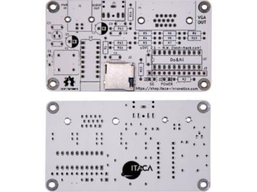
  • The PCB, with a pre-soldered SMD MicroSD card reader.
  • All of the components you will need to build your uSVC, including screws and spacers
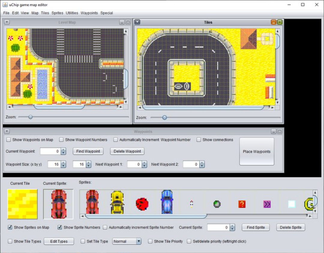
  • The Bill of Material (BOM) and assembly drawings. (Additional instructions, schematics, layouts, firmware, game code, and map editor code will be available on our website before the end of the campaign.)

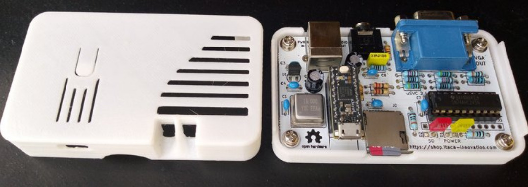
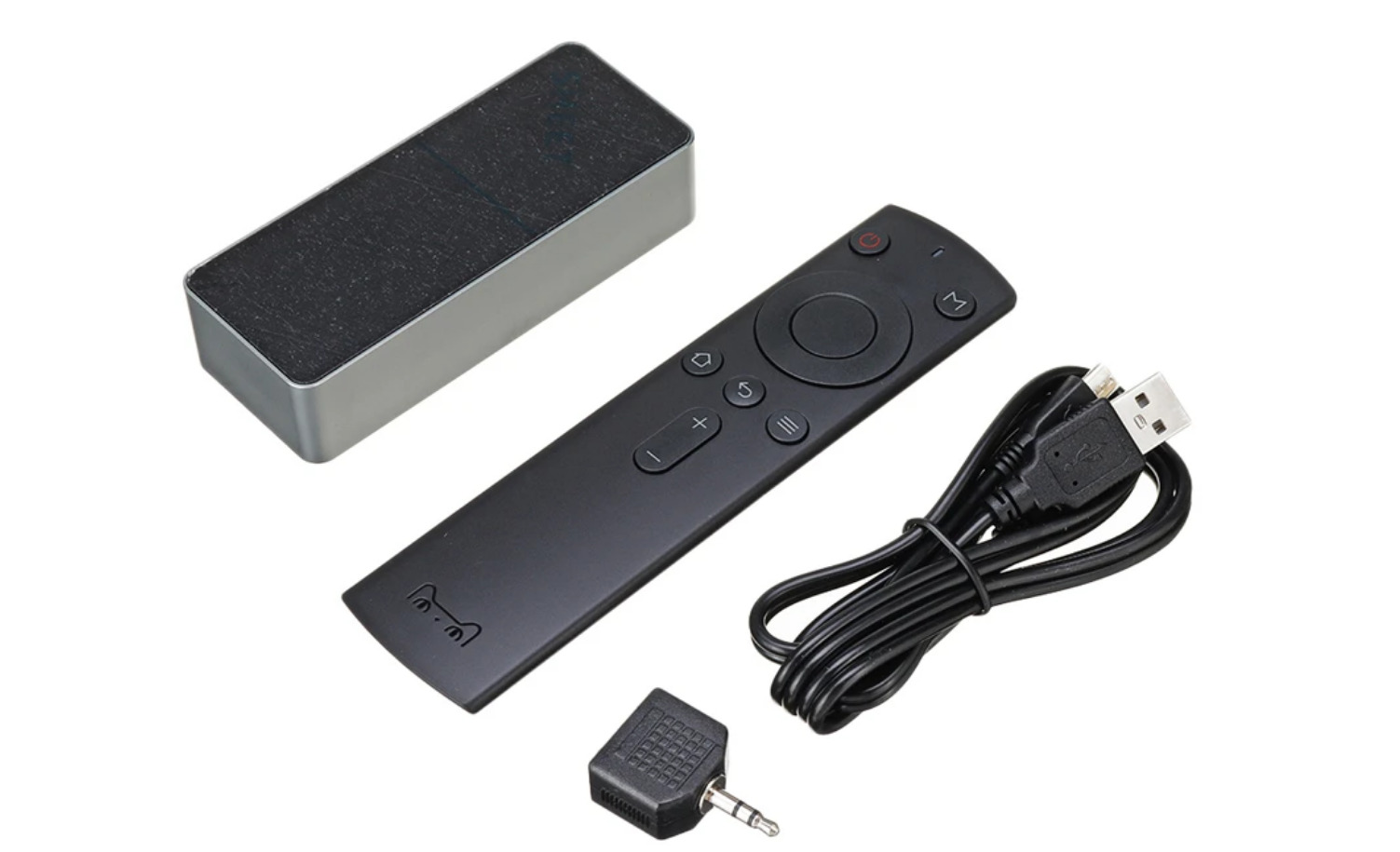
For the enclosure, if you can’t print your own, the company will provide a stylish, 3D-printed case—designed and printed by Stefano Rubini to the precise specifications of uSVC. They will also send a USB Type-B power cable, and a (female) USB Type-A to (male) Micro-USB data cable.

Technical Specifications:

  • uChip
  • ATSAMD21E18 @ 48 MHz
  • 256 kB of flash (232 kB available for the game)
  • 32 kB of RAM
  • MicroSD: Can store games and game data
  • VGA output: 57 Hz vertical frequency, 30 kHz horizontal frequency
  • Audio: 3.5 mm, 10 bit output jack
  • Controllers: Uses standard USB controllers and keyboards
  • Power Input: 5 V via USB cable, 100 mA (up to 80 mA observed)
  • Dimensions (W x L x H): 48 x 86 x 17 mm (without 1 cm hex standoffs or solder joints)

The uSVC is open source, and funding ends on Dec 03, 2020 at 03:59 PM PST (11:59 PM UTC). You can find more information on Crowdsupply.

RGB LED Controller using Atmega328

This is a 3-channel, PWM based current-adjustable LED driver designed for RGB LED control. The circuit has been designed to control high current RGB LEDs or RGB LEDs strip. Colors of the three RGB LEDs can be set using 3 potentiometers, different colors are possible by adjusting these potentiometers.

RGB LED consists of 3 separate LEDs red, green, blue packaged in a single case. The RGB LEDs can emit different colors by mixing three basic colours.

We have used ATmega328 microcontroller to generate 3 PWM signals by reading analog inputs. These analog inputs are connected to 3 potentiometers. PWM outputs interfaced with gates of 3 x IRLR7843 MOSFETs which drive the high current loads. MC78M05 IC used to power the Atmega328 chip with 5V DC. The operating voltage of this circuit is 12V DC and each channel can drive a continuous load current up to 600mA or 1 A with cool air. Screw terminals provided for an easy connection for RGB LED strip or RGB LEDs. The circuit can drive 12V RGB strip/12V RGB LEDs. Any RGB LED strip with RGB and +V connection will work with this board or use a common anode RGB LED.

This project is built using an Atmega328 microcontroller which requires programming, example code can be found below. This example code is written using Arduino IDE, thus the Atmega328 chip requires boot-loader burning and code uploading. Follow this link to learn Atmega328 Chip programming and Boot-Loader burning.

Note: RGB LED without series resistor can be interfaced with this board, in this case, calculate the series resistors R4, R8, R12 values. The default value of these resistors is 0-Ohms.  

Features

  • Supply 12V DC (7V-15V)
  • Load 600mA Each channel (1Amp with Fan)
  • 3x Potentiometer to Adjust 3X LEDs
  • PWM Duty Cycle Adjustable 0% to 100%
  • Frequency 490/975 Hz
  • Arduino Compatible Code
  • PCB Dimensions 61  X 67 mm

Schematic

Parts List

Connections


Gerber View

Photos

Video


Current Meter Using 0.96″ OLED Display

This project provides an economical and precise solution for DC current sensing and display on an OLED display. This board uses the ACS715T-20A hall effect-based linear current sensor chip, 0.96 Inch I2C OLED Display and Atmega328 microcontroller chip. It is an Arduino compatible open-source hardware that can be modified to your requirements. It is easily programable using the Arduino IDE. Connector CN2 is provided for Boot-Loader burning and programming of the Atmega328 chip using Arduino IDE. Refer to the wiring diagram below for programming and connections. The board can measure current up to 20A DC. Operating power supply 5V DC and it consumes approx. 20mA current.

ACS715 device consists of a precise, low-offset, linear Hall circuit with a copper conduction path located near the surface of the die. Applied current flowing through this copper conduction path generates a magnetic field which the Hall IC converts into a proportional voltage. Device accuracy is optimized through the close proximity of the magnetic signal to the Hall transducer. A precise, proportional voltage is provided by the low-offset, chopper-stabilized Bi-CMOS Hall IC, which is programmed for accuracy after packaging. The output of the device has a positive slope (>VIOUT(Q)) when an increasing current flows through the primary copper conduction path (from pins 1 and 2, to pins 3 and 4), which is the path used for current sampling. The internal resistance of this conductive path is 1.2 mΩ typical, providing low power loss. The thickness of the copper conductor allows survival of the device at up to 5× overcurrent conditions. The terminals of the conductive path are electrically isolated from the signal leads (pins 5 through 8). This allows the ACS715 to be used in applications requiring electrical isolation without the use of optoisolators or other costly isolation techniques.

Boot-Loader Burning & Arduino Programming

A new ATmega328 chip requires Boot-Loader burning and programming. The links below will help you to understand the process.

Example Arduino code is provided under the download section. This code will help you to test the project, we have tested with current up to 3A.

This board is made to measure current up to 5 A and you should use an appropriate thick wire for 20A current measurements.

Features

  • Power Supply 5V DC
  • Current Consumption 20mA Approx.
  • Current Measuring Range 0 to 20Amps (DC Only)
  • Sensitivity of ACS715-20A: 185mV/Amp
  • 5 µs output rise time in response to step input current
  • 80 kHz bandwidth
  • Total output error 1.5% typical at TA= 25°C
  • Small footprint, low-profile SOIC8 package
  • 1.2 mΩ internal conductor resistance
  • 2.1 kVRMS minimum isolation voltage from pins 1-4 to pins 5-8
  • 5.0 V, single supply operation
  • 133 to 185 mV/A output sensitivity
  • Output voltage proportional to DC currents

Schematic

Parts List

Arduino Programming Connections

Test Connection

Gerber View

Photos

Video

ACS715 Datasheet

Attiny85 8-pin Arduino Programming Shield

This Arduino shield transforms your Arduino UNO into an ISP-Programmer for the ATtiny85 microcontroller. The board simplifies the Boot-loader burning on the ATtiny85 chip. It consists of an 8-pin DIP socket to insert the new ATtiny85 chip, C1 decoupling capacitor, and C2 capacitor is provided to avoid the Arduino UNO from being auto-reset when we upload the program to the ATtiny85 chip. The project is a good choice when the user wants to shrink the Arduino project into an 8-pin microcontroller and when the project requires only a few I/O pins.

Few tutorials showing how to program the ATtiny85 from the Arduino IDE with the help of the Arduino Uno are listed below:

Video

Features:

  • PCB dimensions: 25 x 51.12 mm

Schematic

Parts List

Connection

ATtiny85 Pinout


Gerber View

Photos

Monolithic Power Systems’ 5 V USB, 1 A, I²C-controlled linear charger

The MP2667 from Monolithic Power Systems is a highly integrated, single-cell, Li-ion/Li-polymer battery charger with system power path management for space-limited portable applications. This device takes input power from either an AC adapter or a USB port to supply the system load and charge the battery simultaneously. The charger function features constant current pre-charge, constant current (CC) fast charge, and constant voltage (CV) regulation, charge termination, and auto-recharge. The power path management function ensures continuous power to the system by automatically selecting the input, battery, or both to power the system. This power stage features a low-dropout regulator from the input to the system and a 100 mΩ switch from the battery to the system. Power path management separates the charging current from the system load, which allows for proper charge termination and keeps the battery in full-charge mode.

The MP2667 provides a system short-circuit protection (SCP) function by limiting the current from the input to the system and the battery to the system. This feature is especially critical for preventing the Li-ion battery from being damaged due to excessively high currents. An on-chip battery undervoltage lockout (UVLO) cuts off the path between the battery and the system if the battery voltage drops below the programmable battery UVLO threshold preventing the Li-ion battery from being over-discharged. An integrated I2C control interface allows the MP2667 to program the charging parameters, such as the input current limit, input minimum voltage regulation, charging current, battery regulation voltage, safety timer, and battery UVLO, and is available in a QFN-10 (2 mm x 2 mm) package.

Features

  • I2C interface for programming charging parameters and status reporting
  • Fully integrated power switches and no external blocking diode required
  • Built-in robust charging protection including battery temperature monitoring and programmable timer
  • Built-in battery disconnection function for shipping mode
  • Thermal limiting regulation on the chip
  • Compatible with 5 V USB power sources fully autonomous charger for single-cell Li-Ion/Li-Polymer batteries
  • Complete power path management for simultaneously powering the system and charging the battery
  • Programmable input current limit and minimum input voltage regulation thresholds
  • ±0.5% charging voltage accuracy
  • 13 V maximum voltage for the input source
  • Available in a QFN-10 (2 mm x 2 mm) package

more information: https://www.monolithicpower.com/en/mp2667.html

Tiny Allwinner H3 Based Linux Development Kit Comes With SoM and Expansion Board

Seeed Studio provided Zhihui with a complete service from PCBA prototyping, customization, and consignment services, bring the product from idea to market. This has led to an open-source, Linux Development Kit with SoM and Expansion Board that runs Ubuntu Core on a quad-core Allwinner H3 called the Quantum Mini Linux Development Kit.

The SoM, Quark-N, is based on Allwinner H3, Quad-core Cortex-A7, and ARM Mali400 MP2 GPU. The carrier board, Atom-N, features an array of golden finger pins to enable I/O expansion, expand SPI, I2C, UART, GPIO, and other useful interfaces. The Quantum Mini Linux Dev. Kit is possibly the smallest Linux development board on the market. It is a highly integrated kit with quad-core CPU that can run Linux at only 40mm x 35mm, which also includes network connectivity. The development kit is suitable for scenarios such as a personal server, intelligent voice assistant, and for robotic development.

The SoM, which is called Quark-N is based on Allwinner H3, Quad-core Cortex-A7, and ARM Mali400 MP2 GPU. The 6-layer high-density gold PCB design integrates a complete ARM-Linux system (CPU, DDR, eMMC) in a 2x3cm space. Also, most of the GPIOs are connected on the board through the M.2 Key-A golden finger interface to minimize the bottom board design difficulty. However, you can design your own base plate with two-layer boards. The carrier board is called Atom-N, and Quark-N is connected to Atom-N via the M.2 interface. Atom-N features a row of golden finger pins to enable I/O expansion, expand SPI, I2C, UART, GPIO, and other interfaces to facilitate the completion of your own design. It is also equipped with a microphone, MPU6050 motion sensor (accelerometer and gyroscope), onboard 4 buttons (GPIO-KEY, Uboot, Recovery, Reset), IPS display, and Wi-Fi/Bluetooth connectivity which greatly expands the possibilities with this product.

The core features of the development kit include:

  • Ultra-small (31mmx22mm) and highly integrated Quad-core Cortex-A7 Linux SoM (System on Module)
  • Expansion board (40mmx35mm) with rich peripherals and interfaces: Microphone, Gyroscope, Accelerometer,4 x Buttons (GPIO-KEY,
  • Uboot, Recovery, Reset) and a TFT display
  • Integrates a complete ARM-Linux system for advanced development
  • Ability to design your own baseboard due to the M.2 interface
  • Wide range of applications such as a personal server, intelligent voice assistant, and robotic development.

Application of the development kit includes:

  • Microcomputer
  • Personal website server
  • Programming learning such as Python
  • Image processing
  • Robotics
  • Voice assistant
  • Smart home hub

Specifications listed for the Quantum Mini include:

  • Processor (via Quark-N module) — Allwinner H3 (4x Cortex-A7 @ 1.0GHz); Mali-400 MP2 GPU @600MHz; 256KB L1, 1MB L2 cache
  • Memory/storage:
    *512MB DDR3 SDRAM (via Quark-N)
    *16GB eMMC (via Quark-N), expandable to 64GB
    *MicroSD slot
  • Networking — 2.4GHz 802.11 b/g/n with Bluetooth 4.0 (Realtek RTL8723BU); Ethernet support available on Quark-N
  • Media I/O – TFT display; microphone
  • Other I/O:
    *2x USB 2.0 host ports
    *USB Type-C port with power input
    *8x golden finger pads with SPI, I2C, UART, GPIO, ADC, speaker, 5V, 3.3V, GND
  • Other features — Gyro/accelerometer (MPU6050); 4x buttons (GPIO-KEY, Uboot, Recovery, Reset)
  • Power – 5V via USB Type-C
  • Operating temperature — 0 to 80℃ for Quark-N
  • Dimensions — 40 x 35mm (31 x 22mm for Quark-N)
  • Operating system — Ubuntu Core

The development kit is a collaboration between Seeed and Zhihui, and they still want to collaborate with other developers. They say :

“If you have a design with great potential and think others would be interested in it, you can start with Seeed Fusion Marketplace. Seeed Fusion Marketplace is a great platform to make your PCBA product available to a worldwide audience without handling production and order processing. It can help you scout out the interest in your design and gauge its real market potential.”

The Quantum Mini is available for pre-order from Seeed at $49.90, with shipments due Dec. 20. More information may be found on Seeed’s shopping page and the Project Quantum GitHub page.

USB-C, DFP, 5V/3A Out, 85-265VAC In, Adapter, Low Cost Reference Design

The PMP11124 reference design uses the UCC28700 and TPS25810 to provide an isolated 5V at 3A over a USB type C interface. The UCC28700 implements primary-side regulation, eliminating the need for an opto-coupler and reducing the size and cost of the design. Cost is further minimized by using an output diode instead of a synchronous rectifier.

Features

  • USB type C interface
  • Minimal component count provides low cost solution
  • 3A capability advertisement on CC line
  • Meets class B conducted EMI limits

more information: https://www.ti.com/tool/PMP11124

Selpic Star A – A Cost-Effective Multifunctional mini 3D Printer

Star A: The Most Cost-Effective Multifunctional 3D Printer – An easy to install & operate 3D printer with touchscreen, laser engraving, and a multitude of features, starting from only $99.

Selpic Inc has launched a campaign on Kickstarter for a 3D printer called Star A. 3D printing has being around for a while now, gaining more popularity by the day, and getting more advanced by the day. Industries and individuals make use of 3D printing for their projects. However, technical know-how, the complexity of the operation, and the cost of 3D printers limit the use. However, Selpic Star A 3D Printer solves most of these problems.

Technical Details

The Star A is an ultra-compact and easy-to-use multifunctional 3D printer that enables open-source customization. With Star A, you can bring your ideas to life quickly and easily. With a 10.2″ x 9.4″ x 9.8″ form factor, the Star A only weighs 4.4 lbs, and it is built around a lightweight frame with a small footprint. Its small size enables you to place Star A in a small space, and you can move it around easily. Do not be fooled by its super-light body, the Star A is sturdy and durable, remaining completely stable when in operation. You do not have to be a technician to install the Star A. It is very easy to install. All you have to do is tighten the screws, connect 2 cables, and get ready to install the filament. Star A enables a 4-button operation. The 4 buttons enable you to reset, print (start, pause or cancel), feed filament, or release filament. The X-axis and Y-axis of Star A clocks an accuracy rate of 100 μm, and the Z-axis accuracy clocks at 50 μm. It offers a printing resolution of ±0.1 mm and the layer thickness is 0.1~0.2mm.

What makes Star A an efficient printer, is the direct extrusion technology it utilizes. The extrusion technology enables the printer to avoid filament stringing and oozing, making it achieve better extrusion and faster retraction. Another feature that makes the Star A effective is that its nozzle is made of brass. This makes the extrusion process smooth and stable because it has a smooth inner wall, excellent thermal conductivity, and constant temperature control. In a situation where there’s a power interruption or you run out of filament, Star A can resume printing.

printing a small vase

Install & set up

The printer is easy to install and setup. All you have to do is to attach the Z-axis on the Y plate and tight some screws. Then you connect some wires and load the filament. Filament load is done by pressing the + button, wait for the head to warm up, and then when ready press it once more. To extract it follow the opposite direction by pressing the – button. Among these, the control box contains 4 operating buttons which can help with an easy reset, printing, filament feed, and release. Star A supports wired-connected printing and wireless printing with TF-card insertion. You can create your own G-code file using some common open-source printer programs, such as Cura or Repetier-Host, and load it to the printer for a straight print. For installation and setup of Cura follow the steps on this PDF document. For more details on bed leveling, filament load and general setup of the printer refer to the PDF Manual.

printing of vase completed succesfully

Auto resume

The printer is designed to automatically stop and continue from where it left off once the problem is resolved. This helps you save filament and avoid wasted time and effort. You don’t have to worry about noise from the motor while printing Star A has an operating noise below 60db, which is very impressive. This means that you can keep it running in the background without worrying about the printer disturbing others or disrupting your work.

Laser Module

Another feature of Star A is its laser engraving capability. It has a laser engraving head installed, which enables it to engrave on multiple materials such as wood, plastic, or card. The company has made done a great deal to keep the machine stable while printing. The Z-axis screw of the printer helps to stabilize the machine and maintains the printing precision. The Star A is equipped with 4 strong springs that can help with leveling, 2 belts maintaining the printer’s stability, and 4 buttons that light up to aid use.

Add-ons

Another feature of Star A is that it supports add-ons. You can swap out the buttons for a 2.4-inch full-color highly sensitive touchscreen. You can also easily install the laser engraving head, and you can make use of an upgraded hotbed, which heats up to 100℃, and can take care of the higher requirements of some special filaments.

About modifications to Star A, the company says:

“In order to make the Selpic Star A be full of a sense of technology and premium, we will adopt a transparent glass-like design (Acrylic material) to replace its original prototype. The new design’s material will also be stronger and more wear-resistant. The printing volume will be expanded from the original 100*100*100mm to a larger 120*120*120mm.”

Selpic wants you to develop the Star A or DIY, so they are making the open-source code available, and more add-on accessories will be provided including a touch screen, laser engraving head, and hotbed.

Box Contents

The fine features and details of Star A makes it very effective and gives the user a lovely experience. It is not complex, and it’s easy to use.

The project will only be funded if it reaches its goal by Thu, December 3 2020 2:58 PM CET. You can find more information on Kickstarter.

Selpic Black Friday Deals up to 30% OFF

  • Activity Time: From Nov.23 to Nov.30
  • Activity Link: selpic.com

Update 30/1/2020:

Our first print on Selpic Star A is quite impressive in details

Infrared Remote-Controlled AC Load ON/OFF switch with SSR

Driving an AC high voltage and current load using an Infrared remote is very easy with this project. This is an open-source Arduino compatible hardware that is based on ATMEGA328 microcontroller, SSR (Solid-state Relay), Infrared Receiver TSOP1838, and analog input interface. We have used KSD215AC3 optically isolated solid-state relay to drive AC loads. We have tested this board with 200W/230V AC lamp, however, the load capacity of SSR is 15A. A snubber circuit is provided across the SSR-Triac which helps driving inductive loads. The heatsink on SSR is not required for loads up to 200W, however, for higher loads, it is advisable to mount SSR on a heatsink.  Analog input can be used in applications such as motor speed control feedback, Heater controller, Feedback switch, Closed-loop control system etc. Connector CN3 is provided for Arduino Boot Loader burning and Code programming with Arduino IDE.

Infrared Remote-Controlled AC Load ON/OFF switch with SSR – [Link]

Audio Spectrum Indicator and Digital Clock with Remote Control

Remember those good old days when everyone had those giant sound systems in their living room? Besides the inconvenience of the CDs, the sound experience was extremely fun, and they’re always was a small star in the show: the small screen with the VU animations. Unfortunately, they fell into the pile of old electronics, often being replaced by portable sound systems that barely ever incorporate that cool spectrum indicator. But now, you can have it back with the LINK1 AK7115, bringing those music spectrum and VU meter animations, clock functionality, among other cool features!

Videos

The LINK1 AK7115 is a small and discrete device that can most of the time be disguised as the clock in your bedroom, but it can be much more. With its old school VFD display, it supports 2 modes essentially: clock mode and music mode. The first one is self-explanatory, but the second is where the magic happens. It can act as a VU meter and a spectrum indicator for your music, just like old times. You might be wondering: I already have a good new sound system (maybe with those cool Bluetooth speakers), why would I switch? The answer is simple, you don’t. The LINK1 AK7115 only outputs the sound animations on the display, and no sound, which leads to our next topic.

How do you use such a thing? Firstly, you connect one of those USB chargers you have laying around the house, getting all dusty. The power supply is not included (reminds you of a certain company?), but there is the USB cable. Then, you use a 3.5mm 1 to 2 audio splitters, to connect one end to your audio output of choice and the other to the LINK1 AK7115. Now, here is a small caveat, but a big deal for a lot of people: Bluetooth is not going to work on this one. It is unfortunate, but not the end of the world. Looks like the device was not thought out to be used with them, but they are one of the most popular sound systems. But there is a small advantage: due to its very small size, you can install it into a power amplifier that does not have one (a little DIY, but do it safely, as the VFD can output a high DC voltage of around 5V) or place it near one permanently, and there you have a clock at all times and a pleasant visual sound animation whenever you want.

It also comes with a small remote control, so that you can switch modes easily, along with controlling the brightness, the clock and the music modes, with quite a lot of options, such as the mode effects, rising and falling speeds and other things, in what they describe as software AGC, custom output curve and a “unique spectrum smoothing algorithm to make the best balance between real and visual beauty”. Really cool touch!

System diagram for the LINK1 AK7115
box contents

Regarding the specifications of the LINK1 AK7115:

  • DC Input of 5 V and 600 mA
  • Interface: USB power and audio input
  • Sensitivity: -30 dB to +10 dB (1 kHz) in dB mode and -25 dB to +3 dB (1 kHz) in AS mode
  • Weight of 130 grams, with an aluminum shell
  • 71 x 15 VFD display
  • Dimensions: 105 mm x 42 mm x 22 mm

Lastly, let us discuss pricing: you can order it on Banggood for around $74.94, but is currently on sale for $67.97. Now, this is not the cheapest option ever, but with its old school vibes, the well thought out design and features it provides, it might be a solid option for you.

Buy LINK1 AK7115 on Banggood.com

TOP PCB Companies