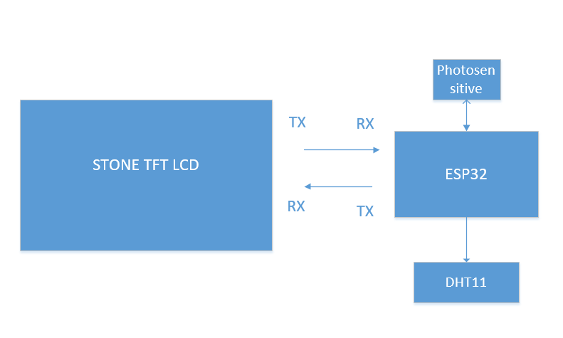
In the application of this paper, I will use the STONE TFT LCD screen, esp32 microprocessor, photosensitive resistance sensor, and DHT11 temperature and humidity sensor to realize the real-time monitoring of the surrounding environment and push the collected data to the TFT LCD screen for display. The communication mode of esp32 and STONE TFT LCD adopts serial port communication.
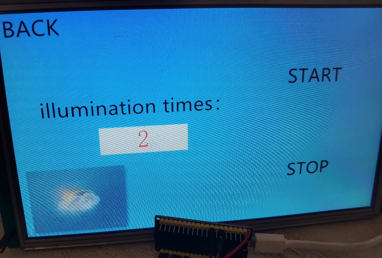
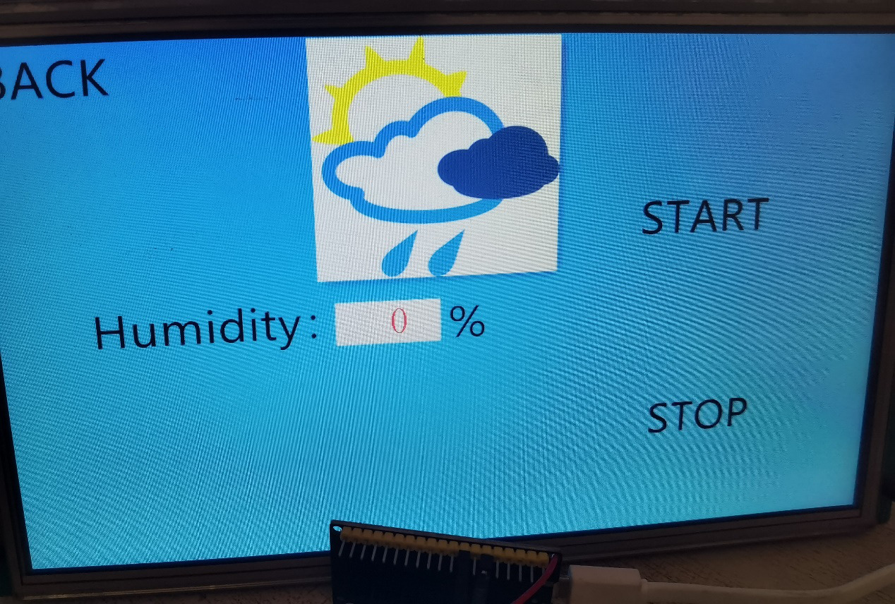
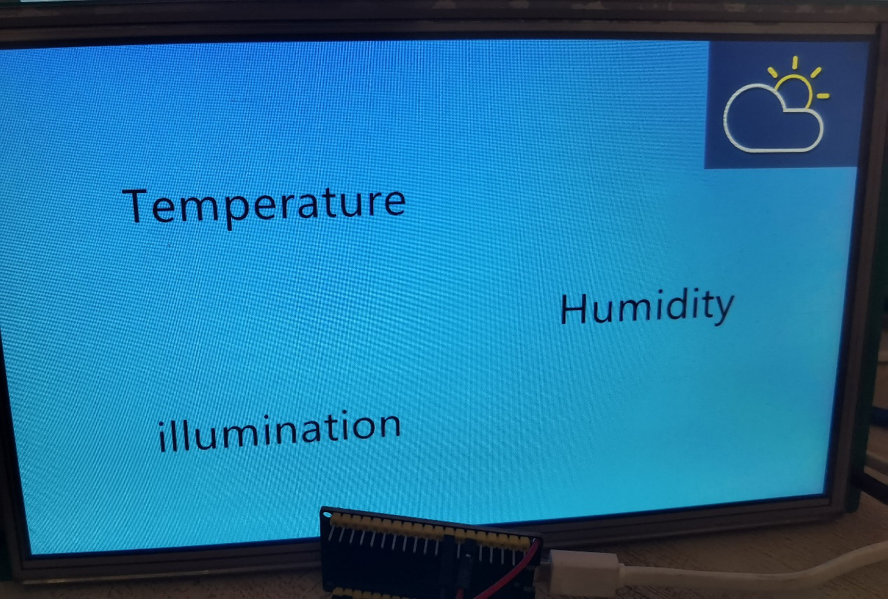
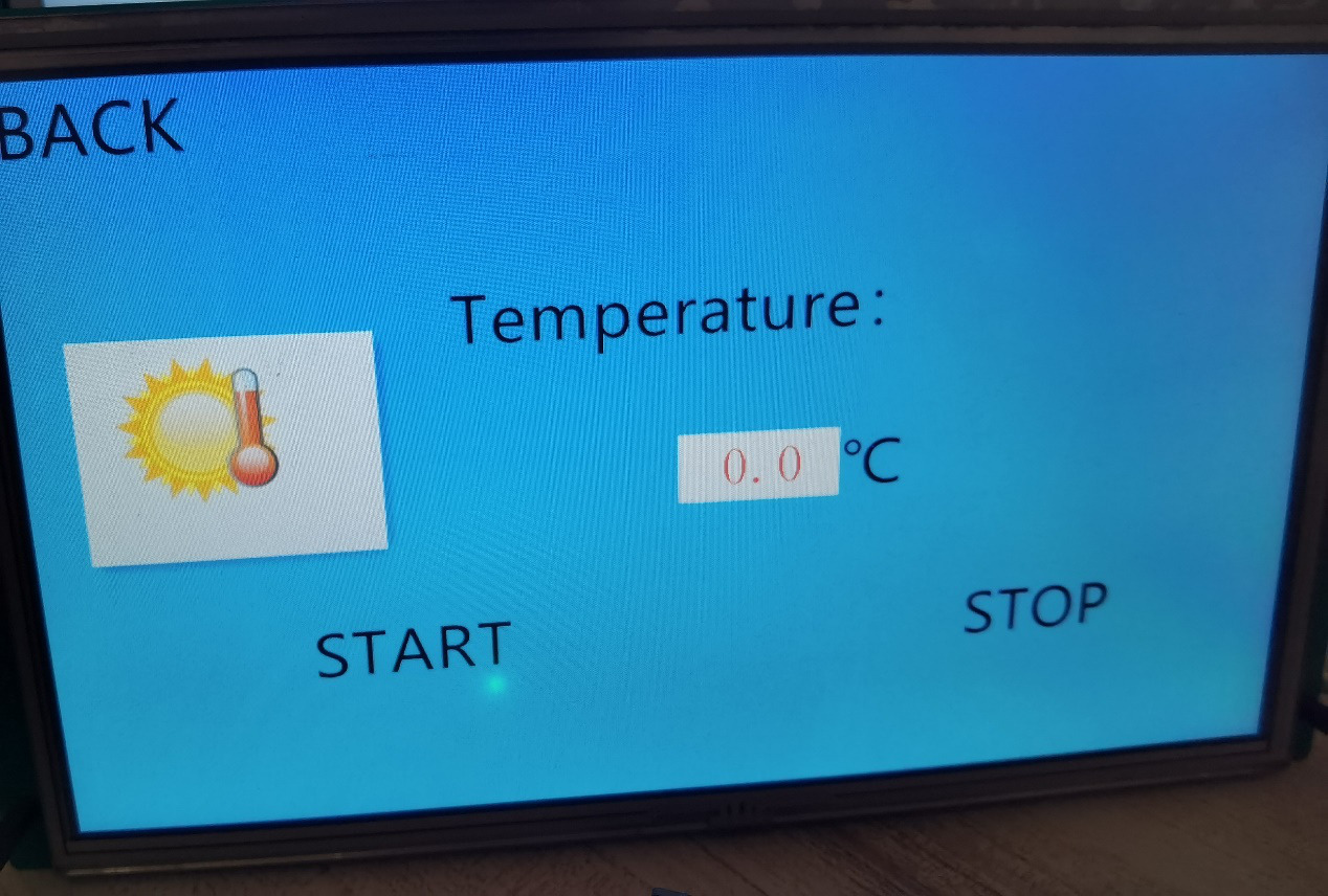
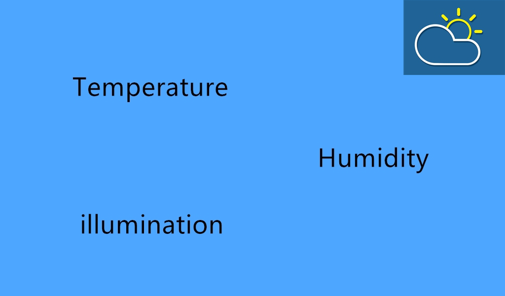
This application function is divided into three parts: temperature monitoring, humidity monitoring, and light monitoring. After startup, there will be a boot interface first. After a moment, you will enter the main function interface. In this interface, we can select the monitoring items, such as temperature, humidity and illumination. There will be a text box under the temperature monitoring interface to display the temperature data transmitted from esp32, a “start” button, and a “stop” button to start and stop the temperature monitoring. If you want to exit the interface, you can select the “return” button; the second item is humidity monitoring, and there is also a text box under this interface for displaying esp 32. For the humidity data transmitted, the “start” and “stop” buttons are used to start and stop monitoring, and a return button is used to exit the current interface. The third item is light intensity monitoring. Different from the previous two functions, counting is used here, and one is added every time there is light.
Design sketch:

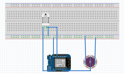
To make this application, first of all, on device selection, this application needs to use DHT11 temperature and humidity sensor, photosensitive resistance sensor, some DuPont wires, an esp32 as the main controller, and a STONE TFT LCD screen for communication with the MCU.
Related devices:
Information interaction between STONE TFT LCD and esp32:
- The serial port screen of STONE TFT LCD realizes the function of button switching interface;
- STONE TFT LCD serial port screen can automatically jump to the main interface after startup;
- The serial port screen of STONE TFT LCD realizes variable display function;
- The serial port screen of STONE TFT LCD realizes data variable distribution;
Esp32 peripheral control:
- Esp32 realizes the data acquisition and analysis of photosensitive resistance sensor;
- Esp32 realizes the data adoption and analysis of DHT11 temperature and humidity sensor;
- Esp32 can upload valid data to TFT LCD screen.
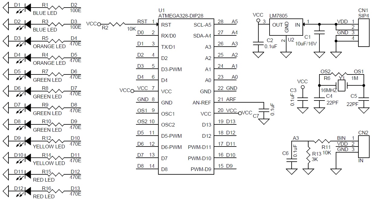
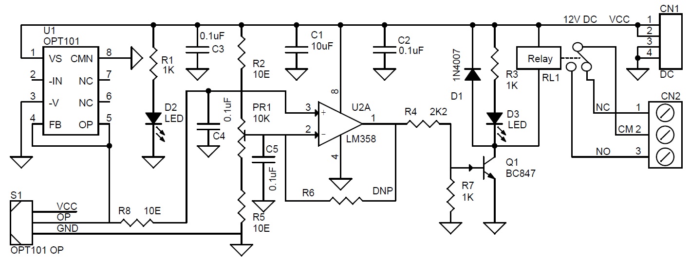
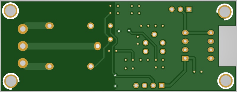
Brief schematic diagram of the project:
Module introduction
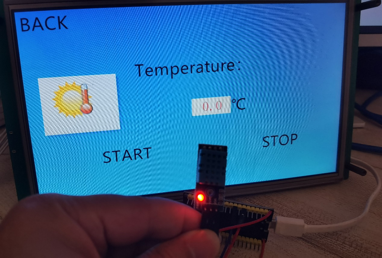
Temperature and humidity sensor
The DHT11 temperature sensor I use can monitor the temperature and humidity of the surrounding environment. The working voltage is 3.3V ~ 5V, and the signal output form is digital output. It is suitable for this project, but it is difficult to develop.
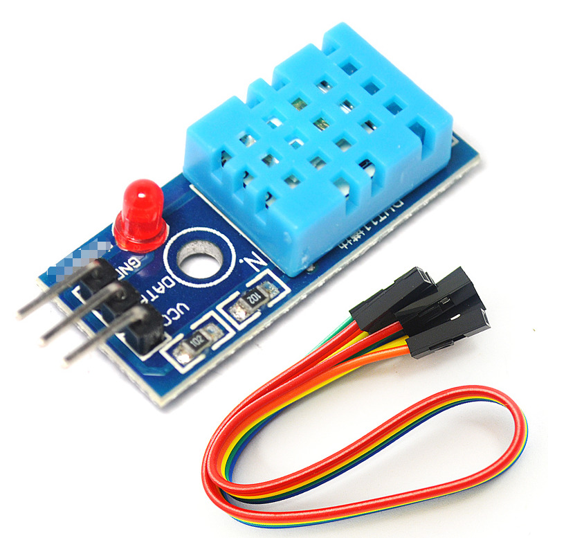
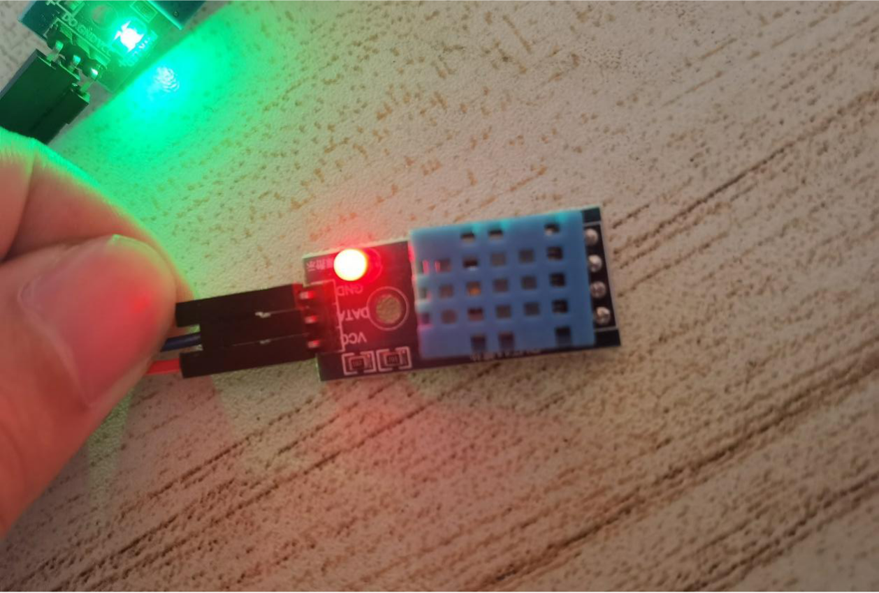
Because of the Arduino ide development, we must install “dhtnew.h” library to use this module.
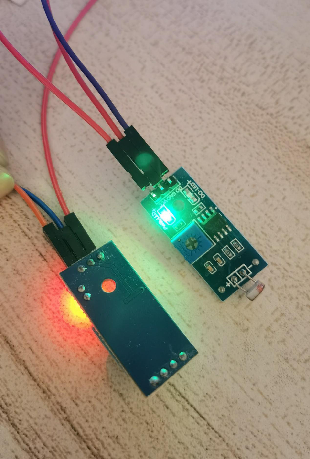
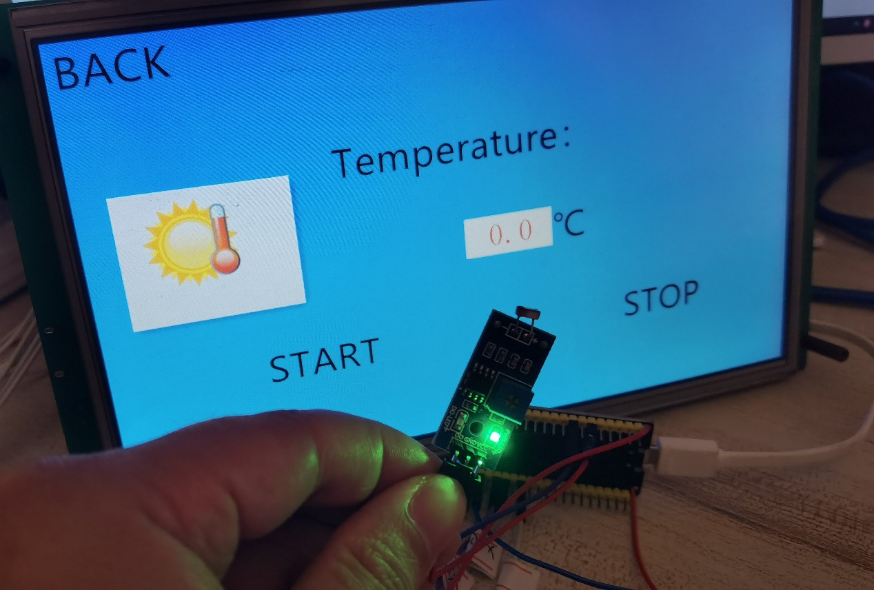
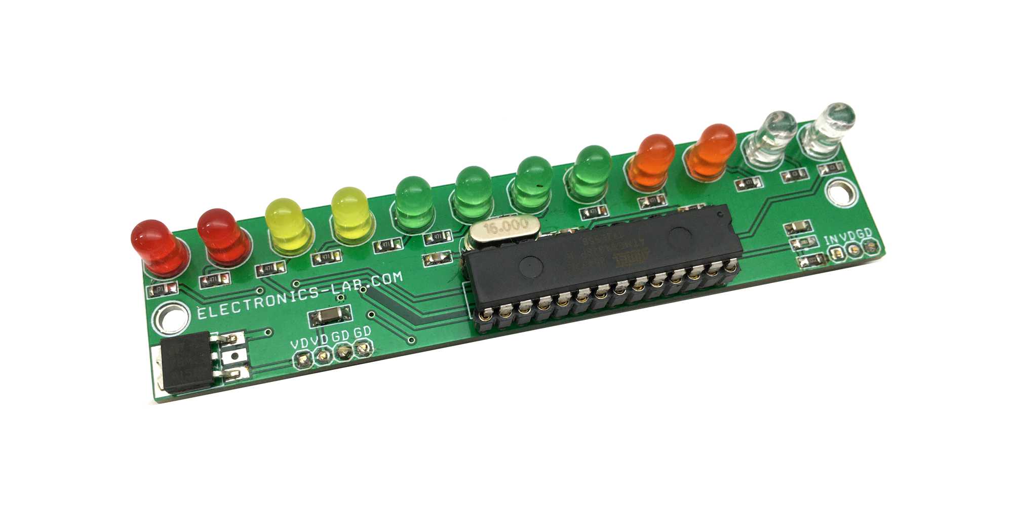
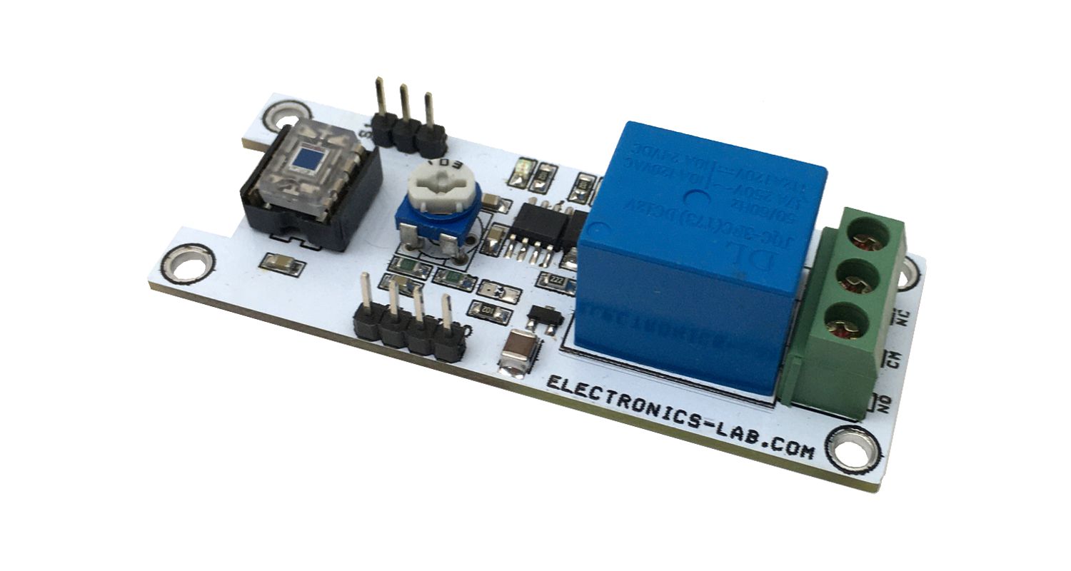
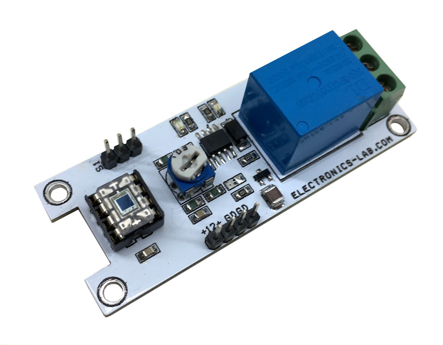
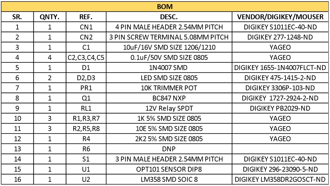
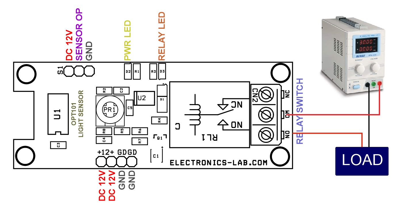
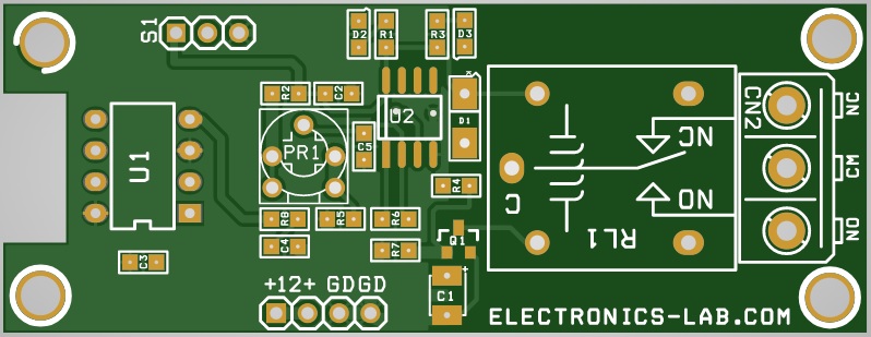
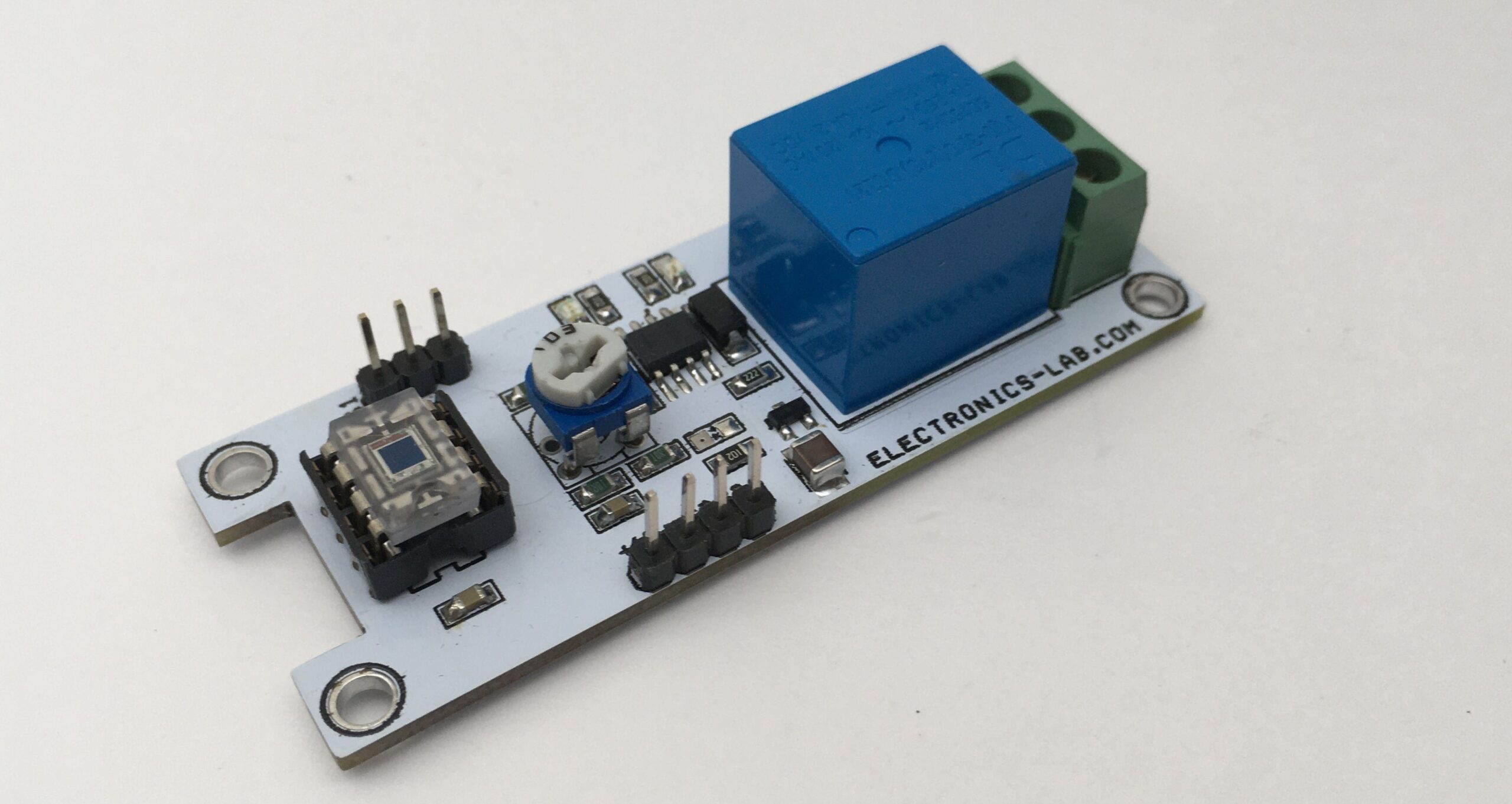
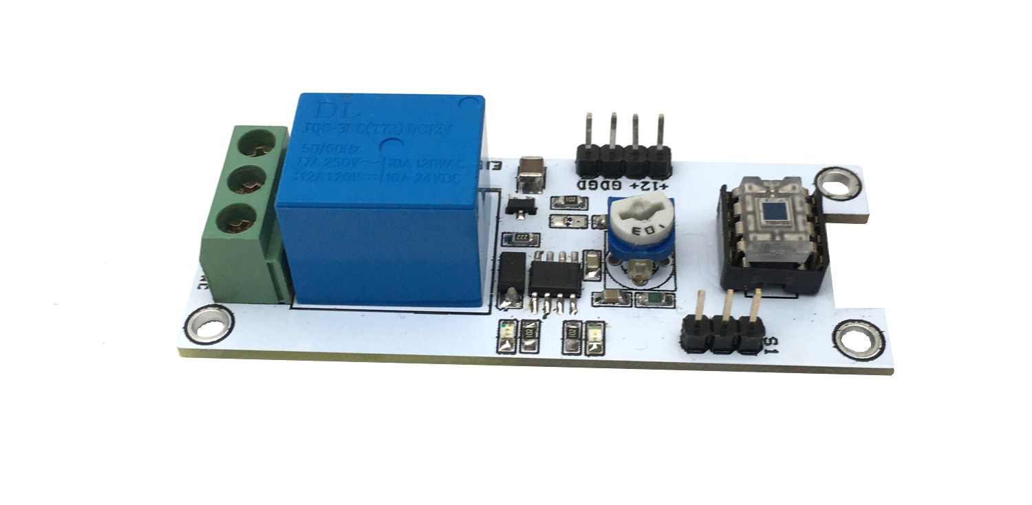
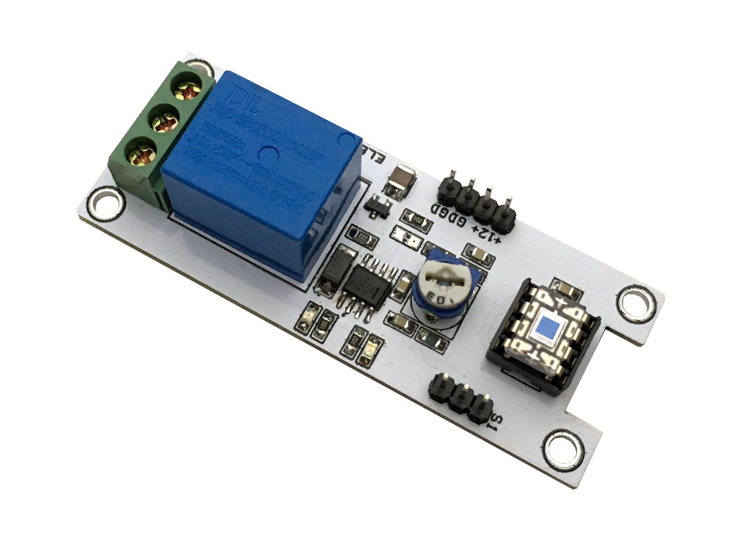
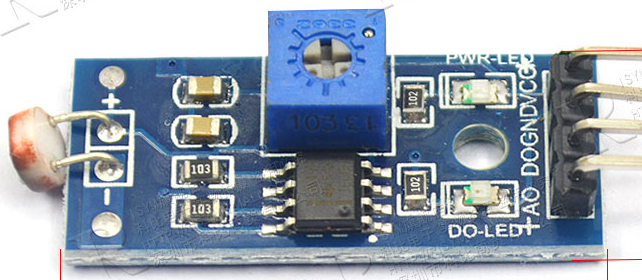
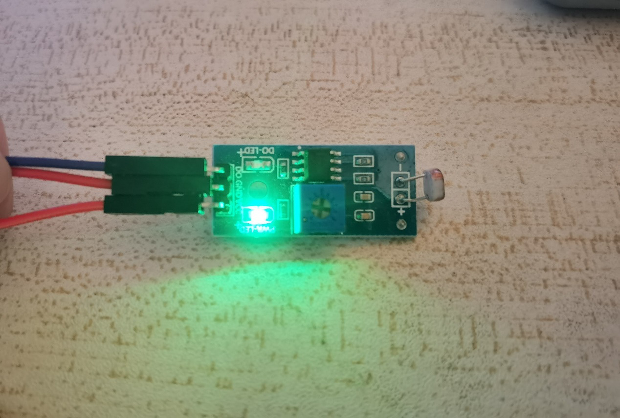
Photosensitive sensor
This time, the sensitive photosensitive resistance sensor is used, and the comparator output is used. The signal is clean, the waveform is good, and the driving capacity is more than 15mA. The same working voltage is 3.3V and 5V. There are analog signal output and digital signal output respectively. It is very convenient to develop. When the ambient light brightness can not reach the set threshold, the do terminal outputs high level, and when the ambient light brightness exceeds the set threshold value Do output low level.
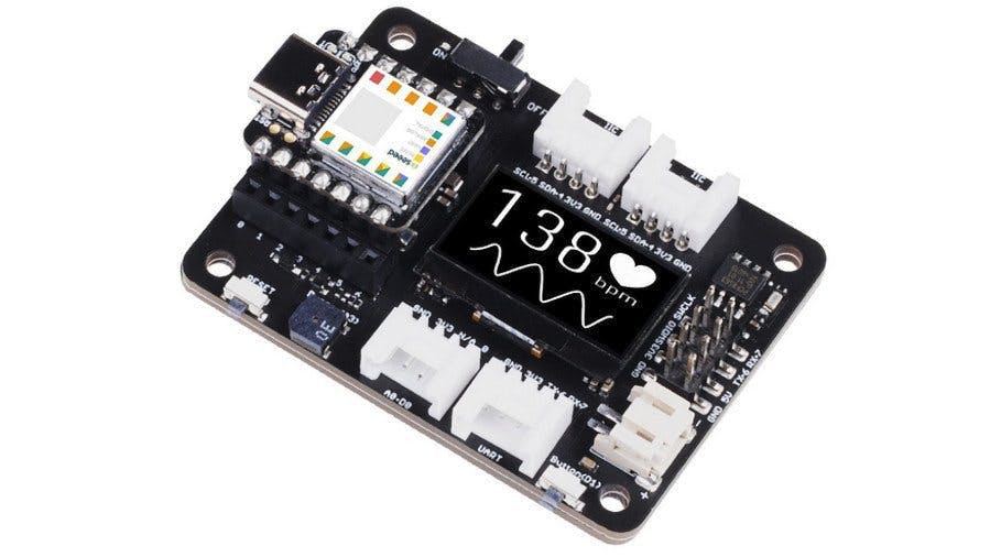
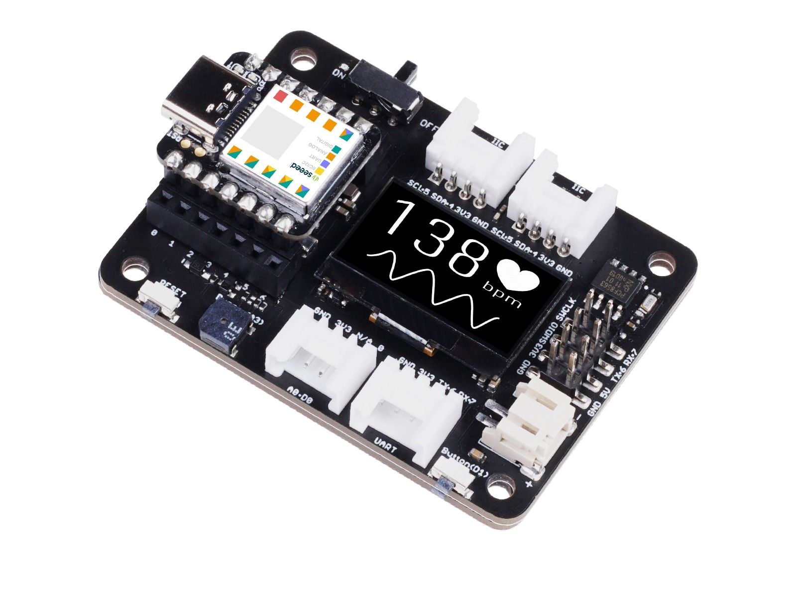
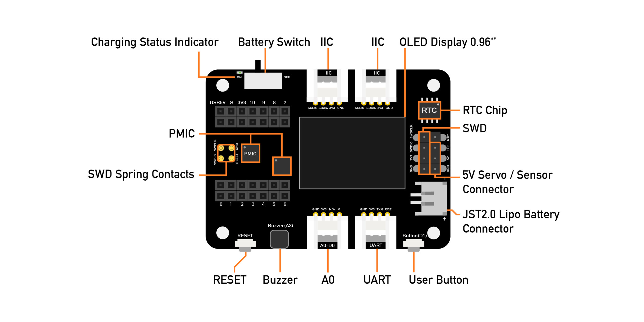
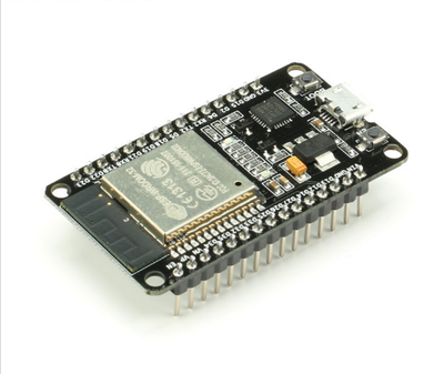
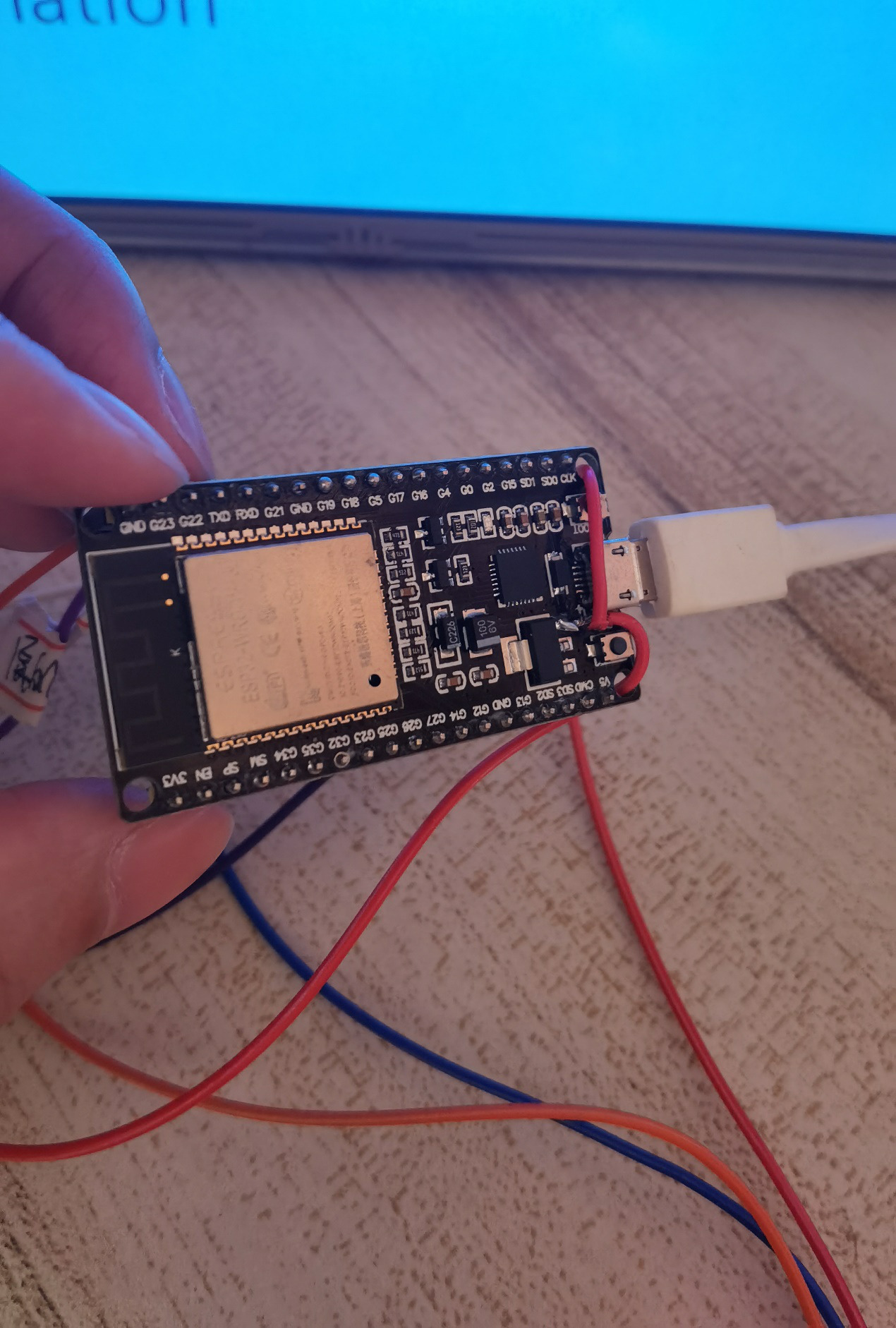
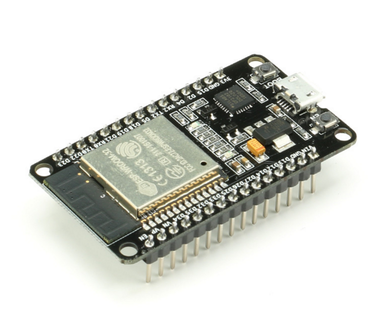
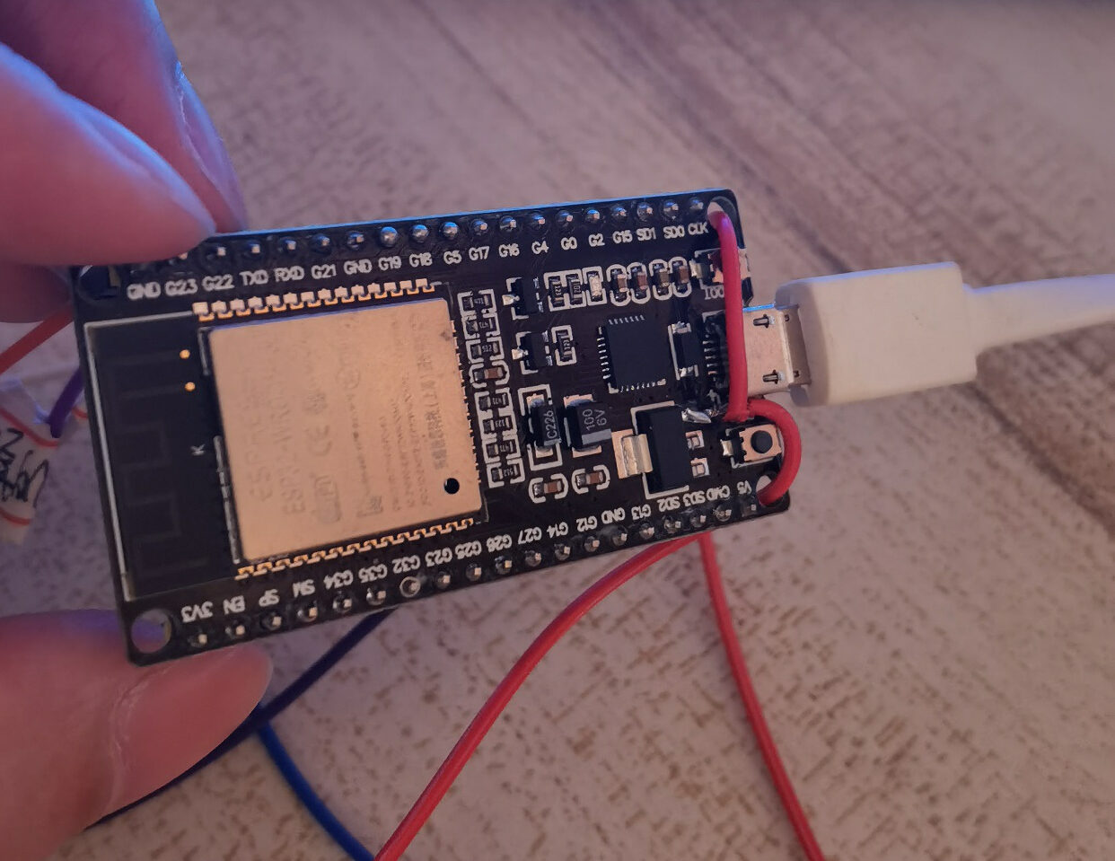
ESP32
Esp32 is a general-purpose wifi-bt-ble MCU module with powerful functions and wide applications. It can be used in low-power sensor networks and demanding tasks, such as voice coding, audio streaming and MP3 decoding. It also integrates a wealth of peripherals, including capacitive touch sensor, Hall sensor, low noise sensor amplifier, SD card interface, Ethernet interface, high-speed SDIO / SPI, UART, I2S and I2C. It can achieve the maximum range of wireless communication. It has the best performance in high integration, wireless transmission distance, power consumption and network connectivity.
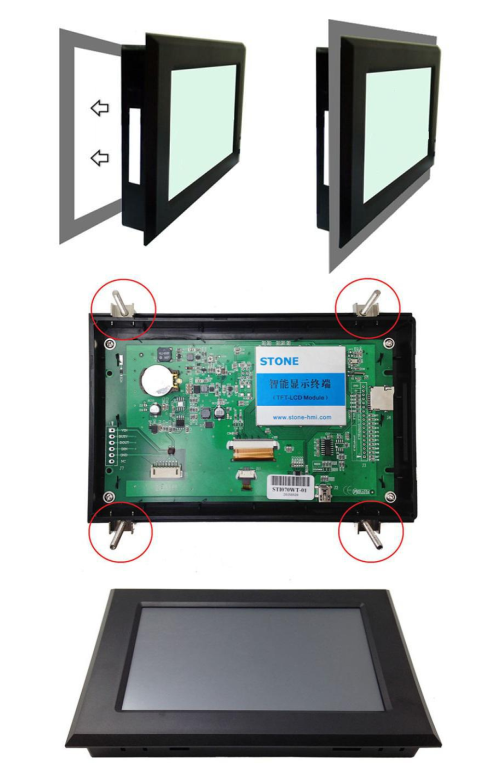
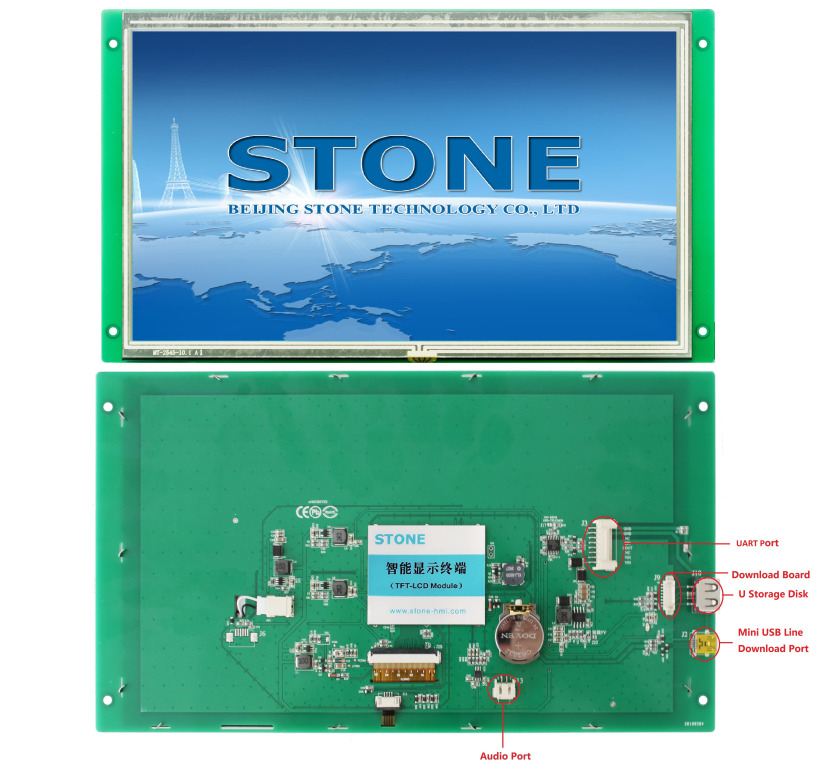
STVC101WT-01
- 10.1 inch 1024×600 industrial grade TFT panel and 4-wire resistance touch screen;
- brightness is 300cd / m2, LED backlight;
- RGB color is 65K;
- visual area is 222.7mm * 125.3mm;
- visual angle is 70 / 70 / 50 / 60;
- working life is 20000 hours. 32-bit cortex-m4 200Hz CPU;
- CPLD epm240 TFT-LCD controller;
- 128MB (or 1GB) flash memory;
- USB port (U disk) download;
- toolbox software for GUI design, simple and powerful hex instructions.
Basic functions
- Touch screen control / display image / display text / display curve / read and write data / play video and audio. It is suitable for various industries.
- UART interface is RS232 / RS485 / TTL;
- voltage is 6v-35v;
- power consumption is 3.0w;
- working temperature is – 20 ℃ / + 70 ℃;
- air humidity is 60 ℃ 90%.
STVC101WT-01 module communicates with MCU through serial port, which needs to be used in this project. We only need to add the designed UI picture through the upper computer through the menu bar options to buttons, text boxes, background pictures, and page logic, then generate the configuration file, and finally download it to the display screen to run.
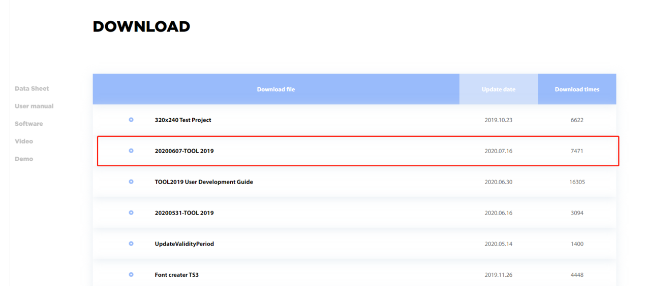
The manual can be downloaded through the official website: https://www.stoneitech.com/support/download
In addition to the data manual, there are user manuals, common development tools, drivers, some simple routine demos, video tutorials, and some for testing projects.
Design and production
ESP32
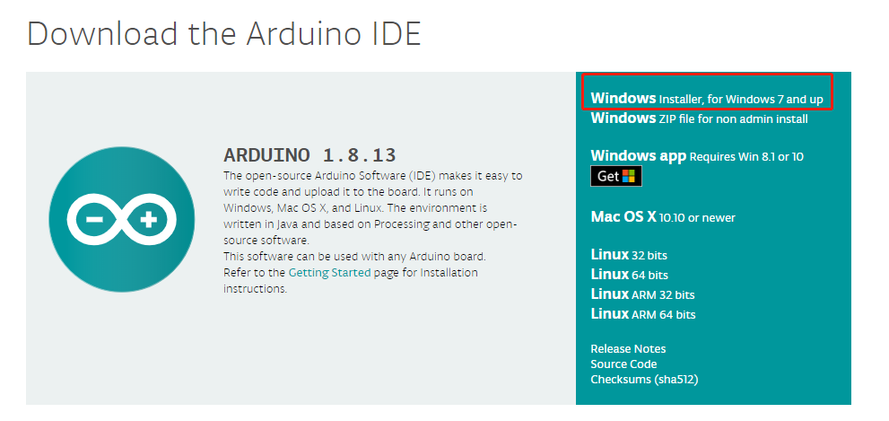
First of all, before developing esp32 code, you need to go to the official website to download and install the development environment, that is, Arduino IDE, and enter the Arduino official website: https://www.arduino.cc/en/Main/Software.
After the completion of the installation of new projects, and add the relevant code, the most important time to receive buf.
TOOL 2019
Download tools
To develop based on our STONE TFT LCD, we need to use a host computer development software tool 2019. On this host computer, all screen related settings are carried out on this host computer.
How to download it? Click the link below to enter the official website: https://www.stoneitech.com/support/download/software
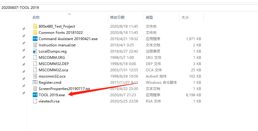
After the download, because the tool is not installed, it can be placed anywhere on the hard disk and can be run by double-clicking.
New project
Find the tool 2019.exe in the directory and double-click to open it.
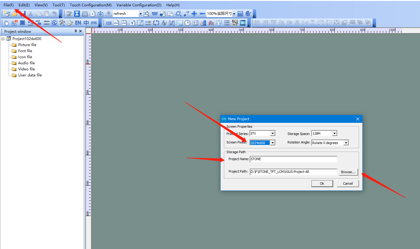
Select “New project”, set the screen size to 1024 * 600, and set the project name to STONE. Finally, select the path to save the project, and then click OK.
Add picture
After the previous step is completed, first delete the default blue background image, and then need to add the image needed by this application, these pictures are made in advance. The size of the background image should be consistent with the actual size of the screen, that is, 1024 * 600.
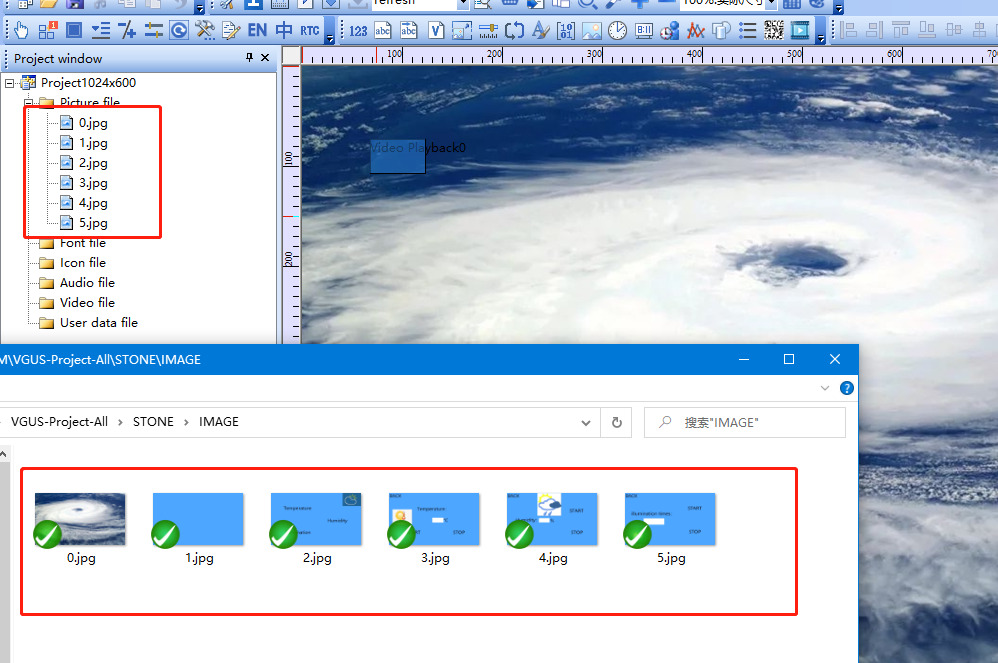
Find the picture file directory, right-click to select add, and select the desired picture in the pop-up window.
Interface
Page Jump settings
In the display, we will inevitably use the function of switching pages. Here, take the temperature interface as an example.
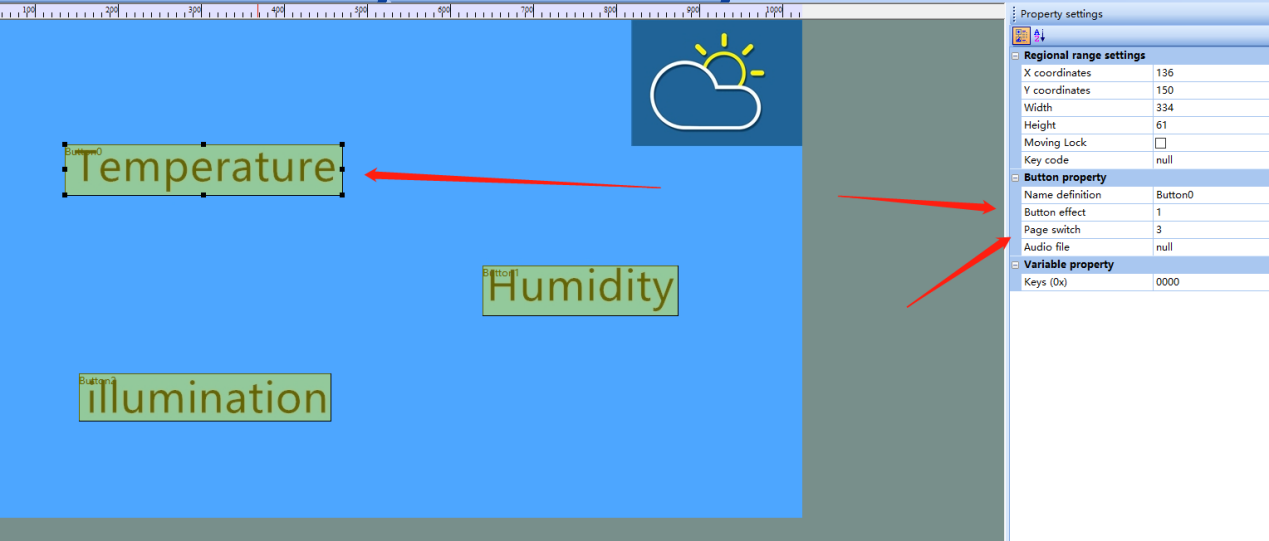
First, add a button control to the temperature, select the “button” control, and draw the corresponding area; then, in the feature setting on the right, set the button effect. Here, select Page 1, that is, when the button is pressed, the effect of page 1 will be displayed in the corresponding area; then, select the page switching function, and the page No. 3 selected here will immediately press this button Switch to page 3, which is the temperature display interface.
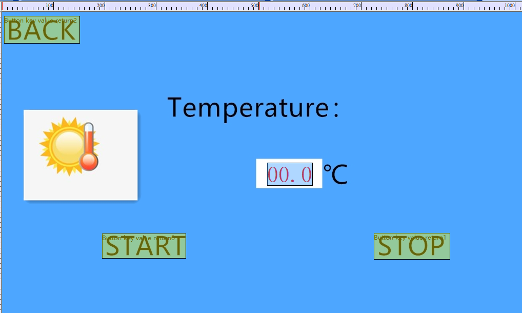
Text display settings
In the temperature display interface, a text display control is needed to display the real-time temperature data transferred from esp32. Therefore, it is necessary to add a data variable control, as shown in the figure below.
Then set the control.
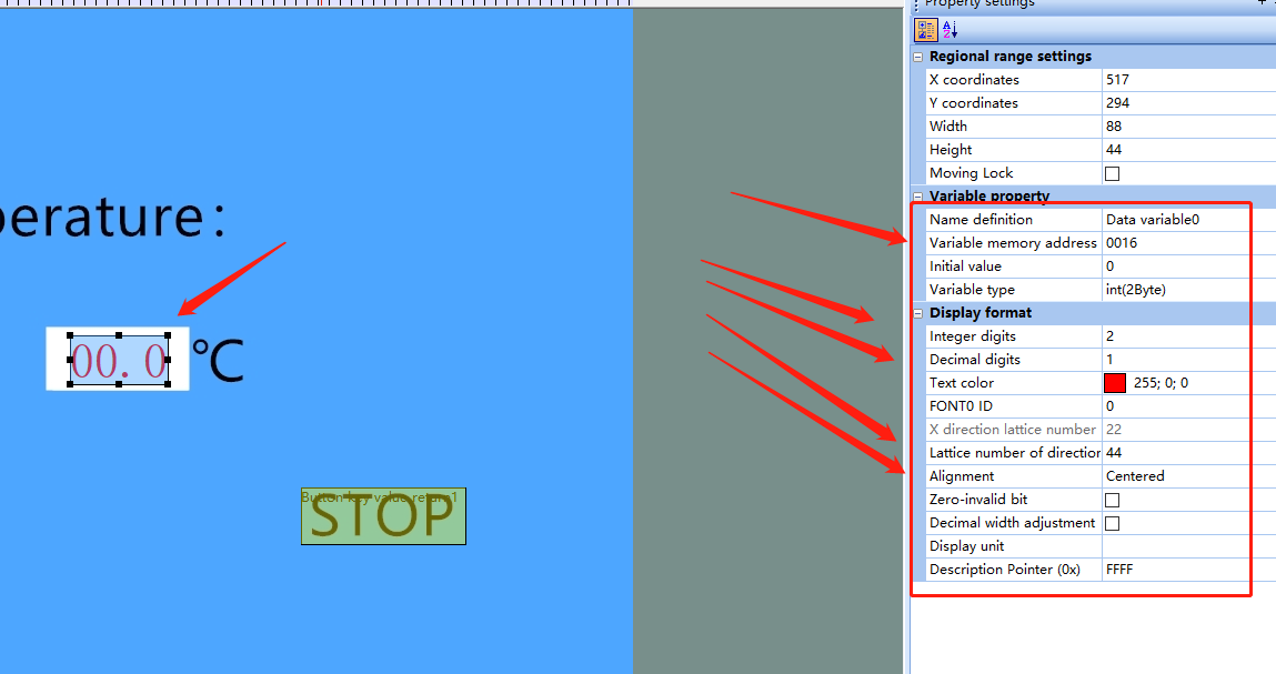
First of all, you need to set the variable address of the control. This address is very important. The data of MCU can only be displayed by sending data to this address. Then set the display format. Here, select 2-digit integer and 1-digit decimal. If you think the displayed font size is too small to see clearly, you can also adjust the font size. Finally, the alignment method is used. Generally, I choose the center alignment However, there are also left and right alignment options.
Key command control
Sometimes the STONE TFT LCD also needs to control the microcontroller to achieve a two-way interaction. This is also the case here. It is necessary to realize the functions of start acquisition and stop acquisition. Take stop button as an example.
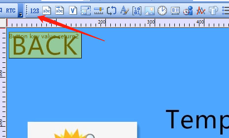
Select the “return pressed key value” control, which is different from “button”. It can send the key value to the MCU, so that the SCM can make corresponding response.
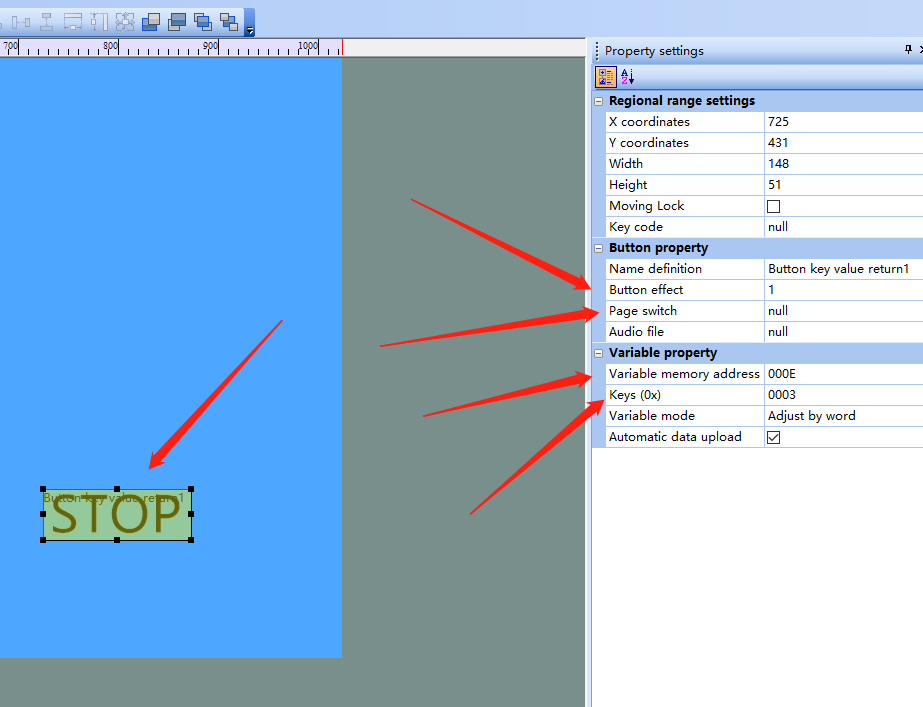
First of all, set the key effect. Select Page 1 here. When the key is pressed, the effect of page 1 will be displayed. There is no need to switch the page here, so select null. It should be noted that a variable address should also be set. This variable address cannot be repeated, otherwise it may be invalid. The variable address here is set to 0x000E, and a key value needs to be set to 0x0003, this value will also be issued as the key is pressed.
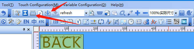
After setting, click compile, and then insert the U disk. After the identification is completed, click download to copy the project into the U disk, and plug in the display screen to upgrade. In this way, the whole project is completed.
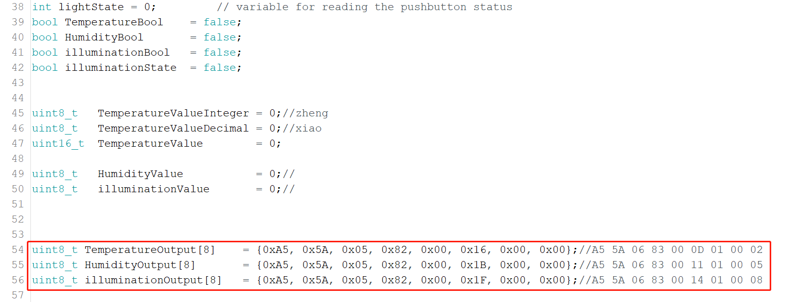
Code
if(Serial.available() != 0)

  {

    for(cout_i = 0; cout_i < 9; cout_i ++)

    {

        RecievedTemp[cout_i] = Serial.read();

    }

    switch(RecievedTemp[5])

    {

    case 0x0D://Temperature start

        TemperatureBool = true;

        break;

    case 0x0E://Temperature stop

        TemperatureBool = false;

        TemperatureOutput[6] = 0;

        TemperatureOutput[7] = 0;

        Serial.write(TemperatureOutput, 8);

        break;

    case 0x0F://Temperature back

        TemperatureBool = false;

        break;

    case 0x11://Humidity start

      HumidityBool = true;

        break;

    case 0x12://Humidity stop

        HumidityBool = false;

        HumidityValue = 0;

        HumidityOutput[7] = HumidityValue;

        Serial.write(HumidityOutput, 8);

        break;

    case 0x10://Humidity back

        HumidityBool = false;

        break;

    case 0x14://illumination start

      illuminationBool = true;

      illuminationState = false;

        break;

    case 0x15://illumination stop

      illuminationBool = false;

      illuminationValue = 0;

      illuminationOutput[7] = illuminationValue;

      Serial.write(illuminationOutput, 8);

        break;

    case 0x13://illumination back

      illuminationValue = 0;

      illuminationBool = false;

      break;

    default:

        break;

    }
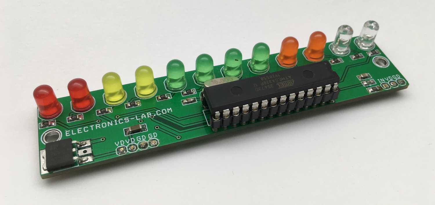
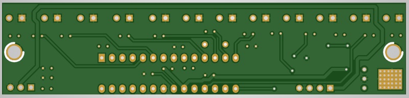
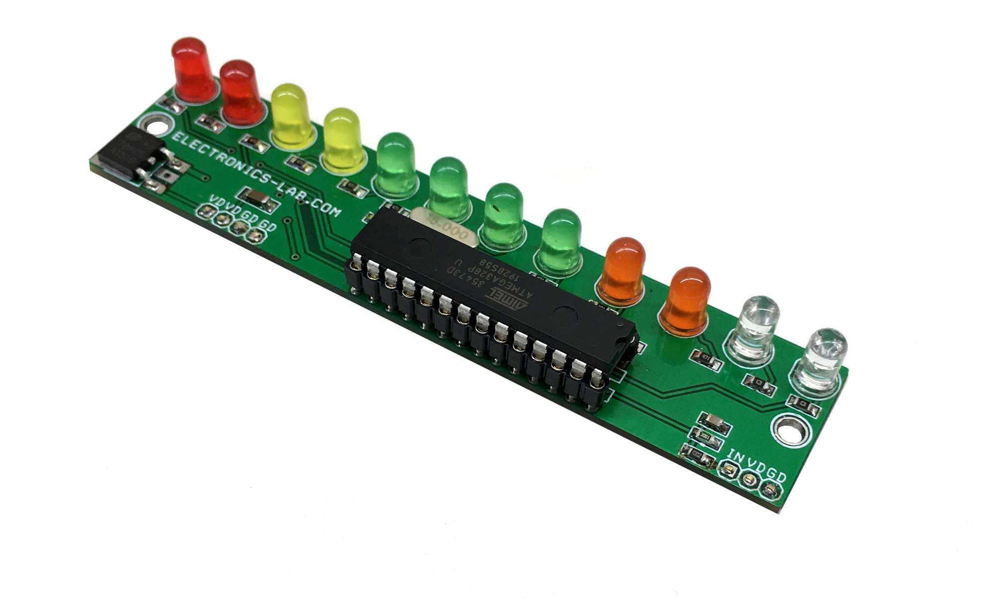
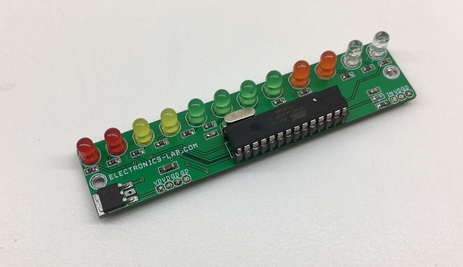
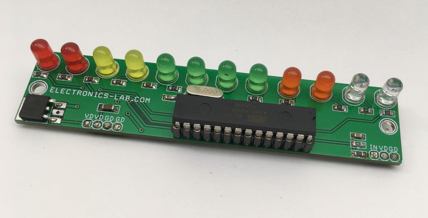
Photos