PWM Module with Dual Source/Sink Outputs using SG3525

SG3525 PWM module is a great tool for every hobbyist. This circuit can be used in various applications such as switching power supply, DC-DC converter, DC motor speed controller, LED dimer, High voltage power supply, solenoid driver, and electronic DC load.  This low-cost pulse width modulator control circuit offers improved performance. The circuit has various options such as adjustable PWM, adjustable frequency, optional soft start, dual source/sink output with 50% duty cycle, single output with 0 to 100% duty cycle and output signal voltage level TTL-5V or 12V selection using a jumper. The 5V PWM signal is rated at low current hence don’t draw more than 20mA. The 12V outputs are capable to drive a MOSFET directly.

PWM Module with Dual Source/Sink Outputs using SG3525 – [Link]

USRP B205mini-I Software-defined Radio Platform

A wide frequency range (70 MHz to 6 GHz) and a user-programmable transceiver

The USRP B205mini-i is a flexible and compact platform that is ideal for both hobbyist and OEM applications. It is designed by Ettus Research™ and provides a wide frequency range (70 MHz to 6 GHz) and a user-programmable, industrial-grade Xilinx Spartan-6 XC6SLX150 FPGA. USRPs are transceivers, meaning that they can both transmit and receive RF signals.

The RF front end uses the Analog Devices AD9364 RFIC transceiver with 56 MHz of instantaneous bandwidth. The board is bus-powered by a high-speed USB 3.0 connection for streaming data to the host computer. The USRP B205mini-i also includes connectors for GPIO, JTAG, and synchronization with a 10 MHz clock reference or PPS time reference input signal.

The hardware is conveniently accessible through the USRP Hardware Driver (UHD). UHD provides both a C/C++ and Python API and offers cross-platform support for multiple industry-standard development environments and frameworks, including RFNoC, GNU Radio, LabVIEW and Matlab/Simulink. And to ensure you have no restrictions on how you use UHD, it is available on Linux, Windows, and Mac OS. UHD provides the necessary control used to transport user waveform samples to and from USRP hardware as well as control various parameters (e.g. sampling rate, center frequency, gains, etc) of the radio.

RF Capabilities

  • 1 TX, 1 RX
  • 70 MHz to 6 GHz Frequency Range
  • Up to 56 MHz instantaneous bandwidth

Software

  • USRP Hardware Driver 3.9.2 (or later)
  • GNU Radio

Synchronization

  • 10 MHz clock reference
  • PPS time reference

Specifications

HOW CAN I GET STARTED?

There is also a 10-minute video demonstrating how to build an FM receiver with a USRP and GNU radio available here.

USRP B205 Mini is now available in Mouser.

UP Xtreme i11 Edge Compute Enabling Kit: Power the Edge with 11th Generation Intel® Core™

AAEON, a leading manufacturer of AI Edge hardware solutions, announces the latest addition to their UP Bridge the Gap brand, the UP Xtreme i11 Edge Compute Enabling Kit. Powered by the 11th Generation Intel® Core™ processors with Intel® Iris® Xe embedded graphics (formerly Tiger Lake), the UP Xtreme i11 is the latest generation in edge computing solutions designed to power intelligent applications across a range of industries including retail, healthcare, transportation, robotics and industrial automation.

Powered by the latest 11th Generation Intel Core processors, the UP Xtreme i11 Edge Compute Enabling Kit is designed to bring high performance computing to the edge. This latest generation of Intel Core processors bring speeds up to 4.4 GHz with a TDP of only 28 Watts and cTDP of 15 Watts. The processors also unlock a range of Intel tools designed to optimize performance and security, including the Intel® Functional Safety Essential Design Package, vPRO (i5, i7 only), TSN and TCC enabled LAN ports for real-time networking support.

The integration of Intel Iris Xe graphics into the 11th Generation Intel Core Processors brings the most powerful version of Intel’s integrated graphics to date. With up to 96 execution units (EUs), Intel Iris Xe enables workload consolidation in applications like CNC machines, HMI devices, medical imagining and diagnostics, and other applications requiring high resolution HDR output with AI capabilities.

The UP Xtreme i11 Edge Compute Enabling Kit is an innovative package featuring 5G support to deliver the ultimate modern edge solution. With 5G and wireless capabilities, the UP Xtreme i11 enables developers to connect large numbers of IoT devices, and seamlessly share data between edge and cloud. 5G wireless communication allows developers access to speeds up to 20 Gbps with reliable, ultra-low latency data transmission to provide a solid foundation for AI applications to evolve.

The UP Xtreme i11 Edge Compute Enabling Kit is built AI-Ready. Compatible with VPU cards including AAEON’s AI Core XM2280 with Intel® Movidius® Myraid™ X VPU, or the upcoming AI Core KB2280 featuring the 3rd Generation Intel® Movidius® VPU (formerly Keem Bay) which offers up to 10 times the performance for AI inferences than the Intel Movidius Myriad X, but up to 4.7 times more power efficiency. As with all AAEON UP products, the UP Xtreme i11 kit is compatible with the Intel® distribution of OpenVINO™ toolkit, as well as Intel® OneAPI, enabling access to optimization and training tools designed to accelerate development and shorten time-to-market.

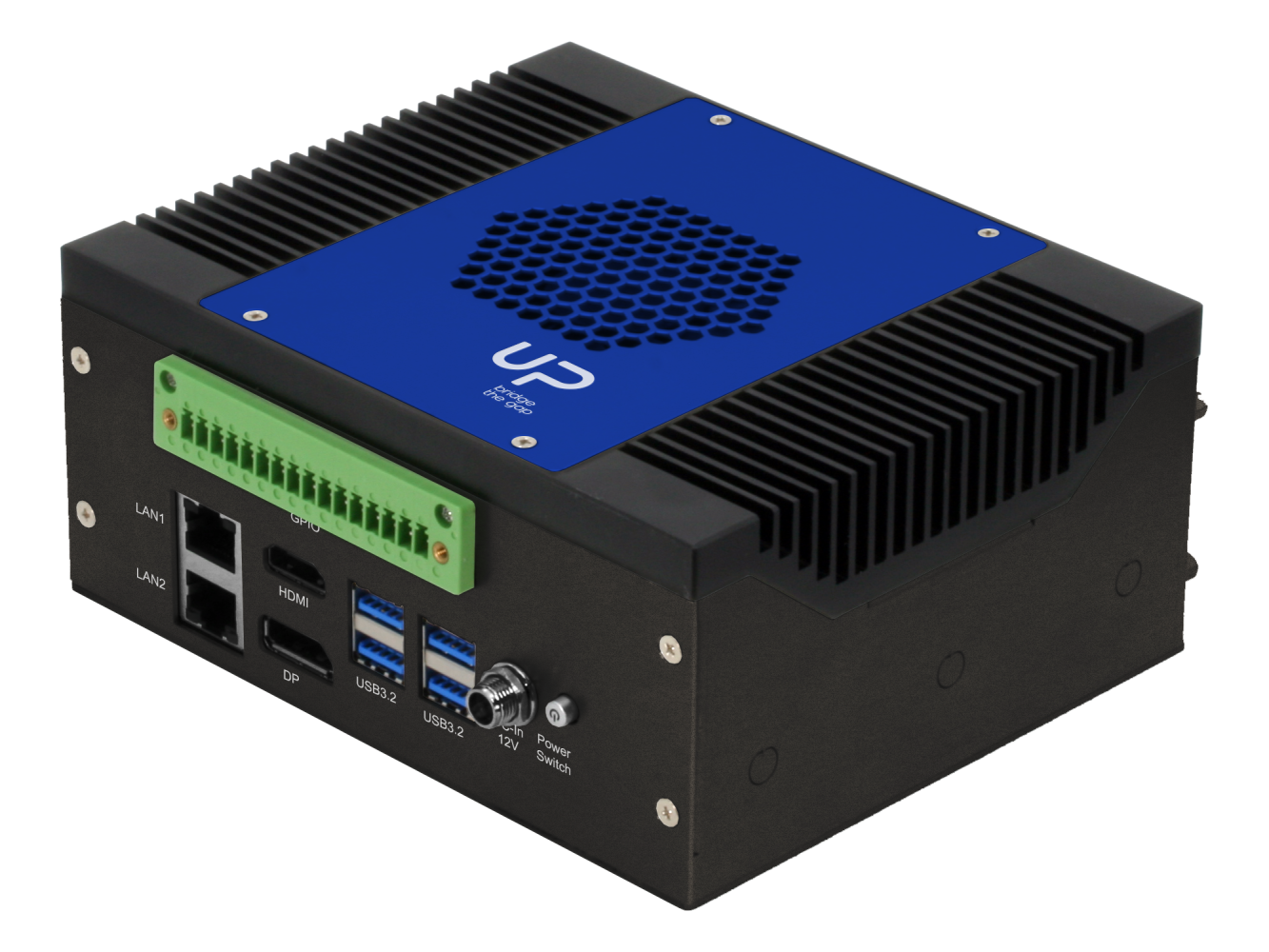
The UP Xtreme i11 combines powerful processing with a range of features designed to unlock the full potential of AI Edge computing. The kit features up to 64GB of memory with in-band ECC support to maximize processing speeds. Flexible I/O features include 1 Gbps and 2.5 Gbps LAN ports, four USB 3.2 Gen 2 (10 Gbps) ports and one USB 4 Type C port, and multiple display outputs including HDMI 2.0, DP and DP1.4 (via USB Type C) and eDP. The kit also features two RS-232/422/485 ports and audio line in/out.

The UP Xtreme i11 offers expandability features including M.2 2280 M-Key (with NVMe support), M.2 2230 E-key, M.2 3052 B-Key, and PCIe [x4] slots. The kit also features a 40-pin GP bus allowing greater flexibility in expansion and connecting with peripherals.

The UP Xtreme i11 Edge Compute Enabling Kit will be available for pre-order in the UP Shop starting in Q1 2021. More information about the kit can be found at UP-Board.org. AAEON also offers customization services for the UP Xtreme i11 to provide the best fit for any application. For more information about customization and OEM/ODM services, visit aaeon.com or contact an AAEON representative.

Liquid or Air Pressure Switch with Relay

This pressure switch project is built using a piezoresistive transducer, LM358 OPAMP as comparator, and a relay. The circuit activate the relay when the pressure in a system exceed a given set-point. Basically, this switch can power ON or OFF a pump, valve, motor, when certain pressure is reached. A trimmer potentiometer is provided to set the trigger point. LM358 is used as comparator, relay has Normally Open/Normally closed contacts with current rating 5Amps @ 230V AC or 10Amps @ 28V DC. LM78L05 IC is used to provide 5V DC supply to pressure sensor.  Operating voltage of this circuit is 12V and it consumes approx. 40mA current when Relay is in ON condition. We have used MPXV5010DP pressure sensor from NXP. This is an analog pressure sensor and the output of this sensor is 0.2V to 4.7V which is proportional to the applied pressure range of 0-10kPa (0 to 1.75PSI).

Possible application of this switch is, industrial pumps, small compressor, low pressure vacuum pump, medical equipment, appliance liquid level and pressure measurement.

One of the great uses of this switch, is to measure the liquid level in tank and trigger a PUMP or Valve at set point. Measuring the range of a liquid in tank is 0 to 100 cm and this corresponds to a pressure range of 0 to 10kPa. See the setup diagram below on ow to use the board as water level on/off switch.

The MPXV5010DP series piezoresistive transducers are state-of-the-art monolithic silicon pressure sensors designed for a wide range of applications, but particularly those employing a microcontroller or microprocessor with A/D inputs. This transducer combines advanced micromachining techniques, thin-film metallization, and bipolar processing to provide an accurate, high level analog output signal that is proportional to the applied pressure. The axial port has been modified to accommodate industrial grade tubing.

The MPXV5010DP sensor

Features

  • Operating Supply 12V DC
  • Maximum Current Consumption 40mA
  • Switch trigger relay when pressure 0 to 10kPa applied
  • Switch Can work with Air pressure or Liquid level
  • Relay Output is NO/NC
  • Relay Switch 5Amps 230V AC or 10Amps 28V DC
  • PCB dimensions: 66.68 x 26.67 mm

Schematic


Parts List

Connections

Gerber View

Test Setup

Photos

Video


MPXV5010DP Datasheet

PWM Module with Dual Source/Sink Outputs using SG3525

SG3525 PWM module is a great tool for every hobbyist. This circuit can be used in various applications such as switching power supply, DC-DC converter, DC motor speed controller, LED dimer, High voltage power supply, solenoid driver, and electronic DC load.  This low-cost pulse width modulator control circuit offers improved performance. The circuit has various options such as adjustable PWM, adjustable frequency, optional soft start, dual source/sink output with 50% duty cycle, single output with 0 to 100% duty cycle and output signal voltage level TTL-5V or 12V selection using a jumper. The 5V PWM signal is rated at low current hence don’t draw more than 20mA. The 12V outputs are capable to drive a MOSFET directly.

This module also has the feature of dual source/sink outputs. The output stages are totem-pole design capable of sinking and sourcing in excess of 200mA. The output stage of the SG3525A features NOR logic resulting in a low output for an off−state, both outputs are capable to drive the gate of a MOSFET. Open the jumpers J2 and J3 to set the module for source/sink mode. In this mode output frequency is 105Hz to 3.2Khz. Use R2 10 Ohms for source and sink mode.

Note: This IC is capable to work at frequency 100 Hz to 400Khz.  Output frequency span is dependent on capacitor C3 value, we have used 0.1uF capacitor which set the frequency 215Hz to 6.5Khz, by changing capacitor value to 0.01uF frequency range would change to 2.2Khz to 65Khz.

Features

  • Supply 12V DC (8-12V)
  • Frequency 215Hz to 6.5Khz (Single Output Mode)
  • Duty Cycle 0 to 100%
  • Frequency 105 Hz to 3.2Khz Dual output Source/Sink
  • Duty Cycle Dual mode 0 to 50%
  • Soft start Optional (Mount C2 10/16V Capacitor for Soft start)
  • On Board Power LED
  • PCB Dimensions 29.85X 15.88 mm

Single Output (0 to 100% Duty Cycle)

  • Close Jumper J2 and J3
  • Trimmer Potentiometer P1 Duty Cycle Adjust 0 to 100%
  • Trimmer Potentiometer PR1 Frequency Adjust 215Hz to 6.5Khz
  • Jumper J1 output voltage level selection 5V or 12V
  • If soft start required: Mount C2 10uF/16V for soft start or Omit for normal operation
  • CN1 Pin 4-PW and GND provides output

Dual Outputs  ( 0 to 50% Duty Cycle)

  • Open Jumper J2 and J3
  • Trimmer Potentiometer P1 Duty Cycle Adjust 0 to 50%
  • Trimmer Potentiometer PR1 Frequency Adjust 105Hz to 3.2Khz
  • Jumper J1 output voltage level selection 5V or 12V
  • If soft start required: Mount C2 10uF/16V for soft start or Omit for normal operation
  • CN1 Pin 3 OPB and Pin 5 OPA dual source Sink outputs

Schematic

Parts List

Connections

Gerber View

Photos

Video


SG3525  Datasheet

e-peas Releases AEM10941 Power Management IC for battery-less Monitoring Hardware

e-peas announced its AEM10941 power management IC (PMIC) has been designed into battery-less monitoring hardware from Xeelas.

The PMIC is optimized for photovoltaic-based energy harvesting deployments, covering 50mV to 5V input voltage range with power up of just 3µW input. Further, it delivers two voltage-regulated outputs of 1.2-1.8V and 1.8V-4.1V.

Xeelas’ Series S gateway, which includes the PMIC, was built for the acquisition of periodic data on the operational status of non-powered assets in remote locations. The gateways also have two solar panels which may be used as GPS antennas for accurate location fix.

Per the company, the cellular IoT plus GSM connectivity allow data transmission, as well as over-the-air updates.

For more information, visit https://xeelas.nl or www.e-peas.com

STMicroelectronics TSC213 current sense amplifiers

TSC213 is a zero-drift current sense amplifier that can sense current via a shunt resistor over a wide range of common-mode voltages from -0.3 to +26 V, whatever the supply voltage is

TSC213 is a zero-drift current sense amplifier that can sense current via a shunt resistor over a wide range of common-mode voltages from -0.3 to +26 V, whatever the supply voltage is. The TSC213 is designed with a specific zero-drift architecture, which can achieve high precision. TSC213 is a current sense amplifier that may be used in various functions such as precision current measurement, over current protection, current monitoring, feedback loops. It fully operates over the broad supply voltage range of 2.7 to 26 V and over the industrial temperature range -40 to 125 °C.

Key features

  • Wide common mode voltage: -0.3 to 26 V
  • 2.7 to 26 V supply voltage
  • Gain of 50 V/V
  • Offset voltage: ±100 µV max.

Additional features

  • Wide common-mode voltage: -0.3 to 26 V
  • Offset voltage: ±100 µV max.
  • 2.7 to 26 V supply voltage
  • Gain available (50 V/V)
  • Gain error: ±1% max.
  • Offset drift: 0.1 µV/°C max.
  • Gain drift: 20 ppm/°C max.
  • Quiescent current: 100 µA
  • QFN10 (1.8 x 1.4 mm) and SC70-6

more information: https://www.st.com/en/amplifiers-and-comparators/tsc213.html

LD49100 Low Quiescent Voltage Regulator

STMicroelectronics’ voltage regulators are stable with ceramic capacitors on the input and output

STMicroelectronics’ LD49100 provides 1 A maximum current with an input voltage range from 1.5 V to 5.5 V and a typical dropout voltage of 200 mV at 1 A output current. The device is stable with ceramic capacitors on the input and output.

The ultra low-dropout voltage, low quiescent current and low-noise features make it suitable for a wide range of automotive applications. Power supply rejection is 70 dB at low frequency and starts to roll off at 10 kHz. Enable logic control function puts the LD49100 in shutdown mode, allowing a total current consumption lower than 1 μA.

  • AEC-Q100 qualified
  • Temperature range: -40°C to +125°C
  • Input voltage from 1.5 V to 5.5 V
  • Ultra low-dropout voltage (200 mV typ. at 1 A load)
  • Very low quiescent current (20 µA typ. at no load)
  • Very low-noise with no bypass capacitor (30 µVRMS at VOUT = 0.8 V)
  • Output voltage tolerance: ±2.0%
  • DFN6 (3 mm x 3 mm) package with wettable flanks

more information: https://www.st.com/en/power-management/ld49100.html

Vecow SPC-7000/7100 – Compact and Fanless Tiger Lake UP3 Embedded Box PC for AI-related Applications

Barely a month after Vecow introduced the SPC-6000 fanless embedded PC powered by an Atom x6425RE Elkhart Lake processor, the company is back to announce another ultra-compact fanless embedded box PC aimed at delivering powerful computing performance and outstanding graphics to meet the demands of the fast-growing AI-related applications.

Vecow SPC-7000/7100 box PC is powered by the latest 11th Gen Intel® Core™ i7/i5/i3 processor (Tiger Lake UP3) that supports up to 32GB DDR4 3200HMz memory and between 12W and 28W TDP. It also features the Intel® Iris® Xe Graphics that supports dual simultaneous and independent displays up to 8K resolution, alongside a 9V to 55V DC-in power input, optional full function SUMIT A, B expansion, one 2.5GbE LAN and TSN networking, which make it perfect for factory automation, service robot, cellular V2X, smart retail, Industry 4.0 and AIoT applications.

The SPC-7000 is exactly the same as the SPC-7100 but the company added fins to the metal top cover of the SPC-7100 for extra cooling; the reason for the difference in dimensions, weight and temperature range.

Features and Specifications of the Vecow SPC-7000/7100 include:

  • 11th Gen Intel® Core i7/i5/i3 quad-core (Tiger Lake UP3) processor with 12W to 28W configurable TDP
  • Intel UHD graphics or Intel Iris Xe Graphics for discrete-level graphics performance, supports DirectX 12, OpenGL 4.6, OpenCL 2.0, and max 8K resolution
  • Up to 32GB 3200MHz DDR4 SO-DIMM memory
  • 1x M.2 Key B 2260 Socket
  • 1x SATA III (6Gbps)
  • SPI flash for AMI BIOS
  • 1x GbE via Intel Ethernet Controller I219LM with support for iAMT (Intel Active Management Technology), Wake on LAN, PXE
  • 1x 2.5 GbE via Intel Ethernet Network Connection GPY215
  • WiFi 5/6 or/and 4G/5G cellular with Nano SIM card slot
  • Dual DisplayPort outputs up to 4096 x 2304 @ 60Hz
  • 2x USB 3.1 Type-A ports (10Gbps)
  • 2x USB 2.0 Type-A ports
  • 2x USB 2.0 via internal header
  • 2x COM RS-232/422/485
  • 1x M.2 Key B 3042/3052 Socket
  • 1x M.2 Key E 2230 Socket
  • 2x Stackable Unified Module Interconnect Technology A/B slots with customized chassis (optional)
  • Infineon SLB9670 TPM 2.0, SPI Interface
  • 3.5mm Mic-in jack, 3.5mm Line-out jack
  • Realtek ALC892 audio codec, 5.1 Channel HD Audio
  • Optional DIN Rail and VESA mounts.
  • Power, HDD, WWAN and WLAN LEDs
  • ITE IT8786E Embedded Controller
  • 16 mode ignition control
  • 2-pin remote switch
  • Watchdog timer, and,
  • 9V to 55V wide range DC Power input, via 3-pin terminal block with V+, V-, and GND
  • Operating System: Windows 10 or Linux
  • Dimensions:
    • Vecow SPC-7000 – 150.4 mm x 106.2mm x 48.1mm
    • Vecow SPC-7100 – 150.4 mm x 106.2x 62.1mm
  • Weight:
    • Vecow SPC-7100 – 0.9 kg
    • Vecow SPC-7100 – 1.3 kg
  • Temperature Range:
    • Vecow SPC-7000 – -40°C to 70°C (operating); -40°C to 85°C (storage)
    • Vecow SPC-7100 – -40°C to 85°C  (operating and storage)
  • Humidity: 5% – 95%
  • EMC: CE, FCC EN50155, EN50121-3-2

The company has not said anything on price or availability of the hardware yet, but you can visit the product page if you’d like to make further inquiry about the rugged computers.

Oscilloscope Tester Keyring (OTK) can test your oscilloscope

The Engineering Octopus has launched a keyring which helps you keep track of your keys, and also serves as a means to quickly test an oscilloscope. It is called the Oscilloscope Tester Keyring (OTK). About the inspiration for the project, Max the brain behind the OTK says

“All electronic engineers love to show off the fact that they’re electronic engineers, and what better way to do that than with a keyring! Not only will the bare electronics be noticed by many, it’s also a functional tester!” He continues “I made it because I wanted a tool I could take with me, to easily test oscilloscopes when I go and view them. Often, they don’t have the probes or any means of testing. Plus, I really wanted a cool electronic key ring, and I couldn’t find one!”

The OTK works by generating a pure sine wave (via a Colpitts resonant oscillator) at a particular frequency (current models generate either approx. 10MHz, 20MHz, 50MHz) which is ideally close to the bandwidth of the scope. It features a DC offset, which enables you to test almost all functions of the ‘scope, and carry it with you everywhere you go! It’s battery powered (not included) via a 2032 / watch battery. It also features a micro USB port so that you can use the oscilloscopes (or power banks) USB port for power.

About the scope, he says “

But my ‘scope has a square wave function, I hear you cry? Indeed, this is true, but firstly it doesn’t fit on a key ring / look cool, and secondly, you need probes to test it! Where the OTK really shines, is for those of you who love to repair / buy ‘scopes. More often than not, they’re not supplied with probes, and this is a quick and easy tool that can be taken with you to viewings. You simply plug it into the BNC connector, and test it out!”

Application of the OTK includes:

  • DC / AC / GND switch test
  • CRT Intensity
  • Horizontal / vertical positioning
  • Time base issues
  • Volts per division issues
  • Single Shot
  • Triggering issues

You can also apply it to a host of other things if you’re creative. However, we should note that the Oscilloscope Tester Keyring©, also referred to as OTK, is not designed as a substitute for reference testing, and is designed as a quick initial check of an oscilloscope, or similar equipment. The sine wave generated is approximately at the stated frequency of 10MHz.

It is not advised to keep the battery installed whilst the OTK is worn on a keyring, with keys. This is due to the potential shorting of the battery due to metallic keys. However, if this does occur, it is unlikely to cause any issues. “The products have been cleaned with IPA and Flux-OFF, while every effort has been made to ensure no residue of either remains, it may be possible that some is left. Please ensure suitable handling.” The OTK is  available from The Engineering Octopus priced at £8.50 or via Tindie for $10.99.

TOP PCB Companies